Page is loading ...

22 General Information
Couplings for
Grooved and
Plain-End
Ductile Iron Pipe
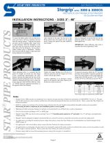
Installation
Instructions
Style 31 Coupling Style 307 Transition Coupling
Style 397 and 399 V-Grip Couplings

Couplings for Grooved and Plain-End Ductile Iron Pipe 23
Style 31
Coupling 3 – 12 inch (80 – 300 mm) Sizes
1. CHECK PIPE ENDS: The out-
side surface of the pipe, between the
groove and the pipe end, must be
smooth and free from deep pits and
swells to provide a leak-tight seal for
the gasket. All rust, loose scale, oil,
grease, dirt, and cutting particles
must be removed. Peened surfaces
may require rework to provide a leak-
tight seal for the gasket (refer to ANSI/
AWWA C-606 or CSA B242).
2. CHECK GASKET AND LUBRI-
CATE: Check the gasket to make
sure it is suitable for the intended ser-
vice. Apply a thin coat of Victaulic
Lubricant or silicone lubricant to the
gasket lips and exterior.
3. INSTALL GASKET: Install the
gasket over the pipe end. Make sure
the gasket does not overhang the
pipe end.
WARNING
• Read and understand all instructions before attempting to install any Victaulic piping
products.
• Depressurize and drain the piping system before attempting to install, remove, or adjust any
Victaulic piping products.
• Wear safety glasses, hardhat, and foot protection.
Failure to follow these instructions could result in serious personal injury, improper product
installation, and/or property damage.
CAUTION
• Always use a compatible lubricant to
prevent the gasket from pinching/tearing
during installation.
Failure to follow this instruction could result
in joint leakage.

24 Couplings for Grooved and Plain-End Ductile Iron Pipe
4. JOIN PIPE ENDS: Align and
bring the two pipe ends together.
Slide the gasket into position, and
make sure it is centered between the
grooves. Make sure no portion of the
gasket extends into the groove on
either pipe.
5. INSTALL HOUSINGS: Install
the housings over the gasket. Make
sure the housings’ keys engage the
grooves properly on both pipes.
6. INSTALL BOLTS AND NUTS:
Insert the bolts, and thread the nuts
finger-tight onto the bolts. Make sure
the oval neck of the bolts seat prop-
erly in the bolt holes.
7. TIGHTEN NUTS: Tighten all
nuts evenly by alternating sides until
metal-to-metal contact occurs at the
flat bolt pads. NOTE: It is important to
tighten all nuts evenly to prevent gas-
ket pinching.
CAUTION
• Make sure the gasket does not become
rolled or pinched while installing the
housings.
Failure to follow this instruction could cause
damage to the gasket, resulting in joint
leakage.

Couplings for Grooved and Plain-End Ductile Iron Pipe 25
* Standard, rigid radius-cut grooves provide no deflection or movement.
Allowable Pipe-End Separation and Joint
Deflection for Style 31 Couplings Flexible,
Radius-Cut Grooved, Cast (Gray/Ductile) Iron Pipe
Pipe Size
Allowable
Pipe-End
Separation *
inches (mm)
Deflection From Centerline
Nominal
Diameter inches
(mm)
Degrees Per
Coupling *
inches/one foot of
Pipe (mm/one
meter of Pipe) *
3 0 – 0.094
1° - 21’
0.280
80 0 – 2,4 7,1
4 0 – 0.094
1° - 8’
0.210
100 0 – 2,4 5,3
6 0 – 0.094
0° - 47’
0.140
150 0 – 2,4 3,6
8 0 – 0.094
0° - 36’
0.110
200 0 – 2,4 2,8
10 0 – 0.156
0° - 48’
0.150
250 0 – 4,0 3,8
12 0 – 0.156
0° - 41’
0.130
300 0 – 4,0 3,3
Style 31 Helpful Information
Pipe Size
Socket Size
inches
Nominal Diameter
inches (mm)
3
7
/
8
(80)
4
1
1
/
16
(100)
6
1
1
/
16
(150)
8
1
1
/
4
(200)
10
1
1
/
4
(250)
12
1
7
/
16
(300)

26 Couplings for Grooved and Plain-End Ductile Iron Pipe
Style 31
Coupling 14 – 36 inch (350 – 900 mm) Sizes
Style 31 Couplings,
in sizes 14 – 36 inches (388,6 – 972,8 mm), are cast in
segments to ease handling and ensure coupling concentricity.
1. CHECK PIPE ENDS: The out-
side surface of the pipe, between the
groove and the pipe end, must be
smooth and free from deep pits and
swells to provide a leak-tight seal for
the gasket. All rust, loose scale, oil,
grease, dirt, and cutting particles
must be removed. Peened surfaces
may require rework to provide a leak-
tight seal for the gasket (refer to ANSI/
AWWA C-606 or CSA B242).
WARNING
• Read and understand all instructions before attempting to install any Victaulic piping
products.
• Depressurize and drain the piping system before attempting to install, remove, or adjust any
Victaulic piping products.
• Wear safety glasses, hardhat, and foot protection.
Failure to follow these instructions could result in serious personal injury, improper product
installation, and/or property damage.
14 – 20 inch (388,6 – 548,6 mm) Sizes 24 – 36 inch (655,3 – 972,8 mm) Sizes;

Couplings for Grooved and Plain-End Ductile Iron Pipe 27
2. ASSEMBLE SEGMENTS:
Assemble the segments loosely into
two equal halves, as shown above.
Make sure the tongue and recess fea-
tures mate properly (tongue-to-
recess). Allow slight clearance
between the segments to ease
assembly onto the pipe.
3. CHECK GASKET AND LUBRI-
CATE: Check the gasket to make
sure it is suitable for the intended ser-
vice. Apply a thin coat of Victaulic
Lubricant or silicone lubricant to the
gasket lips and exterior.
4. INSTALL GASKET: For larger-
size couplings, it may be easier to
turn the gasket inside out, then slide it
over the pipe end. Make sure the gas-
ket does not overhang the pipe end.
5. JOIN PIPE ENDS: Align and
bring the two pipe ends together. If
the gasket was turned inside out in
step 4, roll the gasket into position,
and make sure it is centered between
the grooves. Make sure no portion of
the gasket extends into the groove on
either pipe.
CAUTION
• Always use a compatible lubricant to
prevent the gasket from pinching/tearing
during installation.
Failure to follow this instruction could result
in joint leakage.
Tongue
Recess
Exaggerated for clarity
CAUTION
• Make sure the gasket does not become
rolled or pinched while installing the
housings.
Failure to follow this instruction could cause
damage to the gasket, resulting in joint
leakage.
Pipe End
Exaggerated for clarity

28 Couplings for Grooved and Plain-End Ductile Iron Pipe
6. INSTALL FIRST SEGMENT
ASSEMBLY: Install one of the pre-
assembled halves over the gasket.
Make sure the housings’ keys engage
the grooves properly on both pipes.
6a. INSTALL REMAINING SEG-
MENT ASSEMBLY: Install the sec-
ond segment assembly over the
gasket, making sure the tongue and
recess features mate properly
(tongue-to-recess). Make sure the
housings’ keys engage the grooves
properly on both pipes. While sup-
porting the weight of the assemblies,
insert the remaining bolts, and thread
the nuts finger-tight onto the bolts.
NOTE: Make sure the oval neck of all
bolts seat properly in the bolt holes.
7. TIGHTEN NUTS: Tighten all
nuts evenly by alternating sides until
metal-to-metal contact occurs at the
bolt pads. Make sure the housings’
keys completely engage the grooves.
NOTE: It is important to tighten all
nuts evenly to prevent gasket pinch-
ing.
* Standard, rigid radius-cut grooves provide no deflection or movement.
Tongue
Recess
Exaggerated for clarity
Allowable Pipe-End Separation and Joint Deflection
for Style 31 Couplings;
Flexible, Radius-Cut Grooved, Cast (Gray/Ductile) Iron Pipe
Pipe Size
Allowable Pipe-End
Separation*
inches (mm)
Deflection From Centerline
Nominal Diameter
inches (mm)
Degrees Per
Coupling*
inches/one foot of
Pipe (mm/one meter
of Pipe) *
14 0 – 0.156
0° - 35’
0.110
350 0 – 4,0 2,8
16 0 – 0.250
0° - 49’
0.160
400 0 – 6,4 4,1
18 0 – 0.250
0° - 44’
0.140
450 0 – 6,4 3,6
20 0 – 0.250
0° - 40’
0.120
500 0 – 6,4 3,0
24 0 – 0.250
0° - 33’
0.110
600 0 – 6,4 2,8
30 0 – 0.469
0° - 51’
0.170
750 0 – 11,9 4,3
36 0 – 0.469
0° - 47’
0.150
900 0 – 11,9 3,8

Couplings for Grooved and Plain-End Ductile Iron Pipe 29
Style 31 Helpful Information
Pipe Size
Socket Size
inches
Nominal Diameter
inches (mm)
14
1
5
/
8
(350)
16
1
5
/
8
(400)
18
1
5
/
8
(450)
20
1
13
/
16
(500)
24
1
13
/
16
(600)
30
1
13
/
16
(750)
36
1
13
/
16
(900)
/