Page is loading ...

RP/IS-A-SSRiser
SS Riser
Installation, Maintenance, & Repair
Series IBR/IBR2 SS Risers
In-Building Riser
Sizes: 2" – 10"
WARNING
!
Read this Manual BEFORE using this equipment.
Failure to read and follow all safety and use information can
result in death, serious personal injury, property damage, or
damage to the equipment.
Keep this Manual for future reference.
You are required to consult the local building and plumbing
codes prior to installation. If the information in this manual
is not consistent with local building or plumbing codes,
the local codes should be followed. Inquire with governing
authorities for additional local requirements.
WARNING
!

Ames Fire & Waterworks In-Building Risers are designed for
easy installation in standard configurations as outlined using
standard construction method.
The floor penetration detail of the In-Building Riser shall be
restrained per direction outlined by site plans. Consult Uni-Bell
handbook of PVC pipe if instructions are not provided.
Instructions for standard AWWA C900 gasket coupler
(either ductile iron or PVC), available in sizes 4"-10".
Installation in accordance with the following information
(from Uni-Bell handbook)
1. Clean out inside of coupler making certain the beveled
spigot end and the gasket groove are free of dirt.
2. Apply lubricant to beveled spigot (male).
3. Insert gasket into coupling groove and seat firmly.
4. Push lubricated end past gasket into the bell housing. (Ames
in-building risers are equipped with the lugs placed 180°
apart on either side of the unit which can be used to “pull”
the pipe into the bell using a “come a-long” type equipment.
Also, the “bar and block method described in the Uni-Bell
handbook can also be used for installation).
5. The maximum allowable pipe deflection angle between the
IBR and underground pipe is as follows:
Instructions for the AWWA specification C606 grooved
connections. All underwriters Laboratory approved groove
couplers made to fit the AWWA C606 grooves can be used
to join the connection to the in-building supply line.
1. Check gasket and lubricate it using groove coupler manu-
facturer's recommended lubricant or approved equal.
2. Install gasket. Place gasket over pipe end being sure gasket
lip does not overhang pipe end.
3. Align and bring two pipe ends together and slide gasket into
position centered between grooves or each pipe (no portion
of the gasket should extend into the groove of either pipe.)
4. Apply housings. Place housings over gasket, being sure the
housing keys engage into the grooves of the pipe. (No por-
tion of the gasket should extend into the groove of either
pipe.)
5. If restraint fitting is being used tighten nuts: Tighten nuts
alternately and equally until housing bolt pads are firmly
together metal to metal: Uneven tightening will cause gasket
to pinch.
2
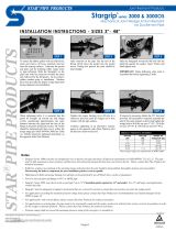
Basic Installation Instructions
Outlet
Flow
Building Perimeter
Building
Floor
Inlet
Flow
TR Size Maximum Deflection
4" 1°
6" 1°
8" 1°
10" 1°
Instructions for NPT connections, either to connect to the
underground supply or the in-building supply line. Also
used to install the FNPTxFNPT or FNPTxFlange adaptor.
1. Inspect all threads for damage/burrs. Any damaged sealing
surfaces may result in a difficult or failed installation.
2. Apply NSF61 Approved/Compliant thread sealant paste or
tape to male fitting according to the sealant manufacturer’s
directions. Ensure that the thread sealant is compatible with
all materials it may come in contact with.
3. Tighten fittings hand tight as far as possible. Then, using a
wrench or other appropriate tool that will not damage the fit-
tings or pipe, tighten an additional 1.5-2.5 turns until snug.
DO NOT OVERTIGHTEN – overtightening may result in dam-
age to the female connector and possible failure of the joint.
Instructions for installation using the FNPTxFlange adaptor.
1. Install the FNPTxFlange adaptor to the appropriate MNPT
end of the riser using above instructions for NPT connec-
tions.
2. Inspect all components to make sure they are free of debris,
damage, or defects. This includes flange faces, bolts, nuts,
washers, and gasket.
3. Lubricate bolt threads, nut threads, and washer surfaces
where they will contact the bolt head or nut.
4. Ensuring that both flanges are aligned, install gasket, bolts
and washers. Hand tighten nuts.
5. Using an appropriate cross-pattern tightening procedure,
tighten bolts.
6. Inspect joint, making sure that the gap between flange faces
is even around their circumference.
CAUTION
!
Do not reuse old gaskets

3
Installation
Materials
Because the In-Building Riser is buried, the material of con-
struction has been chosen as Type 304L Stainless Steel. This
material is generally recognized as a corrosion resistant material
which is superior to Cast, Ductile Iron, or Coated Steel pipe for
corrosion resistance, and which is superior to engineered plas-
tics for strength and longevity. In general, the stainless steel is
the cathode in joints of dissimilar metal, so that any corrosion
which may occur will not affect the stainless steel. In addition,
an extra protection is provided in that there is no actual metal to
metal contact at either joint when using the CIPS bell connection
or groove coupler designs.
Installation Practices
Good installation practice for all types of buried pipe often calls
for wrapping of the pipe to decrease corrosion due to soil con-
ductivity. Although stainless steel is less susceptible to corro-
sion. Inquire with local governing authorities for local installation
requirements.
Field Test Procedures
Normal field test procedures call for a hydrostatic pressure test
of the system prior to final acceptance. Often, segments of the
system will be tested individually prior to the complete system
test. Two methods are recommended to hydrostatically test the
In-Building Riser based upon the following conditions.
1. Constrained Piping
If the piping installation is essentially complete, the piping
restraints may adequately take the thrust loads generated by
having a blind end on the pipe system. In these cases, no spe-
cial actions to restrain thrust or side loads are required, and the
fitting installed in the system may be adequate for hydrostatic
testing.
2. Free Piping
If just the riser or riser/main connection is to be tested, then the
thrust loads from the blind end cap on the riser may need to be
restrained. The riser design has been tested in the unrestrained
state using a rigid coupler and end cap grooved fitting. Flange
adapters, expansion fittings, or other styles of end connectors
may result in excessive end thrust which may cause a leak or
fitting malfunction. In addition, couplings which are adequately
rated for high pressure testing should be used if thrust restraints
are not feasible.
NOTICE
It is important that all air is bled from the system before pressurizing any
component.
End Connections
Bell End: Mates with Ductile Iron Pipe and AWWA C900 Pipe
(PVC Pipe with Cast Iron Pipe Equivalent OD's). Available in
sizes 4" to 10"
SIZE SEALING GASKET (CIPS – C900)
in. mm Mating Pipe OD Spare Part Ordering code
4 100 4.80 7014421
6 150 6.90 7014422
8 200 9.05 7014423
10 250 11.10 7014424
MNPT End: Optional adapters to convert the MNPT end(s) of a
riser to FNPT or a flanged connection. Available in sizes 2"-3".
SIZE ADAPTER
in. mm Type Spare Part Ordering code
2 50 Flange Adapter 88008100
2 50 FNPT Adapter 88008103
2
1
⁄2 65 Flange Adapter 88008101
2
1
⁄2 65 FNPT Adapter 88008104
3 80 Flange Adapter 88008102
3 80 FNPT Adapter 88008105
Cathodic Protection
In order to protect Ames stainless steel In-Building Risers from
the threat of corrosion, we recommend the following steps be
followed:
1. Protect the exterior surface:
a. We recommend you first check local codes regarding the
use and installation of underground piping
b. If permitted use an approved polyethylene encasement per
AWWA/ANSI standard C-105/A21.5.99
2. Protection of Interior Surface:
a. Test source water supply for any potential aggressive
substance and mitigate as need per national/ local codes
or standards.
b. Per NFPA 13, section 24.1.5.1,
'Water Supplies and environmental conditions shall be
evaluated for the existence of microbes and conditions
that contribute to microbiologically influenced corrosion
(MIC). Where MIC condition are determined, MIC mitiga-
tion shall be conducted prior to system operation’
3. If Cathodic Protection is needed or required, Cadwelding
on the OD surface is not recommended due to the potential
of damaging the pipe from the excessive heat created dur-
ing the process. The excessive heat generation may also
compromise the corrosion resistance of the stainless steel
material. We therefore recommend the following as alternative
methods:
a. Welding a grounding bolt to an accessible location on the
Riser, for example on the Bell End [CIPS] or Retaining Angle
bracket/s [if installed]
b. Anchoring a grounding strap to the Bell End [CIPS] or
Retaining Angle bracket/s [if installed]
c. Using a Commercially available ground clamp

Limited Warranty: Ames Fire & Waterworks (the “Company”) warrants each product to be free from defects in material and workmanship under normal usage for a period of one year from the date
of original shipment. In the event of such defects within the warranty period, the Company will, at its option, replace or recondition the product without charge.
THE WARRANTY SET FORTH HEREIN IS GIVEN EXPRESSLY AND IS THE ONLY WARRANTY GIVEN BY THE COMPANY WITH RESPECT TO THE PRODUCT. THE COMPANY MAKES NO OTHER
WARRANTIES, EXPRESS OR IMPLIED. THE COMPANY HEREBY SPECIFICALLY DISCLAIMS ALL OTHER WARRANTIES, EXPRESS OR IMPLIED, INCLUDING BUT NOT LIMITED TO THE
IMPLIED WARRANTIES OF MERCHANTABILITY AND FITNESS FOR A PARTICULAR PURPOSE.
The remedy described in the first paragraph of this warranty shall constitute the sole and exclusive remedy for breach of warranty, and the Company shall not be responsible for any incidental, special
or consequential damages, including without limitation, lost profits or the cost of repairing or replacing other property which is damaged if this product does not work properly, other costs resulting from
labor charges, delays, vandalism, negligence, fouling caused by foreign material, damage from adverse water conditions, chemical, or any other circumstances over which the Company has no control.
This warranty shall be invalidated by any abuse, misuse, misapplication, improper installation or improper maintenance or alteration of the product.
Some States do not allow limitations on how long an implied warranty lasts, and some States do not allow the exclusion or limitation of incidental or consequential damages. Therefore the
above limitations may not apply to you. This Limited Warranty gives you specific legal rights, and you may have other rights that vary from State to State. You should consult applicable state laws to
determine your rights. SO FAR AS IS CONSISTENT WITH APPLICABLE STATE LAW, ANY IMPLIED WARRANTIES THAT MAY NOT BE DISCLAIMED, INCLUDING THE IMPLIED WARRANTIES
OF MERCHANTABILITY AND FITNESS FOR A PARTICULAR PURPOSE, ARE LIMITED IN DURATION TO ONE YEAR FROM THE DATE OF ORIGINAL SHIPMENT.
RP/IS-A-SSRiser 1846 EDP#1915324 © 2018 Ames Fire & Waterworks
USA: Backflow T: (978) 689-6066 • F: (978) 975-8350 • AmesFireWater.com
USA: Control Valves T: (713) 943-0688 • F: (713) 944-9445 • AmesFireWater.com
Canada: T: (905) 332-4090 • F: (905) 332-7068 • AmesFireWater.ca
Latin America: T: (52) 81-1001-8600 • AmesFireWater.com
Dimensions/Weights
SIZE CONNECTIONS A B C WEIGHT
in. inlet outlet Ordering Code inch ft. ft. lbs.
2 MNPT MNPT 88006366 2
3
⁄8 4 4 29
2 Groove MNPT 88006367 2
3
⁄8 4 6 37
2 Groove Groove 88006368 2
3
⁄8 6 6 44
2 MNPT MNPT 88006369 2
3
⁄8 4 4 29
2 Groove MNPT 88006370 2
3
⁄8 4 6 37
2 Groove Groove 88006371 2
3
⁄8 6 6 44
2 MNPT MNPT 88006372 2
3
⁄8 4 4 29
2 Groove MNPT 88006373 2
3
⁄8 4 6 37
2 Groove Groove 88006374 2
3
⁄8 6 6 44
2
1
⁄2 MNPT MNPT 88006662 2
7
⁄8 4 4 46
2
1
⁄2 Groove MNPT 88006659 2
7
⁄8 4 6 58
2
1
⁄2 Groove Groove 88006660 2
7
⁄8 6 6 70
2
1
⁄2 MNPT MNPT 88006661 2
7
⁄8 4 4 46
2
1
⁄2 Groove MNPT 88006664 2
7
⁄8 4 6 58
2
1
⁄2 Groove Groove 88006663 2
7
⁄8 6 6 70
2
1
⁄2 MNPT MNPT 88006667 2
7
⁄8 4 4 46
2
1
⁄2 Groove MNPT 88006665 2
7
⁄8 4 6 58
2
1
⁄2 Groove Groove 88006666 2
7
⁄8 6 6 70
3 MNPT MNPT 88006689 3
1
⁄2 4 4 61
3 Groove MNPT 88006690 3
1
⁄2 4 6 76
3 Groove Groove 88006691 3
1
⁄2 6 6 91
3 MNPT MNPT 88006692 3
1
⁄2 4 4 61
3 Groove MNPT 88006693 3
1
⁄2 4 6 76
3 Groove Groove 88006694 3
1
⁄2 6 6 91
3 MNPT MNPT 88006695 3
1
⁄2 4 4 61
3 Groove MNPT 88006696 3
1
⁄2 4 6 76
3 Groove Groove 88006697 3
1
⁄2 6 6 91
4 CIPS Groove 0690970 4
1
⁄2 6 6 71
4 CIPS Flange 0691160 4
1
⁄2 6 6 71
6 CIPS Groove 0690969 6
5
⁄8 6 6 98
6 CIPS Flange 0691161 6
5
⁄8 6 6 98
8 CIPS Groove 0690968 8
5
⁄8 6 6 129
8 CIPS Flange 0691162 8
5
⁄8 6 6 129
10 CIPS Groove 0690971 10
3
⁄4 6 6 202
10 CIPS Flange 0691163 10
3
⁄4 6 6 202
A
B
C
1/4