
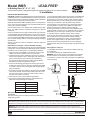
INLET
LIPS
SLOPING
INWARD
CORRECT ORIENTATION
OF WBR GASKET IN BELL
CONNECTION
TO STREET
WATER MAIN
ZURN WILKINS MODEL
WBR
BUILDING
FOUNDATION
WBR
RESTRAINT
TYPICAL INSTALLATION
BUILDING WATER
SYSTEM
Installation
Model WBR LEAD-FREE*
In Building Riser (4”, 6”, 8”, 10")
1. Insure that the gasket surfaces and grooves of the WBR and
grooved pipe being attached are clean and free of nicks and
gouges that may cause the coupling to leak. Remove gasket
Remove gasket from grooved coupling by loosening and then
removing nuts and bolts. Lubricate gasket using lubricant
recommended by the manufacturer or a liquid soap solution.
2. Install gasket on coupling end of WBR. The edge of the
gasket should be ush or slightly below the pipe end.
3. Place grooved pipe end on grooved end of WBR and slide
coupling gasket onto pipe end. The gasket should be centered
between the groove in the pipe and the groove in the WBR.
4. Lubricate inside of coupling housings. Place coupling
housings over gasket. Some couplings only go together one
way so make sure housing halves are oriented correctly.
5. Install bolts and tighten nuts evenly. The housing halves
should come together solidly. If the gasket starts to pinch,
remove bolts and verify the gasket has not been damaged.
Lubricate inside ends of the housings again and attach housing
halves.
Placing Device in Service
1. Flush WBR with water to remove dirt and debris remaining
from installation.
2. If required, disinfect per AWWA standard C651.
WARNING: Do not allow chlorine concentration to exceed the
level and duration of test stated in the standard. Exceeding
concentration or duration will result in damage to the WBR and
void the warranty.
ISWBR (REV. D 4/16)
Proper performance is dependent upon licensed, qualied personnel performing regular, periodic testing according to ZURN WILKINS' specications
and prevailing governmental & industry standards and codes and upon following these installation instructions. Failure to do so releases ZURN
WILKINS of any liability that it might otherwise have with respect to that device. Such failure could also result in an improperly functioning device.
Size of WBR Maximum Deection
4" .5°
6" 1°
8" 1°
10" 1°
ZURN WILKINS
1747 Commerce Way, Paso Robles, CA 93446 Phone:855-663-9876 Fax:805-238-5766
INSTALLATION INSTRUCTIONS
CAUTION: Installation of In Building Risers must be performed by
qualied personnel. The installer should be sure the proper device
has been selected for the particular installation. Faulty installation
could result in an improperly functioning device.
ZURN WILKINS Model WBR In Building Risers are designed for
use to connect a water supply line from outside the building to the
water system inside the building.
Care should be taken not to damage ends of WBR during instal-
lation. The WBR should be restrained underground to prevent
movement.
Some soil conditions such as high chloride values, PH lower than
4.5 and resistivity less than 2000 ohm per cm can cause corrosion
of the stainless steel pipe not covered under warranty. Precautions,
such as wrapping the WBR should be taken to protect the WBR
from corrosion damage. Refer to local pipe and ttings wrapping
specications.
Always consult local codes for installation methods, approvals
and guidance.
Below Ground Connection - Push-on Gasketed Coupling
Either ductile iron or C900 PVC pipe may be connected to the WBR
underground. Connect piping to the WBR using industry standard
procedures such as those given in Uni-Bell piping handbook.
1. Clean out inside of the WRB. Insure that the bell end of the
WBR is free of dirt and debris to insure a good seal.
2. A gasket has been factory installed in the groove in the bell.
Insure that the gasket is clean, undamaged, fully seated in the
groove and facing the correct direction (see illustration).
Do not lubricate the outside of the gasket. Contact ZURN
WILKINS if a replacement gasket is required.
3. Insure that the mating pipe spigot has a factory spec bevel
produced by a pipe bevel tool, to prevent damaging the gasket
in the bell. Lubricate end of mating pipe with the appropriate
pipe joint lubricant.
4. Push lubricated end past gasket into the bell end of the WBR
until it is fully seated. The two tabs located on the side of the
bell end may be used in conjunction with a pulley to winch
the pipe into the bell if necessary.
5. Consult local codes for joint restraint requirements.
6. The maximum allowed pipe deection angle between the
WBR and underground pipe is as follows:
Replacement bell end gaskets
Size Part Number
4" IBR09-13
6" IBR10-13
8" IBR11-13
10" IBR12-13
®
www.zurn.com
*This product contains a weighted average lead content less than 0.25% for wetted surfaces.
®
Above Ground Connection - AWWA C606 Grooved
Connection
Use an IPS sized grooved coupling to attach the WBR to the
inside piping system.
WARNING: This product may contain a chemical known to the State of California to cause cancer, birth defects or other reproductive harm
ADVERTENCIA: Este producto puede contener una sustancia química que el Estado de California como causante de cáncer, defectos de nacimiento
y otros daños reproductivos.
-
 1
1

Zurn Wilkins 4-WBR Installation guide
- Type
- Installation guide
Ask a question and I''ll find the answer in the document
Finding information in a document is now easier with AI
Other documents
-
 Star Pipe Products SGDPPK10N Installation guide
-
LevelOne WBR-1101TX User manual
-
-
-
D-Link WBR-1310 - Wireless G Router User manual
-
LevelOne WBR-6803 Datasheet
-
Dlink WBR2310 - RangeBooster G Wireless Router User manual
-
-
-
