Page is loading ...

I-P100
FIELD INSTALLATION HANDBOOK
Victaulic
®
QuickVic
™
SD Installation-Ready
™
System
Contact Victaulic with any questions regarding the safe and proper installation
of products featured in this handbook.
Visit victaulic.com for the most up-to-date information on Victaulic products.
• PRODUCT INSTALLATION
• INSTALLATION INSPECTION
• HELPFUL INFORMATION
WARNING
• Read and understand all instructions before attempting to install, remove,
adjust, or maintain any Victaulic products.
• Always depressurize and drain the piping system before attempting to install,
remove, adjust, or maintain any Victaulic products.
• Wear safety glasses, hardhat, foot protection, and hearing protection.
Failure to follow instructions and warnings could cause system failure, resulting
in death or serious personal injury and property damage.

I-P100_i
TABLE OF CONTENTS REV_A
Table of Contents
GENERAL INFORMATION
HAZARD IDENTIFICATION ................................................................2
INTRODUCTION ...............................................................................2
IMPORTANT INFORMATION .............................................................3
GASKET SELECTION ......................................................................... 4
PIPING SUPPORT .............................................................................4
PIPE PREPARATION REQUIREMENTS ..............................................5
MINIMUM PIPE NIPPLE LENGTH REQUIREMENTS ..........................5
PIPE MARKING REQUIREMENTS .....................................................6
Using the PC3110 Cut and Mark Tool ...................................... 6
Using the Insertion Depth Indicators on an
Elbow or Tee Fitting ............................................................. 6
Using a Ruler or Measuring Tape ............................................. 6
LUBRICATION REQUIREMENTS .......................................................7
PIPE INSERTION REQUIREMENTS .............................................8 – 9
IMPACT WRENCH USAGE GUIDELINES..........................................10
INSTALLATION VERIFICATION ........................................................ 11
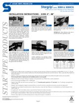
INSTALLATION INSTRUCTIONS
NO. P10 (90° ELBOW) QUICKVIC
™
SD INSTALLATION-READY
™
FITTING FOR PLAIN-END CARBON STEEL PIPE INSTALLATION
INSTRUCTIONS ......................................................................13 – 18
NO. P20 (STRAIGHT TEE) QUICKVIC
™
SD INSTALLATION-READY
™
FITTING FOR PLAIN-END CARBON STEEL PIPE INSTALLATION
INSTRUCTIONS ......................................................................19 – 28
STYLE P07 QUICKVIC
™
SD INSTALLATION-READY
™
COUPLING
FOR PLAIN-END CARBON STEEL PIPE INSTALLATION
INSTRUCTIONS ......................................................................29 – 32
STYLE P08 QUICKVIC
™
SD INSTALLATION-READY
™
SLIP COUPLING
FOR PLAIN-END CARBON STEEL PIPE INSTALLATION
INSTRUCTIONS ..................................................................... 33 – 38
STYLE P50 QUICKVIC
™
SD INSTALLATION-READY
™
REDUCING
COUPLING FOR PLAIN-END CARBON STEEL PIPE INSTALLATION
INSTRUCTIONS ......................................................................39 – 42
NO. P47 (STRAIGHT) AND NO. P97 (90° ELBOW)
DIELECTRIC ADAPTERS (PLAIN END X SWEAT) INSTALLATION
INSTRUCTIONS ..................................................................... 43 – 44
SERIES P89 BALL VALVE INSTALLATION AND
HANDLE EXTENSION KIT INSTRUCTIONS .............................45 – 46

I-P100_ii TABLE OF CONTENTS REV_A
REUSE INSTRUCTIONS
QUICKVIC
™
SD INSTALLATION-READY
™
SYSTEM
PRODUCTS REUSE INSTRUCTIONS .......................................47 – 58
PRODUCT DATA
PRODUCT DATA .....................................................................59 – 66
HELPFUL INFORMATION
ENGLISH TO METRIC CONVERSION CHART ..................................68
METRIC TO ENGLISH CONVERSION CHART ..................................68
DECIMAL EQUIVALENTS OF FRACTIONS .......................................69
PRESSURE TO FEET-OF-HEAD OF WATER ..................................... 70
FEET-OF-HEAD OF WATER TO PRESSURE ..................................... 70
PRESSURE TO METER WATER COLUMN .......................................71
METER WATER COLUMN TO PRESSURE .......................................71
WHERE TO FIND INSTALLATION INSTRUCTIONS
FOR ADDITIONAL PRODUCTS ................................................72 – 75

I-P100_1
General
Information

I-P100_2 GENERAL INFORMATION REV_A
HAZARD IDENTIFICATION
Definitions for identifying the various hazard levels are provided below.
This safety alert symbol indicates important safety messages. When you
see this symbol, be alert to the possibility of personal injury. Carefully read
and fully understand the message that follows.
DANGER
• The use of the word “DANGER”
identifies an immediate hazard
with a likelihood of death or serious
personal injury if instructions,
including recommended
precautions, are not followed.
WARNING
• The use of the word “WARNING”
identifies the presence of hazards
or unsafe practices that could
result in death or serious personal
injury if instructions, including
recommended precautions, are not
followed.
CAUTION
• The use of the word “CAUTION”
identifies possible hazards or
unsafe practices that could result
in personal injury and product or
property damage if instructions,
including recommended
precautions, are not followed.
NOTICE
• The use of the word “NOTICE”
identifies special instructions that
are important but not related to
hazards.
INTRODUCTION
This I-P100 Field Installation Handbook contains important information regarding pipe
preparation and installation of Victaulic
®
QuickVic
™
SD Installation-Ready
™
System
products for carbon steel pipe.
In addition to this I-P100, Victaulic offers field installation handbooks, installation sheets,
or installation tags for mechanical piping products that join alternate piping materials
or that work with other dedicated groove profile technologies. These instructions are
shipped with the applicable product and can be downloaded at victaulic.com.
Always follow good piping practices. Specified pressures, temperatures, external loads,
internal loads, performance standards, and tolerances shall never be exceeded.
Many applications require recognition of special conditions, code requirements, and the
use of safety factors. Qualified engineers shall reference Victaulic publication 05.01,
“Seal Selection Guide,” when determining requirements for special applications. This
publication can be downloaded at victaulic.com.
SCAN QR CODE FOR ADDITIONAL
FIELD INSTALLATION HANDBOOKS
THAT VICTAULIC OFFERS

I-P100_3GENERAL INFORMATION REV_A
NOTICE
• Victaulic maintains a continual policy of product improvement. Therefore,
Victaulic reserves the right to change product specifications, designs, and
standard equipment without notice and without incurring obligation.
• VICTAULIC IS NOT RESPONSIBLE FOR SYSTEM DESIGN, NOR DO THEY
ASSUME ANY RESPONSIBILITY FOR SYSTEMS THAT ARE DESIGNED
IMPROPERLY.
• This handbook is not intended to be a substitute for competent, professional
assistance, which is a prerequisite for any product application.
• The information published in this handbook and other Victaulic literature
supersedes all previously published information.
• Drawings and/or pictures in this manual may be exaggerated for clarity.
• The field installation handbook contains trademarks, copyrights, and products
with patented features that are the exclusive property of Victaulic.
• WHILE EVERY EFFORT HAS BEEN MADE TO ENSURE ITS ACCURACY,
VICTAULIC, ITS SUBSIDIARIES, AND ITS AFFILIATED COMPANIES MAKE
NO EXPRESSED OR IMPLIED WARRANTY OF ANY KIND REGARDING THE
INFORMATION CONTAINED OR REFERENCED IN THIS HANDBOOK. ANYONE
WHO USES THE INFORMATION CONTAINED HEREIN DOES SO AT THEIR RISK
AND ASSUMES ANY LIABILITY THAT RESULTS FROM SUCH USE.
IMPORTANT INFORMATION
QuickVic
™
SD Installation-Ready
™
products shall be used only for joining Schedules
10 – 80 carbon steel pipe (150 Brinell Hardness Number [BHN] maximum) in ½-inch/
DN15, ¾-inch/DN20, 1-inch/DN25, 1 ¼-inch/DN32, 1 ½-inch/DN40, and 2-inch/DN50
sizes. Refer to the table below for the allowable pipe outside diameter dimensions that
can be used with QuickVic
™
SD Installation-Ready
™
products.
For complete material specifications and application information, always reference
Victaulic publication 34.01, which can be downloaded at victaulic.com.
Allowable Pipe Outside Diameter Dimensions
Nominal
Diameter
inches/DN
Actual Pipe
Outside Diameter
inches/mm
Allowable Pipe Outside Diameter
Dimensions – inches/mm
Maximum Minimum
½ 0.840 0.855 0.825
DN15 21.3 21.7 21.0
¾ 1.050 1.065 1.035
DN20 26.9 27.1 26.3
1 1.315 1.330 1.300
DN25 33.7 33.8 33.0
1 ¼ 1.660 1.675 1.645
DN32 42.4 42.5 41.8
1 ½ 1.900 1.915 1.885
DN40 48.3 48.6 47.9
2 2.375 2.406 2.344
DN50 60.3 61.1 59.5
Canadian Customers – CSA B51 Compliance: For applications within the scope of CSA
B51, “Boiler, Pressure Vessel and Pressure Piping Code,” please contact Victaulic for the
most up-to-date Canadian Registration Numbers, approved products, and temperature
ratings.

I-P100_4 GENERAL INFORMATION REV_A
GASKET SELECTION
CAUTION
• Always specify the proper gasket material grade for the intended service.
Failure to select the proper gasket material grade for the service may cause joint
leakage, resulting in property damage.
Do not subject gaskets to temperatures beyond the specified limits. Excessive
temperatures will degrade gasket performance. Prior to product installation, check the
gasket to verify that it is suitable for the intended service. The color code identifies the
gasket grade. For complete information, always refer to Victaulic publication 05.01, “Seal
Selection Guide,” which can be downloaded at victaulic.com.
Gasket Color Code Reference
Grade Compound Color Code
EHP
EPDM Red and Green Stripes
T
Nitrile Orange Stripe
PIPING SUPPORT
WARNING
• These values are not intended to be used as specifications for all installations,
and they DO NOT apply where critical calculations are made or where there are
concentrated loads between supports.
• DO NOT use piping joined with QuickVic
™
SD Installation-Ready
™
products as a
lift point. DO NOT climb or hang on pipe joined with these products.
Failure to follow these instructions could cause joint failure, resulting in death or
serious personal injury and property damage.
Piping that is joined with QuickVic
™
SD Installation-Ready
™
products requires support to
carry the weight of pipes and equipment. The support or hanging method shall eliminate
stress on joints, piping, piping contents (fluids), and other components. In addition, the
method of support shall allow for pipeline movement, where required, along with other
design requirements, such as drainage.
The following tables list the suggested maximum span between pipe supports for
horizontal, straight runs of pipe carrying water or similar liquids.
Piping Support for Schedules 10 – 80 Carbon Steel Pipe
Nominal
inches/DN
Actual
Outside
Diameter
inches/mm
Suggested Maximum Span Between Supports
feet/meters
Water Service Air Service
B31.1 B31.9 B31.1 B31.9
½ 0.840 6 7 8 7
DN15 21.3 1.8 2.1 2.4 2.1
¾ 1.050 7 8 9 8
DN20 26.9 2.1 2.4 2.7 2.4
1 1.315 7 9 9 9
DN25 33.7 2.1 2.7 2.7 2.7
1 ¼ 1.660 7 11 9 11
DN32 42.4 2.1 3.4 2.7 3.4
1 ½ 1.900 7 12 9 13
DN40 48.3 2.1 3.7 2.7 4.0
2 2.375 10 13 13 15
DN50 60.3 3.1 4.0 4.0 4.6

I-P100_5GENERAL INFORMATION REV_A
PIPE PREPARATION REQUIREMENTS
ACCEPTABLE
The pipe OD shall not contain burrs, sharp edges,
raised weld beads, axial score marks, scratches, or
indentations a minimum of 2 inches/51 mm back
from the pipe end. All oil, grease, loose paint, dirt,
and cutting particles shall be removed.
BURRS AND SHARP
EDGES REMOVED
Pipe ends shall
be square cut
("S" dimension
shown) within
0.030 inch/0.8 mm.
"S" Max.
NOT ACCEPTABLE
Excessive chamfer on the pipe ID will cut
the gasket during assembly. Excessive
chamfer is not acceptable.
Abrasive wheels and saws will leave
edges on pipe ends that are pronounced
on one side. Burrs and sharp edges are
not acceptable.
Dull wheel cutters will push ridges up at
the pipe OD, resulting in an oversized
pipe diameter. Oversized pipe diameters
are not acceptable.
NOT ACCEPTABLE
NOT ACCEPTABLE
MINIMUM PIPE NIPPLE LENGTH REQUIREMENTS
WARNING
• Carbon steel pipe for use with QuickVic
™
SD Installation-Ready
™
products shall
meet the minimum pipe-nipple length requirements specified in the table below.
Failure to follow these instructions could cause joint failure, resulting in death or
serious personal injury and property damage.
QuickVic
™
SD Installation-Ready
™
products require that the pipe be inserted to the
appropriate depth to ensure satisfactory performance (refer to the “Insertion Depth
Requirements” table on the following page).
The following table provides the minimum length necessary to ensure adequate insertion
depth and clearance for back-to-back coupling/fitting installation. NOTE: Pipe nipple
lengths shorter than 3 ⁄ inches/86 mm will require manual marking of pipe (refer to the
“Insertion Depth Requirements” table on the following page).
Nominal
inches/DN
Actual Outside
Diameter
inches/mm
Minimum Pipe Nipple
Length Required
inches/mm
½ – 1 ¼ 0.840 – 1.660 2 ⁄
DN15 – DN32 21.3 – 42.4 60
1 ½ – 2 1.900 – 2.375 3 ⁄
DN40 – DN50 48.3 – 60.3 79

I-P100_6 GENERAL INFORMATION REV_A
PIPE MARKING REQUIREMENTS
WARNING
• Insertion depth shall be measured and marked on each pipe end for visual
confirmation that the pipe is inserted fully into the coupling or fitting.
Failure to follow this instruction could cause joint failure, resulting in death or
serious personal injury and property damage.
There are three methods that can be used to make the required insertion depth mark on
pipe for QuickVic
™
SD Installation-Ready
™
products.
Using the PC3110 Cut and Mark Tool
The Victaulic PC3110 Cut and Mark Tool is a portable tool
that operates with a power drive for preparing pipe to receive
QuickVic
™
SD Installation-Ready
™
products. The PC3110
tool is designed to cut and mark ½ – 2-inch/DN15 – DN50
Schedules 10 – 80 carbon steel pipe.
For complete setup and operating instructions for this tool,
refer to the TM-PC3110, which can be downloaded at
victaulic.com.
Insertion Depth Mark for
½ – 1¼-inch/DN15 – DN32
Product Sizes
Insertion Depth Mark for
1½ – 2-inch/DN40 – DN50
Product Sizes
The PC3110 automatically produces two knurled marks on
the pipe end at the required insertion depth.
The mark closest to the pipe end indicates the required
insertion depth for ½ – 1 ¼-inch/DN15 – DN32 product
sizes, as shown.
The second mark indicates the required insertion depth for
1 ½ – 2-inch/DN40 – DN50 product sizes, as shown.
Using the Insertion Depth Indicators on an Elbow or Tee Fitting
Each elbow or tee fitting contains
an insertion depth indicator at
each pipe insertion location, as
shown. Place the pipe end up
against the raised portion of the
fitting, and place a mark around
the entire pipe circumference
with a marker or paint pen at this
required insertion depth.
Using a Ruler or Measuring Tape
Refer to the table below for the insertion depth requirements.
Using a ruler or measuring tape, measure back from the
pipe end. Place a mark around the entire pipe circumference
with a marker or paint pen, as shown.
Insertion Depth Requirements
Nominal
inches/DN
Actual Outside
Diameter
inches/mm
Insertion Depth
Requirements
inches/mm
½ – 1 ¼ 0.840 – 1.660 1 ⁄
DN15 – DN32 21.3 – 42.4 29
1 ½ – 2 1.900 – 2.375 1 ½
DN40 – DN50 48.3 – 60.3 38

I-P100_7GENERAL INFORMATION REV_A
LUBRICATION REQUIREMENTS
CAUTION
• A thin coat of a compatible lubricant, such as Victaulic Lubricant or silicone
lubricant, shall be used on the pipe ends or sealing lips of the gasket to prevent
the gasket from pinching, rolling, or tearing during installation.
Failure to use a compatible lubricant will cause gasket damage, resulting in joint
leakage and property damage.
Lubrication of the pipe ends or sealing lips of the gasket with a thin coating of a
compatible lubricant, such as Victaulic Lubricant or silicone lubricant, is required to
prevent the gasket from pinching, rolling, or tearing during product installation. In
addition, lubrication eases installation of the gasket onto the pipe end. Refer to Victaulic
publication 05.02 for the Victaulic Lubricant Safety Data Sheet (SDS), which can be
downloaded at victaulic.com.

I-P100_8 GENERAL INFORMATION REV_A
PIPE INSERTION REQUIREMENTS
½ – 1 ¼-inch/DN15 – DN32 Product Sizes Marked with the
PC3110 Cut and Mark Tool
Prior to tightening any hardware, verify that the pipe marks indicate full insertion into the
coupling or fitting, as shown in the examples below.
Insertion Depth Mark for
½ – 1¼-inch/DN15 – DN32
Product Sizes
Insertion Depth Mark for
1½ – 2-inch/DN40 – DN50
Product Sizes
BAD
GOOD
BAD
GOOD
Example P10 Example P20
1 ½ – 2-inch/DN40 – DN50 Product Sizes Marked with the
PC3110 Cut and Mark Tool
Prior to tightening any hardware, verify that the pipe marks indicate full insertion into the
coupling or fitting, as shown in the examples below.
Insertion Depth Mark for
½ – 1¼-inch/DN15 – DN32
Product Sizes
Insertion Depth Mark for
1½ – 2-inch/DN40 – DN50
Product Sizes
BAD
GOOD
BADBAD
Example P10 Example P10

I-P100_9GENERAL INFORMATION REV_A
PIPE INSERTION REQUIREMENTS (CONTINUED)
Pipe Marked by Using a Marker or Paint Pen
Prior to tightening any hardware, verify that the pipe marks indicate full insertion into the
coupling or fitting, as shown in the examples below.
BAD
GOOD
Example P10
GOOD
BAD
Example P50 Example P50

I-P100_10 GENERAL INFORMATION REV_A
IMPACT WRENCH USAGE GUIDELINES
WARNING
• The nut shall be tightened until metal-to-metal c ontact occurs at the bolt pads.
• DO NOT continue to tighten the hardware after the visual installation guidelines
for the product, described in the applicable installation section of this
handbook, are achieved.
Failure to follow these instructions could cause joint failure, resulting in death or
serious personal injury and property damage.
Impact wrenches do not provide the installer with direct “wrench feel” or torque to judge
nut tightness. Since some impact wrenches are capable of high output, it is important
to develop a familiarity with the impact wrench to avoid damaging or fracturing the bolts
or the bolt pads during installation. Always choose the right size impact wrench that
has enough power, but DO NOT continue to tighten the hardware after the visual
installation guidelines for the product, described in the applicable installation section
of this handbook, are achieved. If you suspect that any hardware has been over-
tightened (as indicated by a bend or crack in the bolt, etc.), the hardware shall be
replaced immediately.
If the battery is drained or if the impact wrench is under-powered, a new battery pack or
new impact wrench shall be used to ensure that the visual installation guidelines for the
product, described in the applicable installation section of this handbook, are achieved.
Visual inspection of each joint is required for verification of proper assembly.
Perform trial assemblies with the impact wrench and check the assemblies with a torque
wrench to help determine the suitability of the impact wrench. Using the same method,
periodically check assemblies throughout the system installation.
For safe and proper use of impact wrenches, always refer to the impact wrench
manufacturer’s operating instructions. In addition, verify that proper impact grade sockets
are being used for coupling installation.
WARNING
Failure to follow instructions for tightening hardware could result in:
• Personal injury or death
• Bolt damage or fracture
• Damaged or broken bolt pads or fractures to housings
• Joint leakage and property damage

I- P100_11GENERAL INFORMATION REV_A
INSTALLATION VERIFICATION
Prior to initial system test, verify that the following installation requirements have been
achieved.
Verify that Pipe Marks Indicate Full Insertion Into the Coupling or Fitting – Refer to the
“Pipe Insertion Requirements” section on pages 8 – 9 for examples.
Verify that Metal-To-Metal Bolt Contact is Achieved at Each Bolt Pad – Refer to
the applicable installation section of this manual for examples. If metal-to-metal bolt
pad contact cannot be achieved, verify that the pipe tolerances are within Victaulic
specifications. Contact Victaulic with any questions concerning installation.
Verify that Retainers are Installed Within the Housings – QuickVic
™
SD Installation-
Ready
™
couplings and fittings contain “windows” that can be used to verify the presence
of retainers after the product is installed on pipe. If a retainer is not visible through
a window after the product is installed on pipe: If a retainer is missing, the coupling
or fitting shall be removed so that a retainer can be installed (refer to the “Reuse
Instructions” section starting on page 47 of this handbook), or the coupling or fitting shall
be removed and replaced completely.
Window Window
WARNING
• Always depressurize and drain the piping system before
attempting to install, remove, adjust, or maintain any
Victaulic piping products.
Failure to follow this instruction could result in death or serious
personal injury and property damage.
Patented “Leak-if-Not-Tightened” Technology – QuickVic
™
SD Installation-Ready
™
products are designed with a feature that will allow the joint to leak during an initial
system test (following the first assembly of the product on pipe) if the hardware is not
tightened adequately. If any leakage occurs during the initial system test, the system shall
be depressurized and drained completely so that the installer can tighten the hardware to
achieve metal-to-metal bolt pad contact or to correct any other misassembly condition.

I-P100_12 GENERAL INFORMATION REV_A

I-P100_13
No. P10 (90° Elbow)
QuickVic
™
SD
Installation-Ready
™
Fitting for Plain-End
Carbon Steel Pipe
Installation Instructions

I-P100_14
QUICKVIC
™
SD INSTALLATION-READY
™
SYSTEM
FOR PLAIN-END CARBON STEEL PIPE
INSTALLATION INSTRUCTIONS REV_A
DO NOT REMOVE
NUT/BOLT FOR INITIAL
INSTALLATION
DO NOT DISASSEMBLE THE NO. P10 FOR
INITIAL INSTALLATION: The No. P10 is
designed so that the installer does not need
to remove the bolts and nuts for installation.
This facilitates assembly by allowing the
installer to directly install the No. P10 onto
marked plain-end pipe.
WARNING
• Never leave a No. P10 partially assembled. ALWAYS TIGHTEN THE HARDWARE
IMMEDIATELY. A partially assembled No. P10 poses a drop or fall hazard during
installation and a burst hazard during testing.
• Keep hands away from the opening of the No. P10 when attempting to insert
marked plain-end pipe. Retainer teeth are sharp and may cause injury.
Failure to follow these instructions could result in serious personal injury and
property damage.
No. P10 (90° Elbow) – QuickVic
™
SD Installation-Ready
™
Fitting for
Plain-End Carbon Steel Pipe
WARNING
• Read and understand all instructions before attempting to install, remove,
adjust, or maintain any Victaulic piping products.
• Always depressurize and drain the piping system before attempting to install,
remove, adjust, or maintain any Victaulic piping products.
• Wear safety glasses, hardhat, and foot protection.
Failure to follow these instructions could result in death or serious personal injury
and property damage.
Verify that the following instructions in the
“General Information” section have been followed:
Pipe Preparation Requirements
Minimum Pipe Nipple Length Requirements
Pipe Marking Requirements
Lubrication Requirements

I-P100_15
QUICKVIC
™
SD INSTALLATION-READY
™
SYSTEM
FOR PLAIN-END CARBON STEEL PIPE
INSTALLATION INSTRUCTIONS REV_A
INSTALLATION METHOD 1
1. INSERT FIRST PIPE END: Assemble the
joint by inserting a marked plain-end pipe
into one opening of the No. P10. Verify that
the pipe is inserted until the mark indicates
full insertion into the fitting, as shown. Refer
to the “Pipe Insertion Requirements” section
on pages 8 – 9.
1a. TIGHTEN NUT AT FIRST OUTSIDE
LOCATION: Using an impact wrench or
standard socket wrench with a deep-well
socket, tighten the nut at the corresponding
location until metal-to-metal contact occurs
at the bolt pad. Verify that the pipe mark
indicates full insertion into the fitting and
that the oval neck of the bolt seats properly
in the bolt hole. Refer to the “No. P10
Helpful Information” table on the following
page and the “Impact Wrench Usage
Guidelines” section on page 10.
GOOD
BAD
OVAL NECK OF BOLT SEATED PROPERLY OVAL NECK OF BOLT NOT SEATED PROPERLY
WARNING
• At this point, the fitting is only partially installed.
• The fitting shall be treated as a potential drop hazard and shall not be left
unattended.
Failure to follow these instructions could result in death or serious personal injury
and property damage.
2. INSERT SECOND PIPE END: Insert
the second marked plain-end pipe into the
other opening of the fitting. Verify that the
pipe is inserted until the mark indicates full
insertion into the fitting. Refer to the “Pipe
Insertion Requirements” section on pages
8 – 9.
2a. COMPLETELY TIGHTEN NUT AT
INSIDE LOCATION: Completely tighten
the nut at the corresponding location until
metal-to-metal contact occurs at the bolt
pad. Verify that the pipe marks indicate full
insertion into the fitting and that the oval
neck of the bolt seats properly in the bolt
hole.

I-P100_16
QUICKVIC
™
SD INSTALLATION-READY
™
SYSTEM
FOR PLAIN-END CARBON STEEL PIPE
INSTALLATION INSTRUCTIONS REV_A
3. COMPLETELY TIGHTEN NUT AT
SECOND OUTSIDE LOCATION: Completely
tighten the nut at the corresponding location
until metal-to-metal contact occurs at the
bolt pad. Verify that the pipe marks indicate
full insertion into the fitting and that the
oval neck of the bolt seats properly in the
bolt hole.
4. COMPLETELY TIGHTEN NUT AT
FIRST OUTSIDE LOCATION: Go back and
completely tighten the nut at the first outside
location to confirm metal-to-metal contact
at the bolt pads. Verify that the pipe marks
indicate full insertion into the fitting and that
the oval neck of each bolt seats properly in
the bolt hole.
WARNING
• Nuts shall be tightened in the sequence shown on pages 15 – 16 until metal-to-
metal c ontact occurs at all bolt pads.
Failure to follow instructions for tightening hardware could result in:
• Personal injury or death
• Bolt damage or fracture
• Damaged or broken bolt pads or fractures to housings
• Joint leakage and property damage
NO. P10 HELPFUL INFORMATION
Nominal
inches/DN
Actual Outside
Diameter
inches/mm
Bolt Size
inches/Metric
Deep-Well
Socket Size
inches/mm
½– 1 ½ 0.840 ⁄ ⁄
DN15 – DN40 21.3 M10 17
2 2.375 ⁄ ⁄
DN50 60.3 M11 17

I-P100_17
QUICKVIC
™
SD INSTALLATION-READY
™
SYSTEM
FOR PLAIN-END CARBON STEEL PIPE
INSTALLATION INSTRUCTIONS REV_A
INSTALLATION METHOD 2
1. When practical, both marked plain-end
pipes may be inserted into the fitting prior
to tightening. In this case, the hardware
shall be tightened evenly by alternating
sides until the installation requirements
listed in these instructions are achieved.
WARNING
• Visual inspection of each joint is required.
• Improperly assembled joints shall be corrected before the system is tested or
placed into service.
• Any components that exhibit physical damage due to improper assembly shall
be replaced.
Failure to follow these instructions could cause joint failure, resulting in death or
serious personal injury and property damage.
GOOD
BAD
5. VERIFY THAT ALL NUTS ARE TIGHTENED COMPLETELY AND THAT METAL-TO-
METAL CONTACT IS ACHIEVED AT ALL BOLT PADS: Visually inspect all bolt pads at
each joint to verify that metal-to-metal contact is achieved.
/