Carrier HUMCCLFP1025-A User manual
- Category
- Dehumidifiers
- Type
- User manual
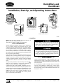
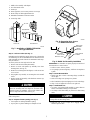
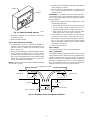
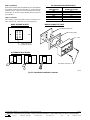
Carrier HUMCCLFP1025-A is a fan-powered humidifier designed for installation on the supply plenum of a forced-air system. It requires an external 115V power source and features a humidistat for precise humidity control. The unit is easy to install and maintain, with a removable pad that can be accessed from either the top or bottom of the unit.
Carrier HUMCCLFP1025-A is a fan-powered humidifier designed for installation on the supply plenum of a forced-air system. It requires an external 115V power source and features a humidistat for precise humidity control. The unit is easy to install and maintain, with a removable pad that can be accessed from either the top or bottom of the unit.


-
 1
1
-
 2
2
-
 3
3
-
 4
4
-
 5
5
-
 6
6
-
 7
7
-
 8
8
-
 9
9
-
 10
10
-
 11
11
-
 12
12


Carrier HUMCCLFP1025-A User manual
- Category
- Dehumidifiers
- Type
- User manual
Carrier HUMCCLFP1025-A is a fan-powered humidifier designed for installation on the supply plenum of a forced-air system. It requires an external 115V power source and features a humidistat for precise humidity control. The unit is easy to install and maintain, with a removable pad that can be accessed from either the top or bottom of the unit.
Ask a question and I''ll find the answer in the document
Finding information in a document is now easier with AI
Related papers
-
Carrier HUMXXSFP1012 Installation Instructions Manual
-
Presto HUMCCSFP1016-A Owner's manual
-
-
-
-
TOTALINE HUMCCLFP1218 Owner's manual
-
-
-
-
Other documents
-
Milwaukee 58-01-1270 User manual
-
 Skuttle Indoor Air Quality Products SK0-0055-001 User manual
-
Aprilaire Dehumidifier 4655 User manual
-
Bryant HUMBBLBP2018-A User manual
-
Hamilton M-300 Owner's manual
-
Air King 5000 Installation guide
-
York HU12MB Installation guide
-
 Speedi-Products SM-SDL45 08 Operating instructions
-
Honeywell HE120 User manual
-
Trion CM200 Flow-Through Humidifier User manual

