OFC

Danfoss OFC Installation guide

  • Hello, I have reviewed the provided installation guide for the Danfoss OFC 020R5421 check and stop valve. This document details the valve's installation requirements, including refrigerant compatibility, temperature and pressure limits, and orientation-specific spring changes. It also includes information on the use of stainless steel fasteners and provides specific torque values for installation. I'm ready to help answer any questions you may have about this valve.
  • What refrigerants are compatible with the OFC valve?
    What is the maximum working pressure for the OFC valve?
    What is the torque for the outlet flange fasteners?
    What type of bolts should be used for installation?
Installation guide
Check and Stop valve
Type OFC
© Danfoss | Climate Solutions | 2021.06 AN371420239255en-000102 | 1
Refrigerant:
UL listed for R134a, R513A and R515B. CE approved for fluid group 2, including R1234ze(E)
For other refrigerants, visit http://store.danfoss.com/ and search for individual code, where refrigerants are listed as part of product
details.
Oil: OFC valve is designed for an oil-free environment
Installation:
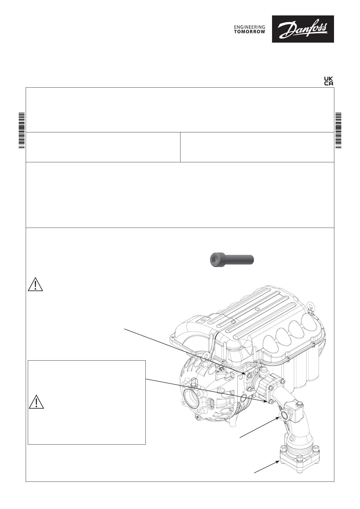
Install valve directly on Danfoss Turbocor compressor, picture shown with vertical down installation.
Protect the valve from impact in the installation.
All fasteners and bolts require stainless steel. Bolts with minimum class A2-70.
Media Temperature:
Min. 0 ⁰C / 32 ⁰F
Max. 90 ⁰C / 194 ⁰F, short term up to 100⁰C / 212⁰F
Contents of accessory box
Outlet flange for 3 1/8 in. copper tube
Outlet flange fasteners
O-ring for outlet flange
O-ring lubrication (2 gram)
Additional check valve springs (2 pcs):
- Yellow spring, for 45⁰ down orientation
- Red spring, for horizontal orientation
Max. Working Pressure:
PS/MWP = 23 bar / 334 psig
020R5421
020R5421
Staging Port:
Bolt size – M10x1.5
Torque: 38 Nm ± 4 Nm
Outlet Flange Fasteners:
Torque - 110 Nm
Ball valve clocking may be changed by removing
bolts and rotating ball valve housing without
retracting the ball valve assembly away from the
elbow.
NOTE: refer to check valve orientation options
below
Torque: 38 Nm ± 4 Nm
Reference specific compressor requirements
Info for UK customers only: Danfoss Ltd. Oxford Road, UB9 4LH Denham, UK.
NOTE: Protection of entire valve including steel
flange is recommended after installation for out-
door use.
020R5421
020R5421
© Danfoss | Climate Solutions | 2021.062 | AN371420239255en-000102
Outlet Flange Brazing:
Place outer flange on evenly cut copper pipe
NOTE: ensure flange is not mounted on main
housing during brazing
When changing check valve spring:
1. Remove check valve insert from main housing
2. Remove check valve head
3. Remove spring and replace with correct color based on in-
tended orientation
4. Replace check valve head and insert
5. Install outlet flange, O-ring and fasteners
Min 5% Ag
Main housing
Check valve insert
Check valve head
NOTE: Use silicone lubricant spray
at O-ring if needed
Check valve spring
Outlet flange,
O-ring and fasteners
NOTE: Apply provided lubrication to
O-ring
Always replace lock ring and cap after opening/ closing the
ball valve
Orientation:
NOTE: Check valve spring must be changed when using any
orientation other than vertical downing
Vertical down
Blue spring
(as delivered)
45° down
Yellow spri
ng
Horizontal
Red spring
45° up
Not allowed
45° up
Not allowed
Vertical up
Not allowed
45° down
Yellow spring
Horizontal
Red spring
Danfoss
20R01
/