Page is loading ...


Revision history Table of revisions
Date Changed Rev
October 2019 Fixed EDC control adjustments for clarity 0301
August 2019 Fixed typo 0202
July 2019 Various updates 0201
October 2018 Added Shaft Replacement 0106
July 2018 Fixed layout 0105
June 2018 Major Update 0104
October 2017 Added Size 130 0103
June 2016 Added Size 260 0102
April 2016 Converted to Danfoss layout - DITA CMS 0101
July 2015 Added 145 cc information AB
January 2014 First edition AA
Service Manual
D1 High Power Open Circuit Pumps Size 130/145/193/260
2 |
©
Danfoss | October 2019 L1527453 | AX00000292en-000301

Introduction
Overview..............................................................................................................................................................................................5
General instructions........................................................................................................................................................................ 5
Remove the unit..........................................................................................................................................................................5
Keep it clean..................................................................................................................................................................................5
Replace all O-rings and gaskets............................................................................................................................................. 5
Secure the unit.............................................................................................................................................................................5
Safety precautions............................................................................................................................................................................5
Unintended Machine Movement..........................................................................................................................................5
Flammable Cleaning Solvents................................................................................................................................................6
Fluid Under Pressure..................................................................................................................................................................6
Personal Safety.............................................................................................................................................................................6
Symbols used in Danfoss literature............................................................................................................................................6
Design...................................................................................................................................................................................................6
Cross-section view........................................................................................................................................................................... 8
Operation
NPNN (Pressure Compensated Control).................................................................................................................................. 9
NPSN (Pressure Compensated Control + Load Sensing Control).................................................................................11
NPNR (Pressure Compensated Control + Remote Pressure Compensated Control)............................................ 13
TPSN (Power Control + Pressure Compensated Control + Load Sensing Control)................................................15
NNES (Electric Displacement Control + Load Sensing Control)....................................................................................17
Solenoid Specification............................................................................................................................................................ 19
Standard EDC Valve................................................................................................................................................................. 20
NNES Priority.............................................................................................................................................................................. 20
TPE2/TPE5 (Power Control + Pressure Compensated Control + Electric Displacement Control).................... 21
TPE2/TPE5 Priority....................................................................................................................................................................21
NPE2/NPE0 (Pressure Compensated Control + Electric Displacement Control).....................................................22
Operating parameters
Pressure............................................................................................................................................................................................. 23
Speed..................................................................................................................................................................................................23
Fluid.................................................................................................................................................................................................... 23
Viscosity........................................................................................................................................................................................24
Temperature...............................................................................................................................................................................24
Fluid velocity.............................................................................................................................................................................. 24
Technical specifications
D1 130-260 pump specifications..............................................................................................................................................25
D1P fluid specifications................................................................................................................................................................26
Fluid and filter maintenance
Recommendations of Fluid and Filter Maintenance.........................................................................................................27
Pressure measurements
Port Locations and Gauge Installation (130/145)...............................................................................................................28
Port Locations and Gauge Instalation (193/260)................................................................................................................29
Initial start-up procedures
General...............................................................................................................................................................................................30
Start-up Procedure........................................................................................................................................................................30
Troubleshooting
Excessive Noise and /or Vibration............................................................................................................................................31
Low Pump Output Flow...............................................................................................................................................................31
No or Low System Pressure........................................................................................................................................................31
Actuator Response is Sluggish..................................................................................................................................................32
Pressure or Flow Instability.........................................................................................................................................................32
System Operating Hot..................................................................................................................................................................33
High Inlet Vacuum.........................................................................................................................................................................33
Adjustments
Calculate Power Control Start Point Pressure and Corresponding Flow in Advance........................................... 34
Service Manual
D1 High Power Open Circuit Pumps Size 130/145/193/260
Contents
©
Danfoss | October 2019 L1527453 | AX00000292en-000301 | 3

Electric Displacement Control Adjustment .........................................................................................................................35
Pressure Compensated Control Adjustment.......................................................................................................................37
Power Control Adjustment.........................................................................................................................................................37
Load Sensing Control Adjustment...........................................................................................................................................37
Displacement Limiters Adjustment.........................................................................................................................................40
Adjust Displacement Limiters..............................................................................................................................................40
Minor repairs
Shaft replacement......................................................................................................................................................................... 41
Shaft removal.............................................................................................................................................................................41
Shaft installation....................................................................................................................................................................... 42
Shaft Seal Replacement...............................................................................................................................................................43
Removal........................................................................................................................................................................................43
Installation...................................................................................................................................................................................43
Auxiliary Flange and Charge Pump Replacement............................................................................................................. 44
Auxiliary flange removal........................................................................................................................................................ 44
Auxiliary flange installation...................................................................................................................................................44
130/145........................................................................................................................................................................................ 45
193/260........................................................................................................................................................................................ 46
Control (193/260)...........................................................................................................................................................................47
Removal........................................................................................................................................................................................47
Installation...................................................................................................................................................................................47
Control (130/145)...........................................................................................................................................................................49
Shuttle Valve or Plug.....................................................................................................................................................................50
Shuttle valve or plug removal..............................................................................................................................................50
Shuttle valve or plug installation........................................................................................................................................50
Edge Filter (260)..............................................................................................................................................................................50
Edge filter removal...................................................................................................................................................................50
Edge filter installation.............................................................................................................................................................50
Displacement Limiters................................................................................................................................................................. 52
Displacement limiter screw removals...............................................................................................................................52
Displacement limiter screws installation......................................................................................................................... 52
Plug and fitting installation........................................................................................................................................................54
193 TPE2 control.......................................................................................................................................................................54
260 TPE2 control.......................................................................................................................................................................55
130/145 TPSN control............................................................................................................................................................. 56
Plugs and fasteners....................................................................................................................................................................... 57
Fastener and torque chart.....................................................................................................................................................57
Plug size and torque chart.....................................................................................................................................................58
Service Manual
D1 High Power Open Circuit Pumps Size 130/145/193/260
Contents
4 |
©
Danfoss | October 2019 L1527453 | AX00000292en-000301

Pump service overview
This manual includes information on maintenance, troubleshooting, and minor repair of D1P pumps.
Performing minor repairs may require removal from the vehicle/machine. Thoroughly clean the unit
before beginning maintenance or repair activities. Since dirt and contamination are the greatest enemies
of any type of hydraulic equipment, follow cleanliness requirements strictly. This is especially important
when changing the system filter and when removing hoses or plumbing.
A worldwide Global Service Partner Network is available for major repairs. Major repairs require the
removal of the unit’s endcap, which voids the warranty unless done by a Global Service Partner. Danfoss
Global Service Partners are trained by the factory and certified on a regular basis. You can locate your
nearest Global Service Partner using the distributor locator at www.danfoss.com.
For detailed technical information, refer to the Technical Information manual.
General instructions
Remove the unit
If necessary, remove the unit from the vehicle/machine. Chock the wheels on the vehicle or lock the
mechanism to inhibit movement. Be aware that hydraulic fluid may be under high pressure and/or hot.
Inspect the outside of the pump and fittings for damage. Cap hoses after removal to prevent
contamination.
Keep it clean
Cleanliness is a primary means of assuring satisfactory pump life on either new or repaired units.
Clean the outside of the pump thoroughly before disassembly. Take care to avoid contamination of the
system ports. Cleaning parts by using a clean solvent wash and air drying is usually adequate.
As with any precision equipment, you must keep all parts free of foreign material and chemicals. Protect
all exposed sealing surfaces and open cavities from damage and foreign material. If left unattended,
cover the pump with a protective layer of plastic.
Replace all O-rings and gaskets
Danfoss recommends that you replace all O-rings, seals and gaskets. Lightly lubricate all O-rings with
clean petroleum jelly prior to assembly.
Secure the unit
If removed from machine, place the unit in a stable position with the shaft pointing downward. It
will be necessary to secure the pump while removing and torquing fasteners and components.
Safety precautions
Unintended Machine Movement
Unintended movement of the machine or mechanism may cause injury to the technician or bystanders.
Secure the machine or disable/disconnect the mechanism while servicing to protect against unintended
movement.
Service Manual
D1 High Power Open Circuit Pumps Size 130/145/193/260
Introduction
©
Danfoss | October 2019 L1527453 | AX00000292en-000301 | 5

Flammable Cleaning Solvents
Some cleaning solvents are flammable.
Do not use cleaning solvents in an area where a source of ignition may be present to avoid possible fire.
Fluid Under Pressure
Escaping hydraulic fluid under pressure can have sufficient force to penetrate your skin causing serious
injury and/or infection. This fluid may also be hot enough to cause burns.
Relieve pressure in the system before removing hoses, fittings, gauges, or components. Never use your
hand or any other body part to check for leaks in a pressurized line. Use caution when dealing with
hydraulic fluid under pressure. Seek medical attention immediately if you are cut by hydraulic fluid.
Personal Safety
Protect yourself from injury whenever servicing a hydraulic system.
Use proper safety equipment, including safety glasses, at all times.
Symbols used in Danfoss literature
WARNING may result in injury Tip, helpful suggestion
CAUTION may result in damage to product or
property
Lubricate with hydraulic fluid
Reusable part Apply grease / petroleum jelly
Non-reusable part, use a new part Apply locking compound
Non-removable item Inspect for wear or damage
Option - either part may exist Clean area or part
Superseded - parts are not interchangeable Be careful not to scratch or damage
Measurement required Note correct orientation
Flatness specification Mark orientation for reinstallation
Parallelism specification Torque specification
External hex head Press in - press fit
Internal hex head Pull out with tool – press fit
Torx head Cover splines with installation sleeve
O-ring boss port Pressure measurement/gauge location or
specification
The symbols above appear in the illustrations and text of this manual. They are intended to communicate
helpful information at the point where it is most useful to the reader. In most instances, the appearance
of the symbol itself denotes its meaning. The legend above defines each symbol and explains its purpose.
D1 pumps design
Danfoss D1 high power open circuit piston pumps convert input torque into hydraulic power. Rotational
force is transmitted through the input shaft to the cylinder block. The input shaft is supported by roller
Service Manual
D1 High Power Open Circuit Pumps Size 130/145/193/260
Introduction
6 |
©
Danfoss | October 2019 L1527453 | AX00000292en-000301

bearings at the front and rear of the pump and is splined into the cylinder block . A lip-seal at the front
end of the pump prevents leakage where the shaft exits the pump housing. The spinning cylinder block
contains nine reciprocating pistons. Each piston has a brass slipper connected at one end by a ball joint.
The slippers are held to the swashplate by the retainer. The block spring holds the cylinder block to the
valve plate. The reciprocating movement of the pistons occurs as the slippers slide against the inclined
swashplate during rotation. Via the valve plate, one half of the cylinder block is connected to pump inlet
and the other half to pump outlet. As each piston cycles in and out of its bore, fluid is drawn from the
inlet and displaced to the outlet thereby imparting power into the system circuit. A small amount of fluid
is allowed to “leak” from the cylinder block / valve plate and slipper / swashplate interfaces for lubrication
and cooling. Case drain ports are provided to return this fluid to the reservoir.
The volume of fluid displaced into the system circuit is controlled by the angle of the swashplate. The
swashplate is forced into an inclined position (into stroke) by the bias piston and spring. The servo piston
opposes the action of the bias piston and spring forcing the swashplate out of stroke.
The pump control, by varying the pressure at the servo piston, controls the displacement of fluid in the
system circuit.
Service Manual
D1 High Power Open Circuit Pumps Size 130/145/193/260
Introduction
©
Danfoss | October 2019 L1527453 | AX00000292en-000301 | 7

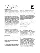
D1 pump cross-section view
D1 pump
1
2
3
4
5
6
7
8
9
10
11
12
13
14
15
16
1. Shaft seal
2. Roller bearing
3. Housing
4. Minimum displacement limiter
5. Bias piston
6. Control
7. Valve plate
8. Endcap
9. Charge pump
10. Servo piston
11. Cylinder block
12. Maximum displacement limiter
13. Piston
14. Swashplate
15. Swashplate Bearing
16. Input shaft
Some internal parts may be different depending on the pump size.
Service Manual
D1 High Power Open Circuit Pumps Size 130/145/193/260
Introduction
8 |
©
Danfoss | October 2019 L1527453 | AX00000292en-000301

NPNN (Pressure Compensated Control)
D1P 130/145/193/260+NPNN
Pressure Compensated Control (P) Principle
The P control design maintains a constant pressure in the hydraulic circuit as flow varies. The P control
modulates pump flow accordingly to maintain system pressure at the P setting as the P adjusting screw
and spring defines.
Pressure Compensated Control (P) Operation
When system pressure, acting on the non-spring end of the P spool, overcomes the force of the P spring,
the spool shifts porting system pressure to the servo piston and the swashplate angle decreases. When
system pressure drops below the P setting, the P spring shifts the spool in the opposite direction
connecting the servo piston to pump case and the swashplate angle increases. The swashplate is
maintained at whatever angle is required to keep system pressure at the P setting.
P characteristic
0
0
Q max
Flow
Pressure
It is recommended that a relief valve be installed in the pump outlet for additional system protection.
Service Manual
D1 High Power Open Circuit Pumps Size 130/145/193/260
Operation
©
Danfoss | October 2019 L1527453 | AX00000292en-000301 | 9

Response/Recovery
Pressure Compensated (PC) Control Response/Recovery Times* @80°C, 350 bar, 1500rpm
Frame Size Response (msec) Recovery (msec)
130cc 150 270
145cc 150 270
193cc
1
280 500
260cc 154 327
1
Tested at 1800rpm
Values may vary depending on application conditions. For more information, please contact Danfoss
Power Solutions.
Service Manual
D1 High Power Open Circuit Pumps Size 130/145/193/260
Operation
10 |
©
Danfoss | October 2019 L1527453 | AX00000292en-000301

NPSN (Pressure Compensated Control + Load Sensing Control)
D1P 130/145/193/260+NPSN
Pressure Compensated Control (P) Principle and Operation
Please refer to NPNN (Pressure Compensated Control) on page 9
Load Sensing Control (S) Principle
The S control design matches pump flow with system demand. The S control senses the flow demand of
the system as a pressure drop across the external control valve (1).
As (1) opens and closes, the pressure difference (delta) across the valve changes. When opening, the delta
decreases. When closing, the delta increases. The S control then increases or decreases pump flow to the
system until the pressure delta becomes equal to the S setting as defined by the S adjusting screw and
spring.
Load Sensing Control (S) Operation
Through internal porting, system pressure [upstream of (1)] is applied to the non-spring end of the S
spool, and through hydraulic line connected at port X, load pressure [downstream of (1)] is applied to the
spring end. This arrangement allows the S spool to act on the delta between system pressure and load
pressure. The S spring sets the threshold of operation (S setting).
Because the swashplate is biased to maximum angle, the pump attempts to deliver full flow to the
hydraulic system. When the flow being delivered exceeds demand, the pressure delta across the (1) is
great enough to overcome spring force and shift the S spool porting system pressure to the servo piston.
The pump de-strokes reducing flow until the delta across the (1) becomes equal to the S setting.
When flow being delivered is less than demand, the delta across the (1) drops below the S setting and the
S spring shifts the spool connecting the servo piston to pump case. The pump strokes increasing flow
until the delta across the (1) becomes equal to the S setting.
When the external control valve (1) is placed in neutral, it connects the LS signal line to drain. With no LS
pressure acting on the non-spring end of the LS spool, the pump adjusts stroke to whatever position
necessary to maintain system pressure at the LS setting. The pump is now in low pressure standby mode.
(1) is not in the scope of supply.
Service Manual
D1 High Power Open Circuit Pumps Size 130/145/193/260
Operation
©
Danfoss | October 2019 L1527453 | AX00000292en-000301 | 11

S characteristic
0
0
Q max
Flow
Pressure
P setting
For additional system protection, install a relief valve in the pump outlet line.
NPSN Priority
The Pressure Compensated Control (P) has priority over the Load Sensing Control (S).
Response/Recovery
Load Sensing (LS) Response/Recovery Times @80°C, 1500rpm, LS Setting at 25 bar
Frame Size Response (msec) Recovery (msec)
130cc 260 360
145cc 260 360
193cc
1
233 264
260cc 309 327
1
Tested with a LS setting of 20bar
Values may vary depending on application conditions. For more information, please contact Danfoss
Power Solutions
Service Manual
D1 High Power Open Circuit Pumps Size 130/145/193/260
Operation
12 |
©
Danfoss | October 2019 L1527453 | AX00000292en-000301

NPNR (Pressure Compensated Control + Remote Pressure Compensated Control)
D1P 130/145/193/260+NPNR
Pressure Compensated Control (P) Principle and Operation
Please refer to NPNN (Pressure Compensated Control) on page 9.
Remote Pressure Compensated Control (R) Principle
The remote PC control is a two-stage control that allows multiple PC settings. Remote PC controls are
commonly used in applications requiring low and high pressure PC operation.
For this control, Danfoss recommends a load sense setting of 20bar.
Remote Pressure Compensated Control (R) Operation
The remote PC control uses a pilot line connected to an external hydraulic valve. The external valve
changes pressure in the pilot line, causing the PC control to operate at a lower pressure. When the pilot
line is vented to reservoir, the pump maintains pressure at the load sense setting. When pilot flow is
blocked, the pump maintains pressure at the PC setting. An on-off solenoid valve can be used in the pilot
line to create a low-pressure standby mode. A proportional solenoid valve, coupled with a
microprocessor control, can produce an infinite range of operating pressures between the low pressure
standby setting and the PC setting.
R characteristic
0
0
Q max
Flow
Pressure
RP setting
PC setting
For additional system protection, install a relief valve in the pump outlet line.
Service Manual
D1 High Power Open Circuit Pumps Size 130/145/193/260
Operation
©
Danfoss | October 2019 L1527453 | AX00000292en-000301 | 13

NPNR Priority
When the pump’s X-port is vented to tank, or limited to some pressure setting via a remote valve, the
remote pressure compensator function will control the maximum outlet pressure of the pump. If the
pump’s outlet pressure reaches the pressure setting of the pressure compensator (PC) function, the PC
function will take priority and limit the pump’s maximum pressure.
Service Manual
D1 High Power Open Circuit Pumps Size 130/145/193/260
Operation
14 |
©
Danfoss | October 2019 L1527453 | AX00000292en-000301

TPSN (Power Control + Pressure Compensated Control + Load Sensing Control)
D1P 130/145+TPSN
X
MB
B
(1)
P400251
Vg min
Vg max
L3
S M4 L1 L2
D1P 193/260+TPSN
*Control oil filter is optional
P400080
X
Vg min
CW
Vg max
MB
B
L3
S M4 L1 L2
(1)
Power Control (T) Principle
The power control regulates the displacement of the pump depending on the working pressure so that a
given drive power is not exceeded at constant drive speed, this function can prevent engine stall or
protect electric generator.
P
B
= working pressure
P
B
• V
g
= C V
g
= displacement
C = constant
The precise control with a hyperbolic control characteristic, provides an optimum utilization of available
power.
Service Manual
D1 High Power Open Circuit Pumps Size 130/145/193/260
Operation
©
Danfoss | October 2019 L1527453 | AX00000292en-000301 | 15

Power Control (T) Operation
The working pressure acts on a rack-pivot via a roller jack which produces a rotating torque, an externally
adjustable spring force counteracts this which determines the power setting.
If the moment generated by working pressure exceeds the moment generated by spring force, the
control valve is actuated by the rack-pivot, and pump reduces displacement. The lever length at the rack-
pivot is shortened and the working pressure can increase at the same rate as the displacement decreases
without the drive powers being exceeded.
(P
B
• V
g
= C).
The hydraulic output power (characteristic T) is influenced by the efficiency of the pump.
T characteristic
Q max
0
0
Flow
Pressure
Pressure Compensated Control (P) Principle and Operation
Please refer to NPNN (Pressure Compensated Control) on page 9
Load Sensing Control (S) Principle and Operation
Please refer to NPSN (Pressure Compensated Control + Load Sensing Control) on page 11
TPSN Priority
The Pressure Compensated Control (P) has priority over the Power Control (T), Power Control has priority
over Load Sensing Control (S).
Service Manual
D1 High Power Open Circuit Pumps Size 130/145/193/260
Operation
16 |
©
Danfoss | October 2019 L1527453 | AX00000292en-000301

NNES (Electric Displacement Control + Load Sensing Control)
W
Warning
(1) Adjustment is not permissible
D1P 130/145/193/260 NNES
X
E
B
Vgmax Vgmin
B
MB
S
M4
L3
L1 L2
Electric Displacement Control (E) Principle
The electric displacement control uses an electric proportional solenoid valve to vary the pump’s
displacement from minimum displacement to maximum displacement or from maximum displacement
to minimum displacement. The swashplate angle (pump displacement) is proportional to the electrical
input signal (control current).
Electric Displacement Control (E) Operation
This control is current driven, requiring a Pulse Width Modulated (PWM) signal. Pulse width modulation
allows more precise control of current to the solenoid. The PWM signal causes the solenoid pin to push
against the E spool, which depressurizes the end of servo piston, the swashplate angle increases under
the force of the bias piston
A swashplate feedback link provides swashplate position force to the solenoid through the E spool’s
linear spring. The control reaches equilibrium when the position of the swashplate spring feedback force
exactly balances the input command solenoid force from the operator. As working pressure changes with
load, the control and servo/swashplate system work constantly to maintain the commanded position of
the swashplate.
Electric Displacement Control (E) Operating Instruction
To make sure the electric displacement control works properly, a minimum control pressure of 30 bar
[435 psi] is required. The required control pressure is taken either from the working pressure, or from the
externally applied control pressure at the E port.
If you can’t make sure that the working pressure is above 30 bar all the time, then a minimum of 30bar
[435 psi] pressure supply at the E port is mandatory in order to control the displacement of the pump at
all times. This pressure supply can be provided from different sources, such as an additional small gear or
piston pump and a relief valve, or an accumulator.
If E port is not connected, remove the shuttle valve
Service Manual
D1 High Power Open Circuit Pumps Size 130/145/193/260
Operation
©
Danfoss | October 2019 L1527453 | AX00000292en-000301 | 17

Typical operating curve
Hysteresis
EDC Hysteresis
1
Input hysteresis <4.5%
Output hysteresis @50% displacement <4.0%
1
Values may vary depending on application conditions. For more information, please contact Danfoss Power
Solutions
Response/Recovery
Response/Recovery Times @ 1500rpm (50°C)
1
Response 0%-100% 130cc (263 bar) 260 msec
145cc (263 bar) 260 msec
193cc (160 bar) 272 msec
260cc (200 bar) 370 msec
Response 100%-0% 130cc (263 bar) 390 msec
145cc (263 bar) 390 msec
193cc (160 bar) 186 msec
260cc (200 bar) 390 msec
MOR
Each Electric Displacement Control (EDC) is equipped with a Manual Over Ride (MOR) function for
temporary actuation of the control to aid in diagnostics, even if insufficient or no current is supplied to
the solenoid actuator. Initial activation of the MOR function will require a higher force to overcome the
sticking effect between the pin and O-ring seal. Repeated activation of this functionality should provide
better controllability.
Service Manual
D1 High Power Open Circuit Pumps Size 130/145/193/260
Operation
18 |
©
Danfoss | October 2019 L1527453 | AX00000292en-000301

W
Warning
Do not actuate the MOR unless the machine is in a “SAFE” mode. Unintended MOR operation will cause
the pump to go into stroke, use only for diagnosis purposes.
Solenoid Specification
Technical data - Solenoid
Voltage
24V (±20%)
Start current at Vg min.
200 mA
End Current at Vg max.
600 mA
Maximum current
770 mA
Coil Resistance @ 20 °C [70 °F]
22.7 Ω
PWM Range
70~200 Hz
PWM Frequency (preferred)
*
100 Hz
IP Rating (IEC 60 529) + DIN 40 050, part 9
IP 67
IP Rating (IEC 60 529) + DIN 40 050, part 9 with
mating connector
IP 69K
*
PWM signal required for optimum control performance
Mating connector for Solenoid
Description Ordering Number Quantity
Mating Connector DEUTSCH DT06-2S 1
Wedge Lock DEUTSCH W2S 1
Socket contact (16 and 18 AWG) DEUTSCH 0462-201-16141 2
Danfoss mating connector kit K29657 1
The mating connector is not included in the delivery contents, this can be delivered by Danfoss on request.
Compatible PLUS+1
®
controllers(see below):
MC012 L1301095
MC024 L1315302
MC038 11051653
MC050 L1301752
MC088 11006645
For further information: please visit: http://www.danfoss.com/Products/MobileElectronics/index.htm
Service Manual
D1 High Power Open Circuit Pumps Size 130/145/193/260
Operation
©
Danfoss | October 2019 L1527453 | AX00000292en-000301 | 19

Standard EDC Valve
The position of the connector can be changed by turning the solenoid body. Proceed as follows:
1. Loosen protection cap (1).
2. Loosen lock nut (2).
3. Turn the solenoid body (3) to the desired position.
4. Tighten the lock nut (2).
5. Tighten the protection cap (1).
Tightening Torque of lock nut: 5 ± 1 N•m [44.25 ± 8.85 lbf•in]
Standard EDC Valve
DEUTSCH DT04-2P
74.5 4.5
(3)
A
(2)
(1)
45°
Ø37.1
36.7
Ø4
Ø13
M18x1.5
A - Actuation Forces
Breakaway Force (First actuation) 45 N [10.12 lbf] max.
Repeat of Actuation 25 N [5.62 lbf] max.
NNES Priority
Both the Electric Displacement Control (EDC) and the Load Sensing Control (LS) are used to control the
pump’s displacement. The pump will output the smallest displacement when both control functions are
given control instruct.
Service Manual
D1 High Power Open Circuit Pumps Size 130/145/193/260
Operation
20 |
©
Danfoss | October 2019 L1527453 | AX00000292en-000301
/