Bosch DWB068D50I/01 Installation guide
- Category
- Cooker hoods
- Type
- Installation guide
This manual is also suitable for

*9001210668* 9001210668 001030
- 1 -
':%',':%',':%*,
':%*,
Ú ,QVWDOODWLRQLQVWUXFWLRQV
[
[
[
[
$
%

- 2 -
PLQ
E
PLQ²PD[
D
DE
PLQ²PD[
':*' , ²
':%*, ²
':%', ²
':*' , ²
':%*, ²
':%', ²
FG
F
G
':+ ' , ²
D E

- 3 -
D E
9
D
E
F
G
9

- 4 -
D
E
PP

- 5 -
D E
PLQ
PP

- 6 -
en
Ú
Installation instructions
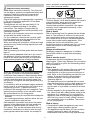
: ,PSRUWDQWVDIHW\LQIRUPDWLRQ
Read these instructions carefully. Only then will
you be able to operate your appliance safely and
correctly. Retain the instruction manual and
installation instructions for future use or for
subsequent owners.
Check the appliance for damage after unpacking
it. Do not connect the appliance if it has been
damaged in transport.
The appliance can only be used safely if it is
correctly installed according to the safety
instructions. The installer is responsible for
ensuring that the appliance works perfectly at its
installation location.
The width of the extractor hood must correspond
at least with the width of the hob.
For the installation, observe the currently valid
building regulations and the regulations of the
local electricity and gas suppliers.
When conveying the exhaust air, official and legal
regulations (e.g. state building regulations) must
be followed.
'DQJHURIGHDWK
Risk of poisoning from flue gases that are drawn
back in.
Always ensure adequate fresh air in the room if
the appliance is being operated in exhaust air
mode at the same time as room air-dependent
heat-producing appliance is being operated.
Room air-dependent heat-producing appliances
(e.g. gas, oil, wood or coal-operated heaters,
continuous flow heaters or water heaters) obtain
combustion air from the room in which they are
installed and discharge the exhaust gases into
the open air through an exhaust gas system (e.g.
a chimney).
In combination with an activated vapour extractor
hood, room air is extracted from the kitchen and
neighbouring rooms - a partial vacuum is
produced if not enough fresh air is supplied. Toxic
gases from the chimney or the extraction shaft
are sucked back into the living space.
■ Adequate incoming air must therefore always be
ensured.
■ An incoming/exhaust air wall box alone will not
ensure compliance with the limit.
Safe operation is possible only when the partial
vacuum in the place where the heat-producing
appliance is installed does not exceed
4Pa
(0.0
4mbar). This can be achieved when the air
needed for combustion is able to enter through
openings that cannot be sealed, for example in
doors, windows, incoming/exhaust air wall boxes
or by other technical means.
In any case, consult your responsible Master
Chimney Sweep. He is able to assess the house's
entire ventilation setup and will suggest the
suitable ventilation measures to you.
Unrestricted operation is possible if the vapour
extractor hood is operated exclusively in the
circulating-air mode.
5LVNRIGHDWK
Risk of poisoning from flue gases that are drawn
back in. The exhaust air must not be conveyed
into a functioning smoke or exhaust gas flue or
into a shaft which is used to ventilate installation
rooms that contain heating appliances. If the
exhaust air is to be conveyed into a non-
functioning smoke or exhaust gas flue, you must
obtain the consent of the heating engineer
responsible.
'DQJHURIVXIIRFDWLRQ
Packaging material is dangerous to children.
Never allow children to play with packaging
material.
5LVNRIHOHFWULFVKRFN
Components inside the appliance may have
sharp edges. These may damage the connecting
cable. Do not kink or pinch the connecting cable
during installation.
5LVNRIILUH
■ Fatty deposits in the grease filter may catch fire.
The specified safety clearances must be
complied with in order to prevent a build-up of
heat. Refer to the information provided for your
cooker. If gas and electric hobs are being
operated together, the largest specified
clearance applies.
The appliance must be installed with no more
than one side directly next to a high-sided unit or
a wall. The clearance between the appliance
and the wall or high-sided unit must be at least
500 mm.
Risk of fire!
■ Grease deposits in the grease filter may catch
fire. Never work with naked flames close to the
appliance (e.g. flambéing). Do not install the
appliance near a heat-producing appliance for
solid fuel (e.g. wood or coal) unless a closed,
non-removable cover is available. There must
be no flying sparks.
5LVNRILQMXU\
■ Components inside the appliance may have
sharp edges. Wear protective gloves.
Risk of injury!
■ The appliance may fall down if it has not been
properly fastened in place. All fastening
components must be fixed firmly and securely.

- 7 -
Risk of injury!
■ Changes to the electrical or mechanical
assembly are dangerous and may lead to
malfunctions. Do not make any changes to the
electrical or mechanical assembly.
*HQHUDOLQIRUPDWLRQ
The surfaces of the appliance are easily damaged. Avoid
damaging them during installation.
([KDXVWDLUPRGH
1RWH
The air must not be discharged into a flue
that is used for exhausting fumes from appliances
burning gas or other fuels (not applicable to
appliances that only discharge the air back into
the room).
■ Before conveying the exhaust air into a non-functioning smoke
or exhaust gas flue, obtain the consent of the heating engineer
responsible.
■ If the exhaust air is conveyed through the outer wall, a telescopic
wall box should be used.
([KDXVWGXFW
1RWH The device manufacturer does not assume any warranty for
complaints attributable to the pipe section.
■ The device achieves its optimum performance by means of a
short, straight exhaust air pipe and as large a pipe diameter as
possible.
■ As a result of long rough exhaust air pipes, many pipe bends or
pipe diameters that are smaller than 150mm, the optimum
extraction performance is not achieved and fan noise is
increased.
■ The pipes or hoses for laying the exhaust air line must consist of
non-combustible material.
5RXQGSLSHV
An inner diameter of 150mm, but at least 120mm, is
recommended.
)ODWGXFWV
The inner cross-section must correspond to the diameter of the
round pipes.
GLDĂPPFDĂFP
GLDĂPPFDĂFP
■ Flat ducts should not have any sharp deflections.
■ Use sealing strips for deviating pipe diameters.
&LUFXODWLQJDLUPRGH
1RWH The appliance must only be operated when it is securely
installed and the pipework is connected.
(OHFWULFDOFRQQHFWLRQ
: 5LVNRIHOHFWULFVKRFN
Components inside the appliance may have sharp edges. These
may damage the connecting cable. Do not kink or pinch the
connecting cable during installation.
The required connection data can be found on the rating plate
inside the appliance; to do this, remove the metal mesh grease
filter.
This appliance complies with the EC interference suppression
regulations.
This appliance may be connected to a correctly installed earthed
socket only.
Attach the earthed socket preferably inside the flue duct.
■ The earthed socket should be connected via its own circuit.
■ If the earthed socket is no longer accessible following installation
of the appliance, a disconnecter must be fitted as for a
permanent connection.
If a permanent connection is required, the
installation must feature an all-pole disconnecter
(circuit breakers, fuses and contactors) with a
min.
3mm contact opening. The permanent
connection may be installed by an electrician
only.
3UHSDULQJIRULQVWDOODWLRQ
&KHFNLQJWKHZDOO
■ The wall must be level, vertical and adequately load-bearing.
■ The depth of the bore holes must be the same length as the
screws. The wall plugs must have a secure grip.
■ The enclosed screws and wall plugs are suitable for solid
brickwork. Suitable fasteners must be used for other structures
(e.g. plasterboard, porous concrete, poroton bricks).
■ The maximum weight of the extractor hood is NJ.
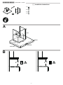
$SSOLDQFHGLPHQVLRQVDQGVDIHW\FOHDUDQFHV
■ Observe the appliance's dimensions. )LJ $
■ Comply with the safety clearances. )LJ %
If the installation instructions for the gas cooking appliance specify
a different distance, the larger of the two must always be provided
for.
3UHSDULQJWKHZDOO
&DXWLRQ
Ensure that there are no electric wires, gas or water pipes in the
area where holes are to be made.
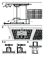
Mark a vertical centre line on the wall from the ceiling to the lower
edge of the extractor hood. )LJ
Mark holes for the angle brackets in the flue. The centre of the
angle brackets is marked with a notch. Centre the angle brackets
using the centre line, position them horizontally and mark the
positions of the holes.
Drill the holes.
Press in the wall plugs flush with the wall.
)LWWLQJWKHZDOOEUDFNHW
Screw on the fixing bracket for the flue duct. )LJ
3UHSDULQJWKHDSSOLDQFH
Remove the metal grease filter. )LJ
,QVWDOOLQJWKHDSSOLDQFH
$WWDFKLQJDQGDOLJQLQJWKHDSSOLDQFH
: 5LVNRILQMXU\
Components inside the appliance may have sharp edges. Wear
protective gloves.
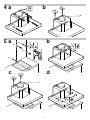
First remove the protective foil from the back of the appliance
and, following installation, remove the foil completely.
Align the appliance horizontally. )LJ D
Mark the holes. )LJ D
Tighten the screws V. )LJ E
Drill the holes. )LJ D
Press in the wall plugs flush with the wall.
Screw on mounting brackets for the appliance.
Fit the appliance.
Align the appliance horizontally by turning the screws on the
mounting brackets. The screws are accessible from the inside of
the appliance. )LJ E
Tighten the screws. )LJ E
Loosen the screws V to adjust the appliance in height. )LJ F
Tighten the screws. )LJ G
Install the metal grease filters.
&RQQHFWLQJWKHDSSOLDQFH
&RQQHFWLQJ WKH DLU H[WUDFWRU DQG HVWDEOLVKLQJ D FRQQHFWLRQ WR
WKHPDLQV
1RWHV
■ For exhaust-air operation, a backflow flap should be fitted. If a
backflow flap has not been included with the appliance, it can be
obtained from a specialist retailer.
■ If the exhaust air is conveyed through the outer wall, a telescopic
wall box should be used.
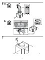
&RQQHFWLQJWKHH[KDXVWDLUSLSH
1RWH If an aluminium pipe is being used, smooth the connection
area beforehand.
Attach the exhaust air pipe directly to the air pipe connector.
)LJ D
Connect it to the exhaust air opening.
Use suitable means to seal the joints.

- 8 -
&RQQHFWLQJWKHSRZHUVXSSO\
Plug the mains plug into the earthed socket. )LJ
If a fixed connection is required, follow the instructions in the
Electrical connection section.
,QVWDOOLQJWKHDFWLYHFDUERQILOWHURQO\LQ
FLUFXODWLQJDLUPRGH)LJE
Remove the metal grease filters.
Insert the new active carbon filter and secure it in place using the
fastening hooks.
Fix the back flap on the exhaust and secure with clamping ring.
Mount the metal grease filters.
$WWDFKLQJWKHIOXHGXFW
: 5LVNRILQMXU\
Components inside the appliance may have sharp edges. Wear
protective gloves.
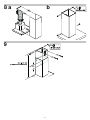
Remove the pieces of protective film from the flue duct.
Place the flue duct on the appliance and fix it in place. Gently
push the two side panels apart, hook them in behind the angle
bracket and then push them back together as far as they will go
(i.e. until they are touching the ends of the bracket). )LJ D
Screw the flue duct to the ends of the angle bracket. )LJ E
,QVWDOOLQJWKHIOXHGXFWH[WHQVLRQ)LJ
: 5LVNRILQMXU\
Components inside the appliance may have sharp edges. Wear
protective gloves.
Remove the pieces of protective film from the flue duct extension.
Place the flue duct extension inside the flue duct. Gently push
downward till touches the chimney body.
Fix the bottom angle bracket to the wall as shown in above figure.
Fix the top angle bracket as per the required height of flue duct
extension as shown in above figure.
1RWH The minimum overlap between flue duct and flue duct
extension must be 100 mm.
Screw the flue duct extension to the ends of the angle bracket.
5HPRYLQJWKHDSSOLDQFH
Disconnect the appliance from the power supply.
Remove the flue duct.
Loosen the exhaust air lines.
Remove the metal grease filter.
Unscrew in the screws for the appliance bracket slightly; do not
loosen them fully.
Remove the appliance.
Remove the angle bracket for the flue duct.
BSH Household Appliances Manufacturing Pvt. Ltd.
Arena House, 2nd Floor Main Building
Plot No.103, Road No.12
MIDC, Andheri East,
Mumbai-400093
www.bosch-home.com
-
 1
1
-
 2
2
-
 3
3
-
 4
4
-
 5
5
-
 6
6
-
 7
7
-
 8
8


Bosch DWB068D50I/01 Installation guide
- Category
- Cooker hoods
- Type
- Installation guide
- This manual is also suitable for
Ask a question and I''ll find the answer in the document
Finding information in a document is now easier with AI
Related papers
-
Bosch Ceiling hood User manual
-
Bosch PKM845F11E Installation guide
-
-
Bosch DDA097G59/03 User manual
-
Bosch DWB127E51/01 User manual
-
-
-
Bosch washing machine Operating instructions
-
-
Bosch HSB738354A Installation guide
Other documents
-
Siemens LC98KA570B/01 User manual
-
Neff T58TS6BN0 Installation guide
-
 Cafe CVM1790SSSS Installation guide
-
GE PSA1201RSS Installation guide
-
Ingersoll-Rand A801X080CM5SAB Installer's Manual
-
Hearth and Home Technologies Ventilation Hood HRV200PLUS User manual
-
GE DCVH680GJWW Installation guide
-
GE PVM9005FMDS Installation guide
-
-
State Water Heaters BTP(V)-540A User manual
