Tripp Lite 0SU52015 Installation guide
- Category
- KVM switches
- Type
- Installation guide

International HQ
Jerusalem, Israel
Tel: + 972 2 535 9666
minicom@minicom.com
North American HQ
Linden
,
New Jersey
Tel: + 1 908 4862100
European
HQ
Dübendorf, Switzerland
Tel: + 41 1 823 8000
info.europe@minicom.com
Italy
Rome
Tel: + 39 06 8209 7902
info.italy@minicom.com
www.minicom.com Customer support - support@minicom.com
V1.7 7/04
Phantom Operating Guide

Introduction
1-1
Chapter 1: Introduction
The Phantom system from Minicom is a CAT5 based Distributed KVM Switching system for server
management. Connect up to 64 computers in the Phantom system. The system can be managed and controlled by
1 or 2 users. For 2-user control see the MX II Guide.
The Phantom system components
The Phantom system consists of:
• Management unit
• Remote units
• Cables and accessories – explained in the Installation guide
• Marketing & Documentation CD – includes application software
Manager unit
The Management unit can be either a Universal Phantom Manager (UPM) external box or an internal PCI card
Remote units
The Remote units may be either internal PCI cards or Micro-sized external boxes called Specters.
There are a number of Specter types as follows:
• For PS/2 interface computers – Specter PS/2 for 1-User system. Specter II PS/2 for a 2-User system
• For SUN computers – Specter SUN for 1 or 2-User systems
• For RS232 controllable devices – Specter RS232 for 1 or 2-User systems
• For computers with USB interfaces– Specter USB for 1 or 2-User systems
All Management and Remote models are fully compatible with each other.
Compatibility
The Phantom system is compatible with:
• IBM compatible, Silicon Graphics, SUN and Alpha computers
• VGA, SVGA, or XGA video standards
• All major computer and server manufacturers
• IntelliMouse™, Logitech WheelMouse, and PS/2 mice
• Microsoft DOS, Windows 3.1, 95, 98, 2000, NT4, ME, and XP. Novel, Linux, SGI, BeOS, HP UX Alpha UNIX, Open
VMS
• PS/2, SUN, RS232, USB interfaces

The Phantom configuration
1-2
Features
The Phantom system gives you:
• Control and monitor mixed, multi-platform server environments of up to 63 remote computers from 1 or 2 Manager
position
• Advanced On Screen Display management (including multi-layer security), and BIOS level access
• The option to connect a keyboard, video and mouse to any Remote PCI card computer – referred to as a Local
Workstation
• A total distance of up to 110m/360ft between the Manager computer and the last connected Remote computer
• Pure hardware solution. No drivers. No IRQs. No interrupts
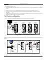
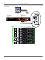
The Phantom configuration
Figure 1-1 illustrates the Phantom configuration for the Manager and Remote PCI cards.
SD
P1610
Remote
Computer 1
OUT
IN
OUT
IN
OUT
IN
OUT
RS232
CAT5 System Cable CAT5 System Cable CAT5 System Cable
Terminator in the
last Phantom Unit
Manager
Computer
Remote
Computer 2
Remote
Computer 3
Manager
Card
Remote
Card
Remote
Card
Remote
Card
Figure 1-1 The card version configuration
Figure 1-2 illustrates the Phantom configuration for the UPM (without the optional computer) and Specter
models.
Link
Active
Link
Active
Link
Active
CAT5 System Cable CAT5 System Cable
Remote
Computer 1
Remote
Computer 2
Remote
Computer 3
Terminator
in the last
Phantom Unit
Specter Specter Specter
UPM
www.minicom.com
USER COMPUTER
SYSTEM SER VICEPOWER
85-265VAC 50/60 Hz
CAT5 System Cable
SD
P50
Figure 1-2 The Phantom Specter configuration with the UPM

Introduction
1-3
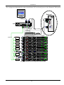
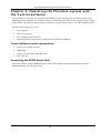
The configuration diagram below shows both Remote PCI cards and Specters in the Phantom UPM system.
CAT5 cable
ProLiant DL3 60
9.1 - G B
10k
ULTRA2 SCSI
9.1 - G B
10k
ULTRA2 SCSI
ProLiant DL3 60
9.1 - G B
10k
ULTRA2 SCSI
9.1 - G B
10k
ULTRA2 SCSI
ProLiant DL3 60
9.1 - G B
10k
ULTRA2 SCSI
9.1 - G B
10k
ULTRA2 SCSI
ProLiant DL3 60
9.1 - G B
10k
ULTRA2 SCSI
9.1 - G B
10k
ULTRA2 SCSI
ProLiant DL3 60
9.1 - G B
10k
ULTRA2 SCSI
9.1 - G B
10k
ULTRA2 SCSI
Pro Lian t DL3 60
9.1 - GB
10k
ULTRA2 SCSI
9.1 - GB
10k
ULTRA2 SCSI
www.minicom.com
USER COMPUTER
SYSTEM SERVICEPOWER
85-265VAC 50/60 Hz
Link
Active
MINICOM
www.mi nicom .com
PHANTOM
Specter
Link
Active
MINICOM
www.mi nicom .com
PHANTOM
Specter
Link
Active
MINICOM
www.mi nicom .com
PHANTOM
Specter
Link
Active
MINICOM
www.mi nicom .com
PHANTOM
Specter
Link
Active
MINICOM
www.mi nicom .com
PHANTOM
Specter
3in1Cable
SD
P110
RS232 Serial Cable
Optional
ProLiant DL3 60
9.1 - G B
10k
ULTRA2 SCSI
9.1 - G B
10k
ULTRA2 SCSI
ProLiant DL36 0
9.1 - G B
10k
ULTRA2 SCSI
9.1 - G B
10k
ULTRA2 SCSI
ProLiant DL3 60
9.1 - G B
10k
ULTRA2 SCSI
9.1 - G B
10k
ULTRA2 SCSI
Link
Active
MINICOM
www.minicom.com
PHANTOM
Specter
Link
Active
MINICOM
www.minicom.com
PHANTOM
Specter
OUT
IN
OUT
IN
UPM
Figure
1-3 Phantom mixed configuration with the UPM

The Phantom configuration
1-4
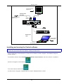
The configuration diagram below shows both Remote PCI cards and Specters in the Phantom RackManager
UPM system.
ProLiant DL360
9.1 - G B
10k
ULTRA2 SCSI
9.1 - GB
10k
ULTRA2 SCSI
ProLiant DL360
9.1 - G B
10k
ULTRA2 SCSI
9.1 - GB
10k
ULTRA2 SCSI
ProLiant DL360
9.1 - G B
10k
ULTRA2 SCSI
9.1 - GB
10k
ULTRA2 SCSI
ProLiant DL360
9.1 - G B
10k
ULTRA2 SCSI
9.1 - GB
10k
ULTRA2 SCSI
ProLiant DL360
9.1 - G B
10k
ULTRA2 SCSI
9.1 - GB
10k
ULTRA2 SCSI
ProLiant D L360
9.1 - G B
10k
ULTRA2 SCSI
9.1 - GB
10k
ULTRA2 SCSI
Link
Active
MINICOM
www. min ic om. co m
PHANTOM
Specter
Link
Active
MINICOM
www. min ic om. co m
PHANTOM
Specter
Link
Active
MINICOM
www. min ic om. co m
PHANTOM
Specter
Link
Active
MINICOM
www. min ic om. co m
PHANTOM
Specter
Link
Active
MINICOM
www. min ic om. co m
PHANTOM
Specter
SD
P110
Optional
ProLia nt DL360
9.1 - GB
10k
ULTRA2 SCSI
9.1 - GB
10k
ULTRA2 SCSI
ProLiant DL360
9.1 - G B
10k
ULTRA2 SCSI
9.1 - GB
10k
ULTRA2 SCSI
ProLia nt DL360
9.1 - GB
10k
ULTRA2 SCSI
9.1 - GB
10k
ULTRA2 SCSI
Link
Active
MINICOM
www.minicom.com
PHANTOM
Specter
Link
Active
MINICOM
www.minicom.com
PHANTOM
Specter
OUT
IN
OUT
IN
85-265VAC 50/60 Hz
Phantom
Universal Manager
www.mi nicom.c om
MINICOM
SERVICE SYSTEM
COMPUTER
RackManager
Front panel
3 in 1 CPU cable
RS232 Serial cable
CAT5 cable
Figure
1-4 Phantom mixed configuration with the RackManager UPM

OSD Technology
1-5
OSD Technology
The Phantom system superimposes a menu on the Manager position computer screen. This On-Screen-Display
(OSD) consists of three sections. From the OSD, you activate various functions discussed in the Operating guide.
The Local Workstation Option
When using the Phantom Remote PCI cards, you have the option of working at the remote computer by
connecting a keyboard, video, and mouse to it. This is called the Local Workstation option.
The Phantom Manager and the local user can both work on the remote computer with a one second Access-
Timeout. This means that when one of them stops working for one second the other can take control.
Note! This option is not available with the Phantom Specter.

The OSD functions
2-1
Chapter 2: The OSD functions
The Phantom system is controlled and monitored through an On-Screen-Display (OSD) on the Manager screen.
When the Phantom Manager is the UPM you can also use Minicom’s Control software or equivalent software.
The Control software is discussed in chapter 4. The OSD contains a number of different windows that are
accessed using Hot-keys. Each window has its own special function.
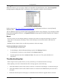
Displaying the OSD
To display the OSD:
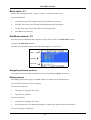
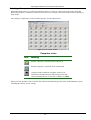
Press Shift, Shift. The Select Computer window appears. See Figure 2-1.
Pressing keyboard hotkeys
Note! For all keyboard hotkey sequences mentioned in this guide – press the first key, release and then
press the next key.
Note! When using a UPM not connected to a local computer the OSD appears automatically.
Instructions
and
Hot-keys
Computers
Name
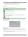
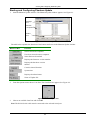
Figure 2-1 The Select Computer window
The OSD is divided into three sections. These are:
• Name
• Computers
• Instructions and Hot-key guide
The Computers section
The Computers section displays the computers in groups of eight.
Navigate between the groups with the Page Up and Page Down Arrow keys.
In this section you select computers - discussed below.
Line Color codes
Each computer line can be one of three colors as follows:
Yellow Connected and switched on computer.
Black Connected and switched on computer with a Local Workstation attached and presently being
used locally. After remaining idle for 30 seconds, it changes to yellow.
Blue Unconnected or switched off computer.

The hotkey functions
2-2
Selecting a Computer
To select a computer:
1. Navigate to the desired computer with the Up and Down Arrow keys.
Or
Type the computer number. It will appear in the “SELECT COMPUTER” line. See Figure 2-1.
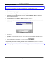
2. Press Enter. The selected computer’s screen replaces the Manager’s screen. A Confirmation label appears
showing which computer is accessed. See Figure 2-2. Control and monitor the computer from the Manager
KVM position.
Figure 2-2 The Confirmation label
To return to the OSD:
Press Shift, Shift.
To return to the Manager computer screen:
Press Shift, Esc.
To return to the previously accessed computer screen:
Press Shift, Tab.
The hotkey functions
The OSD hotkey functions are briefly outlined in the table below.
Hotkey Function
F1 Move label identifying the current selected computer to anywhere on the screen
F2 Opens Edit window to edit text – change computer names etc.
F3 Opens Setup window to set parameters – scan times etc.
F4 Activate scan
F5 Image tuning
F6 Autoskip – during a scan skip inactive computers
F7 Opens Password window to activate password protection – explained in chapter 3
F8 Keyboard language
F9 Change the display hotkey
F10 Firmware upgrade/ Numbering software access mode – explained in chapters 5&6
F11 Load defaults – explained in chapter 4
F12 Auto-numbering – explained in chapter 3

The OSD functions
2-3
Move Label - F1
Position the Confirmation label – Figure 2-2 above – anywhere on the screen.
To position the label:
1. Navigate to the desired computer using the Up and Down arrow keys.
2. Press F1. The selected screen image and Identification label will appear.
3. Use the arrow keys to move the label to the desired position.
4. Press Esc to save and exit.
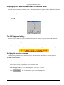
Edit Mode window - F2
You can edit text in the Name and Computers sections. This is done in the Edit Mode window.
To display the Edit Mode window:
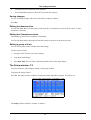
Press F2. The Edit Mode window with instructions appears, see Figure 2-3.
Instructions
Computers
Name
Figure 2-3 The Edit Mode window
Navigating between sections
To navigate between the Name and Station sections, use the Up and Down Arrow keys.
Editing options
The editing options below apply to all OSD windows in which you can edit characters.
You can either overwrite or erase a character.
To overwrite a character:
1. Navigate to it using the Arrow keys.
2. Type the new character.
To erase a character:
1. Navigate to it using the Arrow keys.
2. Press the Spacebar. The character disappears. A blank space replaces the erased character.
To erase a sequence of characters:

The hotkey functions
2-4
1. Navigate to the first character in the sequence.
2. Press and hold the Spacebar down until you erase the sequence.
Saving changes
To save all editing changes and return to the Select Computer window:
Press Esc.
Editing the Name section
You can substitute the text in the Name section with up to 30 characters in each of the two lines. A space
constitutes a character.
Editing the Computers section
The numbering at the start of each line is unalterable.
You can substitute the text that appears after the number with up to 20 characters per line.
Editing a group of lines
You can edit a group of lines with the same data change.
To edit a group of lines:
1. Navigate to the first line you want to change.
2. Type the desired change.
3. Press End, End. The rest of the column downwards takes on the same change.
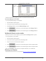
The Setup window - F3
You set parameters, and configure settings, in the Setup window.
To display the Setup window:
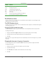
Press F3. The Setup window with the relevant instructions and hotkeys appears. See Figure 2-4.
Figure 2-4 The Setup window
The Setup window contains 7 columns, as follows:

The OSD functions
2-5
Column Function
Numbers Computer numbers in groups of 8
SCN Scanning time period
DSP Confirmation label display time
KB Keyboard setting, either PS or Unix
MS Mouse type
OUT Security Timeout period (Explained in chapter 3)
1-6 Security profiles (Explained in chapter 3)
The SCN (Scan) column
The SCN column shows the length of time in seconds that a remote computer’s screen will appear on the
Management screen during scanning.
The DSP (Display) column
The DSP column shows the length of time in seconds that the remote computer’s Confirmation label appears
on the Management screen.
Changing the SCN and DSP time spans
The SCN and DSP time spans are preset to 030 seconds. You can adjust these times to suit your needs.
To change the time span:
1. Navigate with the Tab or Right and Left Arrow keys to the time span you want to change.
2. Type the desired time span using the numbers above the keyboard letters.
3. Press Esc.
When typing over a group of three digits, the cursor automatically reverts to the first digit once you edit the
third digit.
Changing the time span of a group of computers
You can change the time spans of the SCN and DSP columns from a particular computer downwards.
To change the time span:
1. Navigate to the time span of the first computer you wish to change.
2. Type the desired change.
3. Press End, End. The remainder of the column takes on the same change.
4. Press Esc.

The hotkey functions
2-6
Removing a computer from the scanning sequence
To remove a computer from the scanning sequence:
1. Type 000 in the SCN column.
2. Press Esc.
Constantly displaying the Confirmation label
To constantly display the computer Confirmation label:
1. Type 999 in the DSP column.
2. Press Esc.
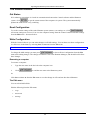
The KB column
The KB column shows the keyboard mapping settings. Set the KB mapping for each computer according to its
operating system.
The default KB mode is PS, which is the standard keyboard mapping for Windows and Linux based operating
systems.
For a UNIX operating system using a standard PS/2 keyboard, set the KB mapping as follows:
• U1 for HP UNIX and SGI
• U2 for Alpha UNIX and Open VMS
To change the KB column from PS to U1 or U2:
1. Navigate to the KB field by using the Tab or Arrow keys.
2. Press the Spacebar. The display interchanges between PS, U1 and U2. Find the desired setting.
3. Press Esc.
The MS column
The Phantom system automatically detects the mouse types, and configures the system accordingly.

The OSD functions
2-7
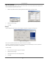
Scanning Computers – F4
You scan computers from the Select Computer window.
To start scanning:
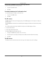
Press F4. During scanning a Confirmation label appears, showing which Remote computer is presently
displayed. See Figure
2-5.
Figure 2-5 The Scan Confirmation label
Note! The scan will skip any active computer set to 000 in the SCN column.
To stop scanning press F4.
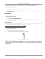
Image tuning - F5
You can tune the image of any remote computer screen from the Select Computer window.
To adjust the screen image:
1. Navigate to the remote computer you wish to adjust.
2. Press F5. The screen image of the selected computer appears, together with the Image Tuning label. See
Figure
2-6.
Figure 2-6 The Image Tuning label
3. Adjust the image by using the Right and Left Arrow keys.
4. When the image is satisfactory, press Esc.
Note! Picture quality is relative to distance. The further away a remote computer is from the Manager position,
the lower the image quality, and the more tuning needed. So place the higher resolution computers closer to the
manager unit.

The OSD functions
2-8
Skipping out unconnected or switched off computers- F6
When navigating through the list of computers, you can skip out the unconnected or switched off computers.
You do this with Autoskip. By default, Autoskip is activated.
To activate or deactivate Autoskip:
In the Setup window (F3), press F6. The F6 Autoskip in the hotkey section of the OSD changes from ON to
OFF
When Autoskip is inactive and the computer being scanned is switched off, then the Manager screen appears
dark.
Changing the keyboard language - F8
You can change the keyboard language from US English (QWERTY)
US
to German (QWERTZ)
DE
or
French (AZERTI) FR.
To change the Language:
1. In the Setup window (F3), press F8 until you reach the desired language.
2. Press Esc.
Changing the OSD display hotkey – F9
The default hotkey to display the OSD, is Shift, Shift. You can replace this hotkey with any of the following:
For the Manager PCI card:
•
Ctrl, Ctrl
•
Ctrl, F11
•
Ctrl, F12
For the UPM:
•
Ctrl, Ctrl
•
Ctrl, F11
•
Print Screen
With a choice of 4 different hotkeys, you can operate up to 4 OSDs from 1 KVM position. Each OSD needs a
different display hotkey. This is useful for cascading systems of for example, the Supervisor MU, Supervisor
Pro, and Phantom.
To change the hotkey:
1. In the Setup window (F3), press F9. The hotkey changes from Shift, Shift to Ctrl, Ctrl. Continue pressing
until you reach the required hotkey.
2. Press Esc. The new hotkey is set. From now on, use the new hotkey to display the OSD.
Exiting the OSD
When the OSD is displayed press Esc to exit the OSD and remain switched to the current computer.

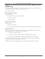
Password protecting the OSD & Auto numbering
3-1
Chapter 3: Password protecting the OSD & Auto
numbering
The Management OSD comes with an advanced password security system that contains 3 different security
levels. Each security level has different access rights to the system.
These levels are as follows:
Administrator (Status A) - Highest
The Administrator can:
• Set and modify all Passwords and security profiles
• Fully access any computer
• Use all OSD functions
Supervisor (Status S) - Middle
The Supervisor can:
• Fully access any computer
• Access the following OSD functions only – F1 Moving the Confirmation label. F4 Scan and F5 Tune.
User (Status U) – Lowest
There are 6 different Users in the Phantom system. Each User has a Profile that defines the access level to
different computers. There are 3 different access levels. These are:
• Y – Full access to a particular computer
• V –Viewing access only, to a particular computer (No keyboard/mouse functionality)
• N – No access to a particular computer – A TIMEOUT label appears if access is attempted
The Administrator defines the desired access levels of each User Profile. This is done in the OSD Setup
window. By default the User Profile settings are full access.
NOTE: There can only be 1 Administrator password, 1 Supervisor password, and 6 User passwords.

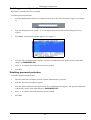
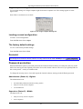
Enabling password protection
3-2
Enabling password protection
By default, password protection is disabled.
To enable password protection:
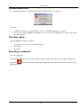
1. From the Management OSD Select Computer window press F7. The Password box appears. See Figure
3-1.
Figure 3-1 The Enter Password box
2. Type the default password “admin”. (You can change this password when customizing the security
system).
3. Press Enter. The Password window appears. See Figure 3-2.
Figure 3-2 The Password window
4. Press F7. The Confirmation label appears. The password indication in the hotkey section of the OSD
changes to PASSWORD ON.
5. Press ‘Y’ to confirm. Password protection is now enabled.
6. Press Esc.
Disabling password protection
To disable the password protection:
1. Enter the OSD Select Computer window with the Administrator’s password.
2. Press F7. The Password window appears.
3. Press F7 again to disable Password protection. The Confirmation label appears. The password indication
in the hotkey section of the OSD changes to PASSWORD OFF.
4. Press ‘Y’ to confirm. Password protection is now disabled.
5. Press Esc.

Password protecting the OSD & Auto numbering
3-3
Setting up a password
The Administrator sets up passwords for each User Profile in the Password window. See Figure 3-3. He can
also edit the names to give each Profile a more identifiable name.
Figure 3-3 The Password window
To set up a password:
1. From the OSD Select Computer window press F7. The Enter Password box appears.
2. Type the Administrator’s password.
3. Press Enter. The Password window appears. See Figure 3-3. The first row marked A is for the
Administrator name and password and the second row marked S is for the Supervisor name and password.
Note! Password characters are not case sensitive, and a space can be a password character. A space will appear
as an asterix.
To set up a password:
1. Navigate to the desired line number.
2. Type:
(i). Identifiable name in the Name column.
(ii). Password in the Password column – between 1 and 8 characters.
3. Press Esc.
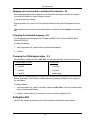
Changing a password
The Administrator can change any name or password from the Password window.
To change a name or password:
1. Navigate to the desired line number.
2. Delete the text by pressing Delete.
3. Type the desired change.
4. Press Esc.
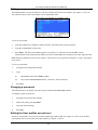
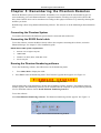
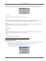
Setting the User profiles access level
Set the 6 User profiles access levels from the OSD Setup window (F3). See Figure 3-4. The 6 User Profiles
correspond to the 6 Users in the Password window see Figure 3-3 above.

Accessing the OSD using a password
3-4
The 6
User
Profiles
Figure 3-4 The Setup window
To set the User Profiles access levels:
1. Navigate to the desired User Profile and computer.
2. Change the desired access level by pressing the Spacebar.
3. Repeat steps 1 and 2 for each User Profile and computer.
4. Press Esc to save the changes. When a User accesses the system with their password they see the access
levels for each computer displayed on the OSD. See Figure 3-5.
Figure 3-5 User access levels
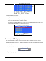
Accessing the OSD using a password
Once password protection is enabled, you can only access the OSD by entering the appropriate password.
The default Administrator’s password is “ADMIN”. The passwords of the other two security statuses are set by
the Administrator.
To access the OSD:
1. Press Shift, Shift. The Enter Password box appears. See Figure 3-6.
Figure 3-6 The Enter Password box
2. Type in the appropriate password.
3. Press Enter.

Password protecting the OSD & Auto numbering
3-5
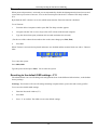
Timeout
When password protection is activated you can automatically disable the Management keyboard, mouse and
screen after a preset time of non-use. You set the Timeout period in the OUT column of the Setup window
(F3).
By default the OUT column is set to 999, which means that the Time Out function is disabled.
To set Timeout:
1. From the Select Computer window press F3. The Setup window appears.
2. Navigate with the Tab or Arrow keys to the OUT column of the desired computer.
3. Type the desired time span (minimum 030 seconds maximum 998 seconds).
( For the rest of the column downwards to take on the same change press End, End.)
4. Press Esc.
When Timeout is activates the keyboard and mouse are disabled and the monitor blacks out with a ‘Timeout’
label.
Figure
3-7 The TIMEOUT label
To re-enter the system:
Press Shift, Shift.
Type the password and press Enter. You re-enter the system.
Reverting to the default OSD settings - F11
The Administrator can reset all editing and configurations done in the different OSD windows, to the default
factory settings.
Warning! This feature will erase all settings including computer names, passwords and security profiles.
To revert to the default OSD settings:
1. Enter the Password window (F7).
2. Press F11.
3. Press ‘Y’ to confirm. The OSD reverts to the default settings.

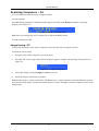
Auto numbering – F12
3-6
Auto numbering – F12
Auto numbering gives each Phantom Remote a sequential ID number. Auto numbering is done through the
Management OSD.
For Auto numbering to work properly ALL connected computers MUST be switched on
To perform Auto numbering:
1. From the OSD Select computer window Press F7. The Enter Password box appears. See Figure
3-8.
Figure
3-8 The Enter Password box
2. Type the Administrators password (default password is ADMIN) and press Enter. The Password
window appears.
Figure
3-9 The Password window
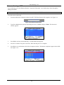
3. Press F12 to activate Auto numbering. A Confirmation label appears.
4. Press Y to confirm. The process activates. Wait until the process is complete.
5. Press Esc to save and return to the Select Computer window. The Remote computers appear on the OSD.
See Figure
3-10.
Figure
3-10
Page is loading ...
Page is loading ...
Page is loading ...
Page is loading ...
Page is loading ...
Page is loading ...
Page is loading ...
Page is loading ...
Page is loading ...
Page is loading ...
Page is loading ...
Page is loading ...
Page is loading ...
Page is loading ...
Page is loading ...
Page is loading ...
Page is loading ...
Page is loading ...
Page is loading ...
Page is loading ...
Page is loading ...
-
 1
1
-
 2
2
-
 3
3
-
 4
4
-
 5
5
-
 6
6
-
 7
7
-
 8
8
-
 9
9
-
 10
10
-
 11
11
-
 12
12
-
 13
13
-
 14
14
-
 15
15
-
 16
16
-
 17
17
-
 18
18
-
 19
19
-
 20
20
-
 21
21
-
 22
22
-
 23
23
-
 24
24
-
 25
25
-
 26
26
-
 27
27
-
 28
28
-
 29
29
-
 30
30
-
 31
31
-
 32
32
-
 33
33
-
 34
34
-
 35
35
-
 36
36
-
 37
37
-
 38
38
-
 39
39
-
 40
40
-
 41
41


Tripp Lite 0SU52015 Installation guide
- Category
- KVM switches
- Type
- Installation guide
Ask a question and I''ll find the answer in the document
Finding information in a document is now easier with AI
Related papers
-
Tripp Lite 0SU52016 Owner's manual
-
Tripp Lite CAT5 Smart KVM Extender User manual
-
-
-
Tripp Lite 0SU51068 User manual
-
-
-
Tripp Lite Minicom Specter II PS/2 8 Pack Installation guide
-
-
Tripp Lite 5UM7017 User manual
Other documents
-
Minicom Advanced Systems Switch 5UM20094 User manual
-
Sensata CRX3108 CRXS Firmware Upgarde Operating instructions
-
-
-
Remote Pro RPR100-C-002 Installation guide
-
ConnectPRO MIT-CAT5 8 User manual
-
-
-
Ultratec Minicom IV User manual
-