Page is loading ...

Essence®
INSTALLATION
GUIDE
For help, call 1-877-BIG-FANS
or visit www.bigassfans.com

ESSENCE®
WWW.BIGASSFANS.COM ©2013 DELTA T CORP. ALL RIGHTS RESERVED
Installation Checklist
Did a structural engineer approve the mounting structure? See page 7 for Big Ass Fans-approved
mounting structures.
Are you familiar with the function and use of the safety cable? See pages 21–22 for information on
properly securing the safety cable.
Will the fan be installed so that the airfoils are at least 10 ft (3.05 m) above the oor?
Will the fan be installed so that the airfoils have at least 2 ft (0.61 m) of clearance from
obstructions?
Will the fan be installed so that it is not subjected to high winds such as from a Heating,
Ventilating, and Air Conditioning (HVAC) system or near a large garage door? If the fan is
mounted at the same level or higher than a diffuser, the winglets or airfoil tips must be at a distance
that is at least 1x the measure of the fan’s diameter. If the fan is mounted at the same height or below
a diffuser, the winglets or airfoil tips must be at a distance that is at least 2x the measure of the fan’s
diameter.
Will the distance between multiple fans be at least 2.5x the fans’ diameter when measured from
the centers of the fans?
If you ordered multiple fans, did you keep the parts of each fan together?
Customer Service: 1-877-BIG-FANS
(International: +1 859 233 1271)

i
ESSENCE®
WWW.BIGASSFANS.COM ©2013 DELTA T CORP. ALL RIGHTS RESERVED
Installation Guide:
Apr. 2015
Rev. F
This product was manufactured in a plant whose
Management System is certied as being in
conformity with ISO 9001:2008.
Installation Guide
Essence®
Essence and the Essence logo are trademarks of Delta T Corporation. All other trademarks used herein are the properties of their respective owners. No part of this document may be reproduced or
translated into a different language without the prior written consent of Big Ass Fan Company. The information contained in this document is subject to change without notice. For the most up-to-date
information, see the online Essence Installation Guide at www.bigassfans.com.
www.bigasssolutions.com/patents
Contact Information
Manufacturing
2425 Merchant Street
Lexington, KY 40511
1-877-BIG-FANS
www.bigassfans.com
Customer Service
2348 Innovation Drive
Lexington, KY 40511
1-877-BIG-FANS
Intl.: +1 859 233 1271
www.bigassfans.com
Warranty Returns
800 Winchester Road
Lexington, KY 40505
1-877-BIG-FANS
www.bigassfans.com
Australia Ofce
Unit 22, 1029 Manly Road
Tingalpa QLD 4173, Australia
(07) 3292 0100
www.bigassfans.com/au
Conforms to ANSI/UL STD 507–Electric Fans
Conforms to CSA C22.2 No.113–Fans & Ventilators

ESSENCE®
WWW.BIGASSFANS.COM ©2013 DELTA T CORP. ALL RIGHTS RESERVED
ii
IMPORTANT SAFETY INSTRUCTIONS
READ AND SAVE THESE INSTRUCTIONS
TO REDUCE THE RISK OF FIRE, ELECTRIC SHOCK, OR INJURY TO PERSONS, OBSERVE THE FOLLOWING:
CAUTION: Installation work and electrical wiring must be done by qualied person(s) in accordance with all applicable codes and
standards.
CAUTION: When cutting or drilling into wall or ceiling, do not damage electrical wiring and other hidden utilities.
CAUTION: Use this unit only in the manner intended by the manufacturer. If you have questions, contact the manufacturer.
WARNING: Before servicing or cleaning unit, switch power off at service panel and lock the service disconnecting means to prevent
power from being switched on accidentally. When the service disconnecting means cannot be locked, securely fasten a prominent
warning device, such as a tag, to the service panel.
CAUTION: The installation of a Big Ass Fan must be in accordance with the requirements specied in this installation manual
and with any additional requirements set forth by the National Electric Code (NEC), ANSI/NFPA 70-2011, and all local codes. Code
compliance is ultimately YOUR responsibility! Failure to comply with these codes could result in personal injury or property damage.
CAUTION: Exercise caution and common sense when powering the fan. Do not connect the fan to a damaged or hazardous power
source. Do not attempt to resolve electrical malfunctions or failures on your own. Contact Big Ass Fans if you have any questions
regarding the electrical installation of this fan.
WARNING: To reduce the risk of re, electric shock, and injury to persons, Big Ass Fans must be installed with Big Ass Fan supplied
controllers that are marked (on their cartons) to indicate the suitability with this model. Other parts cannot be substituted.
WARNING: The only solid state control approved for use with this fan is Big Ass Fans control model 003820. Do not use any other
solid state control with this fan.
CAUTION: When service or replacement of a component in the fan requires the removal or disconnection of a safety device, the
safety device is to be reinstalled or remounted as previously installed.
WARNING: Risk of re, electric shock, or injury to persons during cleaning and user-maintenance! Disconnect the fan from the power
supply before servicing.
CAUTION: Do not bend the airfoils when installing, adjusting, or cleaning the fan. Do not insert foreign objects in between rotating
airfoils.
WARNING: Stay alert, watch what you are doing, and use common sense when installing fans. Do not install fans if tired or under the
inuence of drugs, alcohol, or medication. A moment of inattention while installing fans may result in serious personal injury.
CAUTION: The installation of this fan requires the use of some power tools. Follow the safety procedures found in the owner’s
manual for each of these tools and do not use them for purposes other than those intended by the manufacturer.
CAUTION: The Big Ass Fans product warranty will not cover equipment damage or failure caused by improper installation.
CAUTION: Suitable for use in wet locations when installed in a GFCI protected branch circuit.
WARNING: This appliance is not intended for use by persons (including children) with reduced physical, sensory or mental
capabilities, or lack of experience and knowledge, unless they have been given supervision or instruction concerning use of
the appliance by a responsible person. Children should be supervised to ensure that they do not play with the appliance.
ATTENTION: If installing the fan in the United States, the fan must be installed per the following National Fire Protection Association
(NFPA) guidelines:
• The fan must be centered approximately between four adjacent sprinklers.
• The vertical distance from the fan to the sprinkler deector must be at least 3 ft (91.4 cm).
• The fan must be interlocked to shut down immediately upon receiving a waterow signal from the alarm system.
Leave this installation guide with the owner of the fan after installation is complete.

Reference Guide
The following is intended as a reference guide. See the referenced pages for complete fan installation and operating instructions.
Mounting the fan
If mounting to bar joists, see Mounting Structure:
Bar Joists on page 8.
If mounting to a wood frame structure, see
Mounting Structure: Wood Frame on page 12.
If mounting to a solid beam, see Mounting
Structure: Solid Beam on page 14.
For alternative mounting methods, see page 5.
Hanging the fan
See Hanging the Fan on page 16.
Airfoil installation
See Installing Airfoils on page 27.
Winglet installation
See Installing Airfoils on page 27.
Wiring the fan
See Wiring the Fan on page 29.
Installing the controller
See Wired Wall Controller Installation
on page 34 or Wireless Wall Controller
Installation (Optional) on page 36.
Operating the fan
See Fan Operation on page 41.
ESSENCE®
WWW.BIGASSFANS.COM ©2013 DELTA T CORP. ALL RIGHTS RESERVED
*Winglets are standard. Airfoil
tips are available as an option.

Reference Guide: Mounting
The following is intended as a reference guide for Essence® fan mounting methods. See the referenced pages for complete fan installation and operating instructions. Consult a
structural engineer to determine which mounting method best suits your building structure. To order optional mounting kits, see the Optional Parts Order Form (page 53).
Solid Beam
See page 14 for mounting
instructions.
Bar Joists
See page 8 for mounting
instructions.
ESSENCE®
WWW.BIGASSFANS.COM ©2013 DELTA T CORP. ALL RIGHTS RESERVED
Wood Frame Structures
See page 12 for mounting
instructions.
I-Beam Z-Purlins
See complete instructions
included with the Z-Purlin
Installation Kit.
See complete instructions
included with the I-Beam
Adapter Installation Kit.

ESSENCE®
WWW.BIGASSFANS.COM ©2013 DELTA T CORP. ALL RIGHTS RESERVED
Contents
General Information Important Safety Information ii
Reference Guide iii
Reference Guide: Mounting iv
Introduction Thank You 1
About Big Ass Fans 1
About this Fan 1
Pre-Installation What’s in the Box 2
Parts Included 3
Tools Needed 4
Alternative Mounting Methods 5
Fan Diagram 6
Preparing the Work Site 7
Mounting Structure:
Bar Joists
1. Select Proper Angle Irons 8
2. Pre-drill Angle Irons 9
3. Secure Angle Irons (if span is longer than 8 ft) 9
4a. Fasten Single Angle Irons to Roof Structure Mounting Points 10
4b. Fasten Double Angle Irons to Roof Structure Mounting Points 11
Mounting Structure:
Wood Frame
1. Identify Mounting Location 12
2a. Fasten Brackets (to Vaulted Ceiling Beams) 12
2b. Fasten Brackets (to Floor Joists) 13
2c. Fasten Brackets (to Ceiling Joists) 13
Mounting Structure:
Solid Beam
1. Pre-drill Suitable Mounting Beam 14
2. Determine Bracket Orientation 14
3a. Attach L-Brackets (to Mounting Structure) 15
3b. Attach L-Brackets (to Mounting Structure with Safety Clips) 15
Hanging the Fan 1. Route Wiring and Safety Cable into Extension Tube 16
2. Attach Upper Mount and Upper Mounting Brace (to Extension Tube) 16
3a. Attach Upper Mount (to Angle Irons) 17
3b. Attach Upper Mount (to Wood Framing Channels) 18
3c. Attach Upper Mount (to L-Brackets) 18
4. Fasten Wood Framing Channels (to Brackets, Wood Frame Mounting Only) 19
5. Secure Safety Cable (to Main Fan Unit) 20
6. Attach Main Fan Unit (to Extension Tube) 20
7. Tighten Hardware 21
8a. Secure Safety Cable (to Angle Irons) 21
8b. Secure Safety Cable (to Wood Frame) 21
8c. Secure Safety Cable (to Solid Beam) 22
8d. Secure Safety Cable (to Solid Beam with Safety Clips) 22
9. Connect Power and Wall Controller Wiring 22
10. Install Cover Plate Assembly 23
11. Install Lower Cover 23
Installing Guy Wires 1. Attach Guy Wire Clamps 24
2. Attach Locking Carabiners to Guy Wire Clamps 25
3a. Attach Beam Clamp (Bar Joist Mounting) 25
3b. Attach Eyebolt (Wood Frame Mounting) 25
4. Route Guy Wire through Gripple® 26
5. Install Three Remaining Guy Wires 26
Installing Airfoils 1. Attach Winglets or Airfoil Tips (to Airfoils) 27
2. Position Airfoils 27
3. Attach Airfoils (to Main Fan Unit) 28
Wiring the Fan Electrical Safety Information 29
Power Requirements 29
Wire Color Chart 29

ESSENCE®
WWW.BIGASSFANS.COM ©2013 DELTA T CORP. ALL RIGHTS RESERVED
Contents
Wiring the Fan (cont.) Wiring the Fan (Wired Wall Controller) 30
Wiring the Fan (Wireless Wall Controller) 31
Wiring: Fire Signal Relay 32
Wiring: 0–10VDC Automation 33
Wired Wall Controller
Installation
Dimensions 34
Mounting to a Junction Box 34
Mounting Directly to a Wall 35
Wireless Wall Controller
Installation (Optional)
Overview 36
1a. Set the Wall Controller Address (Single Fans) 36
1b. Set the Wall Controller Address (Linked Fans) 37
2. Locate Fan RF Board 37
3a. Set the RF Board Address (Single Fans) 38
3b. Set the RF Board Address (Linked Fans) 38
4. Wire the Wall Controller and Fan 39
5. Mount the Wall Controller 40
6. Test the Fan(s) 40
Fan Operation Wired Wall Controller 41
Wireless Wall Controller 41
Wireless Wall Controller Maintenance 41
Changing the Fan Direction 42
Heating Season 42
Cooling Season 42
Preventive Maintenance Annual Preventive Maintenance 43
General Preventive Maintenance 43
Annual Maintenance
Checklist
Annual Maintenance Checklist 45
Troubleshooting General Troubleshooting 47
Electrical Troubleshooting 48
Wireless Wall Controller Troubleshooting 49
Replacing Fuses 51
Optional Parts Order
Form
Optional Parts Order Form 53
Warranty Return
Instructions
Acknowledgment & Return Instructions 55
Warranty Claim Form Instructions 56
Warranty Claim Form 57
Responsibility Agreement 58
Big Ass Fan Certied
Installers
Check-In Procedure 59
Close-Out Procedure 61

1
ESSENCE®
WWW.BIGASSFANS.COM ©2013 DELTA T CORP. ALL RIGHTS RESERVED
Introduction
About this fan
Essence® is shipped with either a 110–125 VAC motor or a 200–240 VAC motor. The fan’s voltage is marked on the fan packaging and
on the label on top of the main fan unit. The voltage cannot be changed during installation. Ensure your fan is the correct voltage
prior to beginning installation.
110–125 VAC Essence
Fan diameter Input power Minimum required
supply circuit size
Rated
current
Max
RPM Airfoil length
8 ft (2.44 m) 110–125 VAC, 50/60 Hz, 1 Φ10 A 5.7 A 158 40” (102 cm)
10 ft (3.05 m) 110–125 VAC, 50/60 Hz, 1 Φ10 A 5.3 A 107 52” (132 cm)
12 ft (3.66 m) 110–125 VAC, 50/60 Hz, 1 Φ10 A 4.3 A 76 64” (163 cm)
14 ft (4.27 m) 110–125 VAC, 50/60 Hz, 1 Φ10 A 3.8 A 56 76” (193 cm)
Fan diameter Input power Minimum required
supply circuit size
Rated
current
Max
RPM Airfoil length
8 ft (2.44 m) 200–240 VAC, 50/60 Hz, 1 Φ10 A 3.6 A 158 40” (102 cm)
10 ft (3.05 m) 200–240 VAC, 50/60 Hz, 1 Φ10 A 3.4 A 107 52” (132 cm)
12 ft (3.66 m) 200–240 VAC, 50/60 Hz, 1 Φ10 A 2.7 A 76 64” (163 cm)
14 ft (4.27 m) 200–240 VAC, 50/60 Hz, 1 Φ10 A 2.4 A 56 76” (193 cm)
200–240 VAC Essence
Thank you and congratulations on your purchase of a Big Ass Fan, an efcient and cost-effective way to stay cool in the summer and
warm in the winter. The revolutionary design of our fans combines the best of both form and function to bring power performance
and a sleek look to any setting. More importantly, you have purchased a product that is backed by extensive research, thorough
testing, and quality manufacturing. We’re ready to answer any questions or comments at 1-877-BIG-FANS or visit our Web site at
www.bigassfans.com.
Who we are and what we do
Big Ass Fans has been the preeminent manufacturer of large-diameter, low-speed fans since 1999. With a worldwide presence and
located in beautiful Lexington, KY, we research, design, and manufacture the most effective air movement solutions on the market.
Our never-ending commitment to quality and innovation keeps us at the leading edge of a burgeoning industry. With an eye to helping
customers satisfy their needs, and a strong sense of corporate responsibility to the community, Big Ass Fans has redened the way
business is done.

ESSENCE®
WWW.BIGASSFANS.COM ©2013 DELTA T CORP. ALL RIGHTS RESERVED
2
What’s in the box
CAUTION: Do not remove the main fan unit from its protective packaging prior to hanging it!
CAUTION: If you ordered multiple fans, be sure to keep the components of each fan together.
The fan is shipped in three labeled boxes. The large, square box contains the main fan unit, upper mount, upper mounting brace, lower
cover, wall controller, airfoil retainers, winglets or airfoil tips, cover plate assembly, hardware, and electrical components. Two smaller
boxes contain the airfoils and the extension tube and safety cable. Optional mounting kits (if ordered) are included in the main box and
are packaged in boxes that are labeled to identify the contents. If you are missing any piece required for installation, contact Big Ass
Fans. Note: Dashed lines indicate internal boxes or bags within the main box. Drawings below are not to scale. All boxes are labeled to
identify the contents.
Main Box1
Main Fan Unit
Wired Wall
Controller
1. Guy wires (if ordered) are packaged separately within the main box. Brackets for guy wires are included for extension tubes longer than 4 ft (1.2 m).
2. The hardware may be bagged or packaged on hardware boards. If the hardware is stainless steel, do not use power tools.
3. Length = 20 ft (6.1 m).
4. Length = 20 ft (6.1 m). If installing the wired wall controller, the controller input cable must be wired to the provided RJ45 adapter cable. See “Wiring the Fan” on page 29 for details.
5. Needed for wired wall controller installation only. A customer-supplied CAT5 cable must be connected to the adapter cable and routed to the wall controller. See page 30 for details.
6. Safety clips and carabiners are used only when the top of the mounting structure is inaccessible.
7. Square washers are needed only if you are mounting the fan to angle irons.
8. Optional. The Wood Frame Mounting Kit is included only if ordered and is packaged in the main box.
9. Optional. The L-Bracket Mounting Kit is included only if ordered and is packaged in the main box.
10. Winglets are standard on Essence® fans; however, airfoil tips are available as on option. Winglets or airfoil tips are installed on the airfoils during airfoil installation.
(8) Winglet10
Airfoil &
Winglet
Hardware2
(8) Airfoil
Retainer
(2) Safety Clip
& Carabiner6
(8) Square
Washer7
Pre-Installation
Wireless Wall
Controller (optional)
Airfoil Box
(8) Airfoil
Lower Cover
Cover Plate
Assembly
Extension
Tube Box
Extension Tube, Safety
Cable, & Hardware
L-Bracket Mounting Kit9
L-Brackets (2) Safety Clip
& Carabiner6
Upper Mount Mounting
Hardware2
Wood Frame Mounting
Brackets, Channels, & Hardware
Wood Frame Mounting Kit8
004041-02-02
*004041-02-02*
Mounting Hardware
Mounting Hardware
Extension Tube Hardware Main Fan Unit Hardware
Note: Washers are double-stacked.
Hardware is stainless steel.
Do not use power tools.
OR
004042-02-02
*004042-02-02*
Airfoil & Winglet Hardware
Winglet Hardware
Airfoil Hardware
Spare Hardware
Hardware is stainless steel.
Do not use power tools.
Power Supply
Cable3
Controller Input
Cable4
Fire Relay Kit RJ45 Adapter
Cable5
Upper Mounting
Brace
(8) Airfoil Tip
(optional)10
OR

3
ESSENCE®
WWW.BIGASSFANS.COM ©2013 DELTA T CORP. ALL RIGHTS RESERVED
Parts included
Mounting methods vary by mounting structure. See the appropriate Mounting Structure section for specialized installation instructions.
Note: Drawings below are not to scale.
1. Guy wires are designed to constrain the fan’s lateral movement and are only included in some fan packages. Big Ass Fans recommends using guy wires if the fan’s
extension tube is 4 ft (1.2 m) or longer, if the fan is exposed to high winds or similar conditions, or if the fan is close to any building xtures. Guy wire hardware is bagged
separately from the installation hardware.
2. The upper mounting brace strengthens the upper mounting system and must be installed inside the top of the extension tube.
3. Optional. L-Brackets are used to mount the fan to a solid beam. The hardware is customer-supplied. Big Ass Fans recommends using 1/2-13 or M12 Grade 8 hardware.
4. Optional. Wood framing channels are used to mount the fan to a wood frame. Safety clips and carabiners for wood frame mounting are packaged in the main box.
Pre-Installation (cont.)
Mounting
Extension Tube & Safety Cable Upper Mount & Upper Mounting Brace2
L-Bracket Mounting Kit3
(2) L-Bracket
(2) Safety Clip & Carabiner
Wood Frame Mounting Kit4
(2) Wood Frame Mounting Brackets
(2) Wood Framing Channels
(2) Safety Clip & Carabiner
Main Fan Unit & Lower Cover
Hardware
Mounting Hardware
(4) M10 x 40 mm Hex Head
Cap Screw
(8) M10 Flat Washer
(4) M10 Nylock Nut
Extension Tube Hardware
(2) M10 x 90 mm Socket Head
Cap Screw
(4) M10 Flat Washer
(2) M10 Nylock Nut
Safety Cable Hardware
5/16” Clevis Pin
Cotter Pin
Gripple®
Main Fan Unit Hardware
(2) M8 x 75 mm Socket Head
Cap Screw
(4) M8 Flat Washer
(2) M8 Nylock Nut
Wood Frame Mounting Hardware
(10) 5/16”-18 x 2-1/2” Bolt
(20) 5/16” Flat Washer
(10) 5/16”-18 Nylock Nut
Guy Wire Hardware1
(2) Guy Wire Clamp
(2) 1/4-20 X 1” Carriage Bolt
(2) 1/4-20 Nylock Flange Nut
(8) Locking Carabiner
(4) 1/4” Beam Clamp
Winglet Hardware
(8) M5 x 12 mm Button Head
Screw
Airfoil Hardware
(16) M8 x 18 mm Socket Head
Cap Screw
(16) 8 mm Belleville Washer
Cover Plate Assembly
Hardware
(2) 8-32 x 1/2” Flat Head
Screw
Lower Cover Hardware
(4) M4 x 8 mm Pan Head Screw
(4) 3/8-16 x 7/8” Bolt
(4) 3/8”-16 Spring Nut
(4) 3/8” Flat Washer
(4) 1/4-20 x 1” Eyebolt
(4) 1/4-20 Hex Nut
(4) Guy Wire
(4) Gripple
(16) Wire Rope Clip

ESSENCE®
WWW.BIGASSFANS.COM ©2013 DELTA T CORP. ALL RIGHTS RESERVED
4
Tools needed
Big Ass Fans recommends gathering the following tools prior to beginning installation.
Mechanical installation
Standard and metric wrench sets
Standard and metric socket and ratchet sets
Torque wrench capable of 29 ft·lb (39.3 N·m)
Phillips and at head screwdrivers
Standard and metric Allen wrench sets
Metric Allen head sockets
Drill
Hacksaw
Level
Tape measure
Electrical installation
Phillips and at head screwdrivers
#10 to #14AWG strippers
Medium size channel locks
Multimeter
Pre-Installation (cont.)
Parts included (cont.)
Note: Drawings below are not to scale.
Airfoils
(8) Airfoil
(8) Winglet5(8) Airfoil Tip5
(8) Airfoil Retainer
Electrical
Cover Plate Assembly1Power Supply Cable2
Controller Input Cable3RJ45 Adapter Cable4
Fire Relay Kit
1. Includes a fan status LED and a switch used to change the
direction of fan rotation. The LED will ash an error code if
there is a problem with the fan. See page 48 for information on
the fan status LED. See page 42 for information on changing
the fan direction.
2. Length = 20 ft (6.1 m).
3. Length = 20 ft (6.1 m). If installing the wired wall controller,
the controller input cable must be wired to the provided RJ45
adapter cable. See “Wiring the Fan” on page 29 for details.
4. Needed for wired wall controller installation only. A customer-
supplied CAT5 cable must be connected to the adapter cable
and routed to the wall controller. See page 30 for details.
5. Airfoils can be purchased with winglets (standard) or airfoil tips
(optional). Winglets or airfoil tips are installed on the airfoils
during airfoil installation.
Wireless Wall Controller
(optional)
Wired Wall Controller OR or

5
ESSENCE®
WWW.BIGASSFANS.COM ©2013 DELTA T CORP. ALL RIGHTS RESERVED
Alternative mounting methods
The following can be purchased for unique residential mounting methods not covered in this manual by lling out the Optional Parts
Order Form (page 53). Consult a structural engineer prior to fan installation. For more information, contact your Big Ass Fans Sales
Representative or Customer Service.
The I-beam adapter can be purchased for hanging the Essence® from I-beams. Big Ass Fans offers both a small and large adapter
depending on the width of the I-beam. The I-Beam Adapter can only be used on I-beams that are 5” (12.7 cm) to 9-7/8” (25 cm) (small
adapter) or 9-7/8” (25 cm) to 14-5/8” (37 cm) (large adapter) in width. It is not recommended to mount the fan from fabricated I-beams.
Consult a structural engineer to ensure your building structure meets the necessary requirements.
I-Beam Adapter
Z-Purlin Brackets
Specialized brackets can be purchased for hanging the Essence from building structures consisting of Z-purlins with lengths ≤30 ft
(9.1 m) and heights ranging from 8” (20.3 cm) to 10” (25.4 cm), and spaced ≤5 ft (1.5 m) apart. The Z-purlin brackets accommodate up
to a 5:12 roof pitch. Consult a structural engineer to ensure your building structure meets the necessary requirements. Note: Angle irons
are not supplied.
Pre-Installation (cont.)

ESSENCE®
WWW.BIGASSFANS.COM ©2013 DELTA T CORP. ALL RIGHTS RESERVED
6
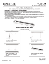
Fan diagram
Refer to the diagram below to identify the fan components. Note: Fan setup may differ from the illustration depending on the required
mounting method. The safety cable is not pictured below; however, it is an important part of the installation.
A. Upper mount. Secures the fan to the mounting structure.
B. Extension tube. Extends the fan from the ceiling and provides a path for wiring.
C. Upper mounting brace. Strengthens the upper mounting system.
D. Cover plate assembly. Provides access to wiring and includes a fan status LED and a switch used to change the direction of fan
rotation. The LED will ash an error code if there is a problem with the fan. See page 48 for LED error codes. See page 42 for
information on changing the fan direction.
E. Main fan unit. Includes the motor, hub, and power wiring.
F. Airfoil. Provides air movement. The unique, patented design provides efcient and effective air movement.
G. Winglet. Improves the efciency of the fan. Winglets are standard on Essence® fans; however, airfoil tips are available as on option.
Pre-Installation (cont.)
A
BD
E
F
G
C

7
ESSENCE®
WWW.BIGASSFANS.COM ©2013 DELTA T CORP. ALL RIGHTS RESERVED
Preparing the work site
When surveying the work site, keep the following mechanical and electrical guidelines in mind.
Mechanical
• A suitable means for lifting the weight of the fan, such as a scissor lift, and at least two installation personnel will be required.
• If hanging the fan from angle irons, the minimum dimensions of the angle iron must be 2-1/2’’ × 2-1/2’’ × 1/4’’
(6.4 cm × 6.4 cm × 0.6 cm) and it cannot be longer than 12 ft (3.6 m). It must be secured to the structure. Do not mount the fan to a
single purlin, truss, or bar joist. Consult a structural engineer for installation methods not covered in this manual.
• To reduce the risk of injury to persons, install the fan so that the airfoils are at least 10 ft (3.05 m) above the oor.
• If mounting the fan in the vicinity of an infrared/radiant heater, it is recommended that the fan be mounted outside of the clearances
recommended by the manufacturer of the heater and at a height equal to or above the shielding on the heating element with the
controller on the opposite side of the heater. If mounting the fan below the heater shielding, all fan elements must be outside of the
clearances recommended by the heater manufacturer. The installation manual for the specic model of heater will typically provide
the minimum clearance to combustibles (MCC).
• Adhere to the safety requirements in the table below when selecting where to mount the fan.
Safety requirement Minimum distances
Clearance ≥2 ft from all fan parts and ≥3 ft below sprinklers. The fan installation area must also be free of
obstructions such as lights, cables, or other building structure.
Blade height ≥10 ft above the floor
HVAC equipment ≥1x fan diameter if above diffuser. ≥2x fan diameter if below diffuser. Refer to the illustration below.
Fan spacing 2.5x fan diameter, center-to-center
Radiant/IR heaters See the manufacturer’s requirements for the minimum clearance to combustibles.
Pre-Installation (cont.)
Electrical
• Ensure power wiring is routed to a junction box at the fan location prior to installation.
• Essence® is shipped with either a 110–125 VAC motor or a 200–240 VAC motor. The fan’s voltage is marked on the fan packaging
and on the label on top of the main fan unit. The voltage cannot be changed during installation. Ensure your fan is the correct
voltage prior to beginning installation.
• Do NOT install the wall controller (wired or wireless) outdoors or in a location where it may come into contact with water.
• To optimize communication between the wireless wall controller and the fan(s), Big Ass Fans recommends installing the wireless
wall controller in a plastic junction box.
• To reduce the risk of electric shock, wiring should be performed by a qualied electrician! Incorrect assembly can cause electric
shock or damage the motor and the controller!
• Installation of a Big Ass Fan must be in accordance with the National Electrical Code (NEC), ANSI/NFPA 70-2011, and local codes.
• Do not install the wall controller if installing SmartSense. See the SmartSense Installation Guide for wiring and operating instructions.
HVAC
Diffuser
≥1x fan’s diameter (8 ft)
(2.4 m)
8-ft diameter
8-ft diameter
HVAC
Diffuser
≥2x fan’s diameter (16 ft) (4.9 m)
The fan is located at or above
the HVAC discharge or intake.
The fan is located below the
HVAC discharge or intake.
The fan should only be installed according to the instructions described in this manual. Consult a structural
engineer for installation methods not covered in this manual. For optional mounting methods, refer to the installation
instructions included with the fan parts.

ESSENCE®
WWW.BIGASSFANS.COM ©2013 DELTA T CORP. ALL RIGHTS RESERVED
8
1. Select proper angle irons
Follow the table below when selecting angle irons for fan installation. Note: Angle irons and angle iron hardware are not included with
the fan.
Angle iron span
(between mounting points)
Minimum angle iron dimensions
(W x H x T)
Number of angle
irons needed
6 ft (1.8 m) or less 2.5” (6.4 cm) x 2.5” (6.4 cm) x 0.25” (0.6 cm) 2
over 6 ft (1.8 m) to 8 ft (2.4 m) 3” (7.6 cm) x 3” (7.6 cm) x 0.25” (0.6 cm) 2
over 8 ft (2.4 m) to 12 ft (3.7 m) 3” (7.6 cm) x 3” (7.6 cm) x 0.25” (0.6 cm) 4*
*Two pairs of angle irons. Pairs should be placed back to back and fastened in center (see step 3).
Mounting Structure: Bar Joists
WARNING: The fan can weigh up to 120 lbs (54.4 kg). The fan should not be installed unless the structure on which the fan
is to be mounted is of sound construction, undamaged, and capable of supporting the loads of the fan and its method of
attachment. A structural engineer should verify that the mounting structure is adequate prior to fan installation. Verifying
the stability of the mounting structure is the sole responsibility of the customer and/or end user, and Big Ass Fans hereby
expressly disclaims any liability arising therefrom, or arising from the use of any materials or hardware other than those
supplied by Big Ass Fans or otherwise specied in these installation instructions.
CAUTION: Do not install the fan from a single purlin or truss or junction box.
CAUTION: Unsupported angle iron spans should not exceed 12 ft (3.7 m).
Angle Iron Side View
(see table for dimensions)
Width
Height Thickness
6’ (1.8m) or less
over 6’ (1.8m) – 8’ (2.4 m)
over 8’ (2.4 m) – 12’ (3.7 m)

9
ESSENCE®
WWW.BIGASSFANS.COM ©2013 DELTA T CORP. ALL RIGHTS RESERVED
Mounting Structure: Bar Joists (cont.)
3. Secure angle irons (if span is longer than 8 ft)
If the angle iron span is longer than 8 ft (2.4 m), it is necessary to
use double angle irons.
Locate the center of the angle iron length. Drill Ø 9/16” (1.4 cm) hole
through the center of the vertical wall of the angle iron. Drill a total of
four angle irons.
Place two drilled angle irons back to back. Fasten the angle irons
together with customer-supplied Grade 8 hardware.
Align the angle irons to each other and tighten the bolts to 25 ft·lb
(33.9 N·m) using a 3/4” socket with torque wrench.
Repeat step for remaining two angle irons.
Proceed to step 4b.
Angle Iron Hardware (Customer-Supplied):
a. (2) 1/2-13 or M12 Bolt
b. (4) 1/2” or M12 Washer
c. (2) 1/2” or M12 Nut
a
b
b
c
2. Pre-drill angle irons
Drill two Ø 7/16” (1.1 cm) holes exactly 5-1/2” (14 cm) apart in the centers of two angle irons.
Measure the distance between the mounting points of the roof structure that the angle irons will span. Measure the same distance on
the angle irons, and drill Ø 9/16” (1.4 cm) holes through each end of the angle irons. Drill holes in two angle irons if span is 8 ft (2.4 m)
or less. Drill holes in four angle irons if span is greater than 8 ft (2.4 m).
5-1/2’’ (14 cm)
Distance between roof structure mounting points
A1/2 A
Ø 9/16’’ (1.4 cm)
Side view
Ø 7/16’’ (1.1 cm)
If the angle iron span is 8 ft (2.4 m) or less, proceed to
step 4a on the following page.

ESSENCE®
WWW.BIGASSFANS.COM ©2013 DELTA T CORP. ALL RIGHTS RESERVED
10
4a. Fasten single angle irons to roof structure mounting points
CAUTION: The angle irons must be fastened to the roof structure at each end.
Fasten the angle irons to the roof structure mounting points at each end with customer-supplied Grade 8 hardware as shown. Do not
tighten the hardware until the fan has been mounted to the angle irons. Note: Big Ass Fans recommends orienting the angle irons
so that the horizontal legs are facing each other. Refer to the illustration below.
Proceed to "Hanging the Fan" on page 16.
Angle Iron Hardware (Customer-Supplied):
a. (4) 1/2-13 or M12 Bolt
b. (8) 1/2” or M12 Washer
c. (4) 1/2” or M12 Nut
b
a
d
b
c
Mounting Structure: Bar Joists (cont.)
Angle Iron Hardware (BAF-Supplied):
d. (8) 3” Square Washer (see diagram)
Square Washer
Thickness:
1/4” (6 mm)
3”
(7.6 cm)
3”
(7.6 cm)
Ø 9/16”
(1.4 cm)
If installation requires double angle irons, i.e., span is greater than 8 ft (2.4 m), proceed to step 4b.

11
ESSENCE®
WWW.BIGASSFANS.COM ©2013 DELTA T CORP. ALL RIGHTS RESERVED
4b. Fasten double angle irons to roof structure mounting points
CAUTION: The angle irons must be fastened to the roof structure at each end.
Fasten the angle irons to the roof structure mounting points at each end with customer-supplied Grade 8 hardware as shown. Do not
tighten the hardware until the fan has been mounted to the angle irons.
Proceed to "Hanging the Fan" on page 16.
Angle Iron Hardware (Customer-Supplied):
a. (8) 1/2-13 or M12 Bolt
b. (16) 1/2” or M12 Washer
c. (8) 1/2” or M12 Nut
A
b
a
d
b
c
Mounting Structure: Bar Joists (cont.)
Angle Iron Hardware (BAF-Supplied):
d. (8) 3” Square Washer (see diagram)
Square Washer
Thickness:
1/4” (6 mm)
3”
(7.6 cm)
3”
(7.6 cm)
Ø 9/16”
(1.4 cm)

ESSENCE®
WWW.BIGASSFANS.COM ©2013 DELTA T CORP. ALL RIGHTS RESERVED
12 Mounting Structure: Wood Frame
WARNING: The fan can weigh up to 120 lbs (54.4 kg). The fan should not be installed unless the structure on which the
fan is to be mounted is of sound construction, undamaged, and capable of supporting the loads of the fan and its method
of attachment. A structural engineer should verify that the structure is adequate prior to fan installation. Verifying the
stability of the mounting structure is the sole responsibility of the customer and/or end user, and Big Ass Fans hereby
expressly disclaims any liability arising therefrom, or arising from the use of any materials or hardware other than those
supplied by Big Ass Fans or otherwise specied in these installation instructions.
1. Identify mounting location
CAUTION: Do not install the fan from a single beam or a conduit box.
Locate the area on the beams from which the fan will hang. Big Ass Fans recommends mounting the fan so that the airfoils are at least
10 ft (3 m) from the oor. The center-to-center distance between the two beams between which the fan will hang cannot be greater than
24 in (61 cm).
2a. Fasten brackets (to vaulted ceiling beams)
Fasten the brackets to the roof structure mounting points at each end using the Wood Frame Mounting Hardware as shown. The
brackets should be pointing inward. Torque to 25 ft·lb (33.9 N·m).
Using a level and carpenter’s square, ensure the mounting brackets are level and the opposing holes are concentric.
Proceed to "Hanging the Fan" on page 16.
Wood Frame Mounting Hardware (BAF-Supplied):
a. (8) 5/16”-18 x 2-1/2” Bolt
b. (16) 5/16” Flat Washer
c. (8) 5/16”-18 Nylock Nut
cb
ba
Wood framing channels are mainly used in residential homes. Consult a structural engineer to ensure you have
selected the correct mounting method for your building structure.
/