Page is loading ...

INSTALLATION
GUIDE
HVLS Jet by Big Ass Fans
For help, call 1-877-BIG-FANS
or visit www.bigassfans.com

PRE-INSTALLATION CHECKLIST
I have the appropriate mount to accommodate the roof pitch and my building structure.
Big Ass Fans can only be mounted to I-beams or angle iron. Do not directly mount the fan to single
purlins, trusses, or bar joists. Consult a structural engineer for mounting methods not covered in
this manual.
A structural engineer approved the mounting structure.
The mounting structure must be able to withstand the torque forces generated by the fan. The
largest Big Ass Fan generates up to 300 ft·lb (406.7 N·m) of torque during operation.
I am familiar with the function of the safety cable.
If my fan’s extension tube is 4 ft (1.2 m) or longer or if the fan is installed near any building
fixtures, I will secure the fan with the provided guy wires as a safety measure.
The fan will be installed so that the airfoils are at least 10 ft (3.05 m) above the floor.
The fan will be installed so that the airfoils have a minimum of 2 ft (0.61 m) of clearance from
obstructions and the building structure.
The distance of the fan from the ceiling should be measured from the top of the winglets to the
ceiling.
The fan will be installed so that it is not subjected to high winds such as from an HVAC system
or near a large garage door.
If the fan is mounted at the same level or higher than a diuser, the winglets must be at a distance
that is at least 1x the measure of the fan’s diameter. If the fan is mounted at the same height or
below a diuser, the winglets must be at a distance that is at least 2x the measure of the fan’s
diameter.
The distance between multiple fans must be at least 2.5x the fans’ diameter when measured
from the centers of the fans.
The upper mount is the correct size for the I-beam.
The airfoils and other fan components are those that were shipped with the motor unit.
If installing multiple fans, do not mix and match fan components.
The supply power circuit is appropriate for the VFD, and power wiring is routed to the site of
fan and the controller installation.
See the specification label on the fan or consult the Owner’s Manual included in the fan box for
power requirements.

READ AND SAVE THESE INSTRUCTIONS
WARNING AND CAUTION SYMBOL
Indicates a hazard with a medium level of risk that could result in injury or death or damage
to property if not avoided.
ELECTRICAL WARNING SYMBOL
Indicates an electrical hazard with a medium level of risk that could result in death or serious
injury if not avoided.
This product was manufactured in a plant whose Management System is certified as being in conformity with ISO 9001.
Legal
Improper installation, delivery, or maintenance, including, but not limited to, any of the following actions by the customer or agent of the
customer will constitute a breach of and will void all warranties:
• Failure to follow the required installation procedures specified in this Installation Guide and in all other documentation supplied with
the fans and related equipment including documentation provided by the manufacturers of the individual fan and control components;
• Failure to follow all relevant codes and ordinances, including, but not limited to, the National Electric Code (United States), applicable
national and local electrical codes, and state and local building codes;
• Failure to follow electrical engineering industry standards regarding the approved method of installing solid-state electrical equipment
having the characteristics of the fans, the fan controls, and their related components, even if such standards are not specifically
referenced in any instructions or literature supplied by Big Ass Solutions or provided by manufacturers.
HVLS Jet is a trademark of Delta T Corporation. All other trademarks used herein are the properties of their respective owners. No part
of this document may be reproduced or translated into a dierent language without the prior written consent of Big Ass Solutions. The
information contained in this document is subject to change without notice. For the most up-to-date information, see the online installation
guide at www.bigassfans.com
www.bigasssolutions.com/patents ▪ www.bigasssolutions.com/warranties
Conforms to ANSI/UL STD 507: Electric Fans
Certified to CAN/CSA C22.2 Fans & Ventilators
Installation Guide
October 2016
Rev. B
Original English Instructions

IMPORTANT SAFETY INSTRUCTIONS
WARNING—TO REDUCE THE RISK OF FIRE, ELECTRIC SHOCK, OR INJURY TO PERSONS, OBSERVE THE
FOLLOWING:
WARNING: Installation work and electrical wiring must be done by qualified person(s) in accordance with all
applicable codes and standards, including fire-rated construction.
WARNING: When cutting or drilling into a wall or ceiling, do not damage electrical wiring and other hidden
utilities.
WARNING: The installation of all Big Ass Fan models covered under this manual must be installed in accordance
with the requirements specified in this installation manual and with all national and local electrical codes. Code
compliance is ultimately YOUR responsibility! Failure to comply with these codes could result in personal injury
or property damage.
WARNING: Before servicing or cleaning the fan, switch power o at service panel and lock the service
disconnecting means to prevent power from being switched on accidentally. When the service disconnecting
means cannot be locked, securely fasten a prominent warning device, such as a tag, to the service panel.
WARNING: Big Ass Fans must be installed with part(s) that are marked (on their cartons) to Indicate the suitability
with this model. Other similar part(s) cannot be substituted.
WARNING: This appliance is not intended for use by persons (including children) with reduced physical, sensory
or mental capabilities, or lack of experience and knowledge, unless they have been given supervision or
instruction concerning use of the appliance by a responsible person.
CAUTION: Exercise caution and common sense when powering the fan. Do not connect the fan to a damaged
or hazardous power source. Do not attempt to resolve electrical malfunctions or failures on your own. Contact
Big Ass Fans if you have any questions regarding the electrical installation of this fan.
CAUTION: Do not bend the airfoils when installing or servicing the fan. Do not insert foreign objects between
rotating airfoils.
CAUTION: Use this fan only in the manner intended by Big Ass Fans. If you have questions, contact Customer
Service.
CAUTION: Do not operate fan with damaged cord or plug. Return fan to authorized service facility for examination
or repair.
ATTENTION: If installing the fan in the United States, the fan must be installed per the following National Fire
Protection Association (NFPA) guidelines:
• The fan must be centered approximately between four adjacent sprinklers.
• The vertical distance from the fan to the sprinkler deflector must be at least 3 ft (91.4 cm).
• The fan must be interlocked to shut down immediately upon receiving a waterflow signal from the alarm
system.

CONTENTS
Introduction
Important Safety Instructions ii
Technical Specifications 1
Pre-Installation
Before Installing Your Fan 2
Parts and Hardware 3
Fan Diagram 4
Where to Install Your Fan 5
Installation
Overview 10
1a. Prepare the I-Beam 11
1b. Prepare the Angle Irons 12
2. Directly Mount Main Fan Unit to Angle Irons 15
3a. Attach Upper Mount to I-Beam 16
3b. Attach Upper Mount to Angle Irons 17
4. Attach the Extension Tube 18
5. Secure the Safety Cable 18
6. Attach Lower Yoke 19
7. Attach Main Fan Unit 19
8. Confirm Orientation 20
9. Install Guy Wires 20
10. Mount the Variable Frequency Drive (VFD) 23
11. Install the Electronic Programming Module (EPM) 24
12. Wire the Fan and VFD 24
13. Install the Airfoils 25
Electrical Guidelines
Cable Types 26
Grounding 27
Input Voltage Irregularities 27
Delta Secondary 28
Branch Circuit Protection 29
VFD Wiring: ESFR (Early Suppression Fast Response) 30
VFD Wiring: 100-125 V & 200-240 V, 1 Φ Controller 31
VFD Wiring: 200–240 V, 3 Φ Controller 32
VFD Wiring: 400-480 V, 3 Φ Controller 33
Daisy Chaining 34
Motor Wiring: 9-Lead, Dual Voltage, Wye Motor Configuration 35
Operating the
Controller
Starting and stopping the fan 36
Adjusting fan speed 36
Reversing direction of fan rotation 36
Operating the Fan
Heating Season 37
Cooling Season 37
Maintenance
Annual Preventative Maintenance 39
General Preventative Maintenance 39
Annual Maintenance Checklist 40

Troubleshooting
General Troubleshooting 41
Cutting the Extension Tube 42
Status and warning messages 43
Fault messages 44
179 diagnostics running display options 45
Warranty
Warranty Return Instructions 47
Warranty Claim Form Instructions 48
Warranty Claim Form 49
Responsibility Agreement 50
Check-In Procedure 51
Close-Out Procedure 53

WWW.BIGASSSOLUTIONS.COM © 2016 DELTA T CORP. ALL RIGHTS RESERVED.
1
TECHNICAL SPECIFICATIONS
Note: All controllers produce 3-phase output power regardless of input phase.
HVLS Jet
Diameter Motor Size Minimum Circuit Size Full Load Amps (Fan)
8 ft
(2.4 m)
1.0 hp
(0.75 kW)
25 A @ 100–125 V, 1 Φ
15 A @ 200–240 V, 1 Φ
10 A @ 200–240 V, 3 Φ
10 A @ 400–480 V, 3 Φ
8.8 A
8.8 A
5.0 A
2.5 A
10 ft
(3.0 m)
12 ft
(3.6 m)
1.5 hp
(1.1 kW)
25 A @ 200–240 V, 1 Φ
15 A @ 200–240 V, 3 Φ
10 A @ 400–480 V, 3 Φ
13.3 A
8.1 A
4.1 A
14 ft
(4.3 m)
16 ft
(4.9 m)
2.0 hp
(1.5 kW)
25 A @ 200–240 V, 1 Φ
15 A @ 200–240 V, 3 Φ
10 A @ 400–480 V, 3 Φ
13.3 A
8.1 A
4.1 A
18 ft
(5.5 m)
20 ft
(6.1 m)
24 ft
(7.3 m)

WWW.BIGASSSOLUTIONS.COM © 2016 DELTA T CORP. ALL RIGHTS RESERVED.
2
BEFORE INSTALLING YOUR FAN
Review the following pre-installation procedures and checks to ensure you have all necessary items for installation.
Tools
The largest Big Ass Fan weighs a maximum of 415 lbs (188 kg). A suitable means for lifting the weight of the fan,
such as a scissor lift, at least two personnel, and the following tools will be required. Note: Depending on you
application, additionally tools may be required.
☐ Standard wrench set
☐ Standard socket set and ratchet
☐ Torque wrench capable of 40 ft·lb (54.2 N·m) & 3/4” socket
☐ Phillips and flat head screwdrivers
☐ Standard allen wrench set
☐ 1/4” nut driver
☐ 5/16” nut driver
☐ #10 to #14 AWG strippers
☐ Medium channel locks
☐ Multimeter
Power supply guidelines
If you are unfamiliar or uncomfortable with the installation of electrical components, do not attempt to install the
fan without an electrician. This guide is merely a recommendation of proper installation.
✓ Dedicated Branch Circuit Protection. Each fan requires dedicated branch circuit protection.
✓ Circuit Requirements. Refer to the Owner’s Manual and fan label for appropriate circuit requirements for your
fan size.
✓ Conduit. Controller output/motor input leads cannot share a conduit with any other controller’s AC supply feed.
✓ Local Disconnect. If required, a local disconnect should be installed per NEC and all local codes.
✓ Onboard VFD. If you are installing an onboard variable frequency drive (VFD), route the power wiring to the
location where the fan will be mounted.
✓ Manual Disconnect. To satisfy some local code requirements, it may be necessary to install a manual disconnect
at the fan motor location when the fan assembly is not within “line-of-sight” from the VFD. A non-fused, 600 V,
3-phase, blade style disconnect should be used to satisfy this “line-of-sight” requirement.
Power wiring guidelines
✓ To reduce the risk of electric shock, wiring should be performed by a qualified electrician. Incorrect assembly
can cause electric shock or damage to the motor or controller.
✓ The electrical installation of the fan must be in accordance with the National Electrical Code, ANSI/NFPA 70-
2014, if applicable, and all local codes.
✓ See the Electrical Installation section for complete input power guidelines.

WWW.BIGASSSOLUTIONS.COM © 2016 DELTA T CORP. ALL RIGHTS RESERVED.
3
Hardware
Fan hardware for hanging the fan and airfoils is provided on hardware boards. Verify you have all of the following
required hardware before beginning the installation process.
Mounting Hardware Board
1
Upper Mount Hardware
• (4) 1/2-13 x 2” Bolts
• (8) 1/2” Flat Washers
• (4) 1/2-13 Nylock Nuts
Safety Cable Shackle
Extension Tube Hardware
• (2) 1/2-13 x 4-1/2” Bolts
• (4) 1/2” Flat Washers
• (2) 1/2-13 Nylock Nuts
Lower Yoke Hardware
• (2) 1/2-13 x 4-1/2” Bolts
• (4) 1/2” Flat Washers
• (2) 1/2-13 Nylock Nuts
Motor Unit Hardware
• (4) 1/2-13 x 1-3/4” Bolt
• (8) 1/2” Flat Washer
• (4) 1/2-13 Nylock Nut
Airfoil and Winglet Hardware Boards
Airfoil Hardware
• (12) 5/16-18 x 2’’ GR 8 Bolt
• (24) 5/16” Flat Washer
• (12) 5/16-18 Nylock Nut
Winglet Hardware
• (6) 10-24 x 3/4” Barrel
• (6) 10-24 x 1/2” Bolt
Guy Wire Hardware
2
• Locking Carabiners
• 1/4” Beam Clips
• 1/4-20 x 1” Eyebolts
• 1/4-20 Hex Nuts
• Gripples
• Guy Wires
• Wire Rope Clips
1. Square washers are included and are only used if you are mounting the fan to angle irons. The number of square washers used depends on the number of angle irons used.
2. Guy wires and hardware are only included with your order if the fan’s lateral movement needs to be restrained. Big Ass Fans recommends using guy wires if the extension tube
is four feet or longer, or if the fan is exposed to high winds or similar conditions, or if the fan is near building structural components.
Parts
Check that the fan boxes have all the parts before beginning installation. If you ordered multiple fans, be sure
to keep the components of each fan together. The fans each have dierently rated components that are not
interchangeable. Note: Illustrations are not to scale.
(2) Beam Clip
(2) Spacer
Upper Mount
1
Lower Yoke EPM Module &
Fire Relay
2
Winglets
Airfoils Airfoil Retainers Wall Controller Main Fan Unit Extension Tube
3
1. The upper mount may dier from the picture. Confirm that you have the appropriate mount for your roof pitch.
2. The fire relay is not shown. If multiple fans are to be installed, make sure to install the exact EPM included with the fan’s packaging. EPMs are not interchangeable!
3. The safety cable is preattached to the extension tube (or packaged separately if the extension tube was not ordered).

WWW.BIGASSSOLUTIONS.COM © 2016 DELTA T CORP. ALL RIGHTS RESERVED.
4
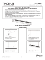
FAN DIAGRAM
Contact Customer Service if you are missing any parts or hardware needed for installation.
A
Safety Cable
E
Extension Tube
I
Airfoil
B
Beam Clips & Spacers
F
Motor
C
Upper Mount
G
Hub
D
Lower Yoke
H
Winglet
A
B
C
D
E
G
I
H
F

WWW.BIGASSSOLUTIONS.COM © 2016 DELTA T CORP. ALL RIGHTS RESERVED.
5
WHERE TO INSTALL YOUR FAN
Before beginning installation, check that the building structure and fan location meet Big Ass Solutions’ safety
guidelines by confirming the below requirements.
☐ Fans mounted on fabricated I-beams, which are common in steel buildings, could cause the beam to flex and
the fan to move significantly during operation. If this flexing causes a clearance problem, we suggest installing
the I-Beam Stabilizer Kit. Contact Customer Service for more information.
☐ The fan’s lateral movement must be secured using guy wires if the fan’s extension tube is 4 ft (1.2 m) or longer
or if the mounting structure requires it. If the fan is close to any building fixtures it is recommended to secure
the fan with guy wires as a safety measure.
☐ The fan must be installed so that it is plumb to the ground
☐ All fan parts must be ≥ 2 ft (61 cm) from all obstructions. The fan installation area must be free of obstructions
such as lights, cables, sprinklers, or other building structure components.
☐ The fan must be installed so that it is ≥ 10 ft (3 m) above the finished floor.
☐ Review the Mounting Reference Guide in your Owner’s Manual to ensure you have the appropriate mount.
Clearance guidelines
If your fan application does not meet these requirements, contact Customer Service to discuss alternative
installations or other fan options.
General clearance
☐ Multiple fans must be spaced at a center-to-center distance that is no less than 2.5x the fan diameter.
☐ The fan must be installed so that it is ≥ 10 ft (3 m) above the finished floor.
Ceiling clearance
The fans must be installed at the distance listed below according to your fan size. The distance of the fan from the
ceiling should be measured from the top of the winglets to the ceiling.
Fan Diameter Distance from Ceiling
8–14 ft (2.4–4.3 m) 5 ft (1.5 m)
16–18 ft (4.9–5.5 m) 6 ft (1.8 m)
20–24 ft (6.1–7.3 m) 7 ft (2.1 m)

WWW.BIGASSSOLUTIONS.COM © 2016 DELTA T CORP. ALL RIGHTS RESERVED.
6
Clearance from HVAC equipment and radiant heaters
The fan must be installed at the minimum distances shown below in relation to HVAC (Heating, Ventilation, and
Cooling) systems. See the manufacturer’s requirements for the minimum clearance to combustibles.
Fan located at or above HVAC discharge or intake
If the fan is at the same level or above the HVAC diuser, it must have a clearance of ≥1x fan’s diameter.
≥ 2 x fan’s diameter
40 ft (12.1 m)
Fan located below HVAC discharge or intake
If the fan is located below the HVAC diuser, it must have a clearance of ≥2x the fan’s diameter.
Diameter:20 ft (6.1 m)
HVAC
Diuser
HVAC
Diuser
≥ 1 x fan’s diameter
20 ft (6.1 m)
Diameter: 20 ft (6.1 m)

WWW.BIGASSSOLUTIONS.COM © 2016 DELTA T CORP. ALL RIGHTS RESERVED.
7
Standard Upper Mount 90-Degree Oset Mount
Understanding roof pitch
To ensure your fan is properly mounted, it must hang plumb to the ground with the upper mount installed using
the bolt holes at the widest locations possible. To accommodate building structures on which the standard upper
mount does not allow the fan to properly orient itself, the 90-Degree Oset mount should be purchased.
The example below shows a situation in which the 90-Degree Oset mount must be used so that the fan hangs
plumb to the ground. If you are uncertain of your roof pitch or do not have the correct mount to properly hang your
fan, consult a structural engineer or contact Big Ass Fans Customer Service.

WWW.BIGASSSOLUTIONS.COM © 2016 DELTA T CORP. ALL RIGHTS RESERVED.
8
Understanding airflow patterns
Correct fan placement is crucial for maximizing airflow distribution while adhering to safety standards.
Airflow in an open area
The airflow moves from the fan toward the floor.
When airflow hits the floor, it moves outward in
all directions. The deflection of air o the floor is
called a “floor jet.”
Airflow in an enclosed area
The floor jet radiates outward until it reaches the
walls, which deflect the jet upward. After it hits
the ceiling, the upward flow is directed inward
to the low pressure area above the fan where
it is then pulled down toward the floor. This
creates a convection-like air current that gathers
momentum. Once this current is established,
the fan begins to move air outside the current,
escalating its cooling eects.
Airflow with multiple fans
Where there are multiple fans appropriately
spaced, the expanding jets of adjacent fans meet
to create a pressure zone. The pressure zone
acts like a wall, causing each fan to behave like
a single enclosed fan. Typically, a single fan’s
performance will increase when working in
conjunction with other fans.
Airflow with streamlined obstruction
Obstructions on the floor tend to block the
horizontally moving air. Thin or streamlined
obstructions do not block much airflow, regardless
of size. The air tends to flow smoothly around
these obstructions, losing little momentum, and
leaving only a small stagnant area behind the
obstruction.
Airflow with wide, blunt obstruction
A wide, blunt, or flat-faced obstruction forces
the air to change direction, turning upward and
outward. There is a stagnant area behind these
obstructions that is wider and higher than the
obstructions themselves.

WWW.BIGASSSOLUTIONS.COM © 2016 DELTA T CORP. ALL RIGHTS RESERVED.
9
General airflow tips
Below are some techniques that make a dramatic dierence in congested areas of your facility. Treat air like water,
and scoop, direct, and channel it to where it is needed most.
• Make sure people are not hidden behind structures that would block airflow. This may seem obvious, but work
areas are routinely blocked by shelving, crates, and machinery.
• Position large obstructions so that their smallest profiles are perpendicular to the direction of air movement. For
example, a sheet metal press brake might have five times the frontal area if it is facing the airflow rather than if
it is turned sideways.
• Wherever possible, position welding curtains, partitions, sheet materials, etc., to scoop air into the work area
rather than deflect it.
• Take advantage of the air moving near the floor by creating ground level openings in your work area. It is better
to have a work area blocked by materials stacked to the ceiling with an opening below than to have low stacks
3 ft (0.9 m) to 6 ft (1.8 m) high sitting on the floor.

WWW.BIGASSSOLUTIONS.COM © 2016 DELTA T CORP. ALL RIGHTS RESERVED.
10
INSTALLATION
WARNING: The fan should not be installed unless the structure on which the fan is to be mounted is
of sound construction, undamaged, and capable of supporting the loads of the fan and its method of
mounting. A structural engineer should verify that the structure is adequate prior to fan installation.
Verifying the stability of the mounting structure is the sole responsibility of the customer and/or end
user, and Big Ass Fans hereby expressly disclaims any liability arising therefrom, or arising from the use
of any materials or hardware other than those supplied by Big Ass Fans or otherwise specified in these
installation instructions.
CAUTION: Before beginning installation, confirm that you have the appropriate mount for your roof pitch.
WARNING: Ensure there are no persons below the fan unit during installation!
Overview
Big Ass Fans can only be hung from an I-beam or angle irons. Consult a structural engineer for installation methods
not covered in this manual. Follow the steps on the following pages to install your fan.
I-Beam Angle Irons
• It is not recommended to mount a Big Ass Fan
to a fabricated I-beam. Do not direct mount
the fan to an I-beam. The I-beam on which
the fan will mount must be part of the existing
building structure.
• Do not install the fan from a single purlin,
truss, or bar joist.
• Unsupported angle iron spans should not
exceed 12 ft (3.7 m).
• The angle irons must be fastened to the roof
structure at each end.

WWW.BIGASSSOLUTIONS.COM © 2016 DELTA T CORP. ALL RIGHTS RESERVED.
11
outer holes
middle holes
inner holes
Upper Mount
(top view)
1a. Prepare I-Beam
ATTENTION
If you are mounting your fan to angle irons, proceed to the following page.
Measure the flange width of the I-beam from which the fan will be hung. Select the mounting holes that match the
flange width of the I-beam from the diagrams below.
Proceed to step 2.
Small Upper Mount
13-3/4’’ x 10” (349 mm x 258 mm)
I-Beam Flange Width Mounting Holes
5” to 6-5/8”
(127 to 168 mm)
Inner holes
> 6-5/8” to 8-1/4”
(> 168 to 210 mm)
Middle holes
> 8-1/4” to 9-7/8”
(> 210 to 250 mm)
Outer holes
Large Upper Mount
18-1/2’’ x 10” (470 mm x 258 mm)
I-Beam Flange Width Mounting Holes
9-7/8” to 11-3/8”
(250 to 289 mm)
Inner holes
> 11-3/8” to 13”
(> 289 to 330 mm)
Middle holes
> 13” to 14-5/8”
(> 330 to 371 mm)
Outer holes

WWW.BIGASSSOLUTIONS.COM © 2016 DELTA T CORP. ALL RIGHTS RESERVED.
12
1b. Prepare the Angle Irons
CAUTION: Do not install the fan from a single purlin, truss, or bar joist.
CAUTION: Unsupported angle iron spans should not exceed 12 ft (3.7 m).
CAUTION: The angle irons must be fastened to the roof structure at each end.
If you are mounting your fan to an I-Beam, see the previous page. Consult a structural engineer for installation
methods not covered in this manual.
A. Select proper angle irons
Follow the table below when selecting angle irons for fan installation. Note: Angle irons and angle iron hardware
are not included with the fan.
Angle iron span
(between mounting points)
Minimum Angle Iron dimensions
(W x H x T)
Number of angle
irons needed
6 ft (1.8 m) or less 2.5” (6.4 cm) x 2.5” (6.4 cm) x 0.25” (0.6 cm) 2
6 ft to 8 ft (1.8 m to 2.4 m) 3” (7.6 cm) x 3” (7.6 cm) x 0.25” (0.6 cm) 2
8 ft to 12 ft (2.4 m to 3.7 m) 3” (7.6 cm) x 3” (7.6 cm) x 0.25” (0.6 cm) 4*
*Two pairs of angle irons needed.
6 ft (1.8 m) or less
over 6–8 ft (1.8–2.4 m)
over 8–12 ft (2.4 m–3.7 m)
Angle Iron Side View
(see table for dimensions)
Width
Height
Thickness

ab
b
c
WWW.BIGASSSOLUTIONS.COM © 2016 DELTA T CORP. ALL RIGHTS RESERVED.
13
B. Pre-drill angle irons
Before drilling the angle irons, confirm that you have the appropriate mount to accommodate the roof
pitch of your mounting structure.
Drill two Ø9/16” (1.4 cm) holes exactly 5-3/8” (13.7 cm) apart in the centers of two angle irons.
Measure the distance between the mounting points of the roof structure that the angle irons will span. Measure
the same distance on the angle irons and drill Ø9/16” (1.4 cm) holes through each end of the angle irons. Drill holes
in two angle irons if the span is 8 ft (2.4 m) or less. Drill holes in four angle irons if span is greater than 8 ft (2.4 m).
C. Fasten angle irons together (if span is longer than 8 ft [2.4 m])
If the angle iron span is 8 ft (2.4 m) or less, skip this step and proceed to step D.
If the angle iron span is longer than 8 ft (2.4 m), use double angle irons. Locate the center of the angle iron length.
Drill a Ø9/16” (1.4 cm) hole through the center of the vertical wall of the angle iron. Drill a total of four angle irons.
Place two drilled angle irons back to back. Fasten the angle irons together with Ø1/2-13 Grade 8 hardware. Align
the angle irons to each other and tighten the bolts to 40 ft·lb (54.2 N·m) using a torque wrench and 3/4” socket.
Repeat this step for the remaining two angle irons.
Proceed to step D.
Grade 8 Hardware (Installer-Supplied):
a. (2) 1/2-13 Bolt
b. (4) 1/2” Washer
c. (2) 1/2-13 Nylock Nut
Mount with extension tube: 5-3/8’’ (13.7 cm)
Direct mount: 5-1/2’’ (14 cm)
Distance between roof structure
mounting points
A
1/2 A
Ø 9/16’’ (1.4 cm)
Side view

Double Angle Irons
a
b
b
d
Square Washer
Thickness:
1/4” (6 mm)
3”
(7.6 cm)
3” (7.6 cm)
Ø 9/16”
(1.4 cm)
a
b
c
b
d
Vertical walls are
to the outside
Single Angle Irons
c
WWW.BIGASSSOLUTIONS.COM © 2016 DELTA T CORP. ALL RIGHTS RESERVED.
14
D. Fasten angle irons to roof structure mounting points
Single Angle Iron
Fasten the angle irons to the roof structure mounting
points at each end with Grade 8 hardware as shown.
Do not tighten the hardware until the upper mount
has been mounted to the angle irons (step 5). We
recommend orienting the angle irons so that the
horizontal legs are facing each other (or the vertical
legs are on the outside). Proceed to step 5.
Grade 8 Hardware (Installer-Supplied):
a. (4) 1/2-13 Bolt
b. (8) 1/2” Washer
c. (4) 3” Square Washer (supplied; see diagram)
d. (4) 1/2-13 Nylock Nut
Double Angle Iron
Fasten the angle irons to the roof structure mounting
points at each end with Grade 8 hardware as shown.
The angle irons with fan mounting holes should be
positioned on the inside, facing each other. Do not
tighten the hardware until the upper mount has
been mounted to the angle irons.
Grade 8 Hardware (Installer-Supplied):
a. (8) 1/2-13 Bolt
b. (16) 1/2” Washer
c. (8) 3” Square Washer (supplied; see diagram)
d. (8) 1/2-13 Nylock Nut
/