Page is loading ...

®
High Volume, Low Speed Ceiling Fans
®
Installation, Operation and Maintenance Manual
Please read and save these instructions for future reference. Read carefully before attempting to assemble, install,
operate or maintain the product described. Protect yourself and others by observing all safety information. Failure
to comply with these instructions will result in voiding of the product warranty and may result in personal injury
and/or property damage.
1
Document 483568
Model DS
High Volume, Low Speed Ceiling Fans
Models DS-3 and DS-6 are the ideal choice for providing year-round comfort in air circulation and destratification
applications. Featuring an aerodynamic, extruded aluminum airfoil design and a high efficiency direct drive motor,
model DS delivers maximum airflow at a fraction of the operating cost of other HVLS fans. And, with its universal
ceiling mount, the DS fan is the easiest HVLS fan to install in the market!
IMPORTANT: To reduce the risk of fire, electric shock,
or injury to persons, Model DS fans must be installed
with a mount assembly, motor assembly and airfoils that
are marked (on their cartons) to indicate suitability with
this model. Other mounts, motors, and airfoils cannot
be substituted.
WARNING
To reduce the risk of fire, electric shock, or injury to
persons, observe the following:
1. Use this unit only in the manner intended by the
manufacturer. If you have questions, contact the
manufacturer.
2. Before servicing or cleaning unit, switch
power off at service panel and lock the service
disconnecting means to prevent power from
being switched on accidentally. When the service
disconnecting means cannot be locked, securely
fasten a prominent warning device, such as a tag,
to the service panel.
WARNING
To reduce the risk of fire, electric shock, or injury to
persons, observe the following:
1. Installation work and electrical wiring must be
done by qualified person(s) in accordance with all
applicable codes and standards, including fire-
rated construction.
2. When cutting or drilling into wall or ceiling, do
not damage electrical wiring and other hidden
utilities.
WARNING
This appliance can be used by children aged from 8
years and above and persons with reduced physical,
sensory or mental capabilities or lack of experience
and knowledge if they have been given supervision or
instruction concerning use of the appliance in a safe
way and understand the hazards involved. Children
shall not play with the appliance. Cleaning and user
maintenance shall not be made by children without
supervision.
General Safety Information
IMPORTANT: DS fans must be installed with the supplied CAT-5e communication cable or shielded CAT-5e
(by others) that complies with the following specifications. Cable must be twisted pair, shielded 26 ga. CAT-5e
cable with a drain wire and must be compliant with ISO 11801. Cable must use shielded RJ45 connectors with
a soldered drain and wiring configuration must follow EIA/TIA T568B wiring pinout. Individual CAT-5e cable
lengths must not exceed 200 ft. in order to prevent network communication issues.

High Volume, Low Speed Ceiling Fans2
®
AVERTISSEMENT
Pour réduire le risque d’incendie, de choc électrique
ou de blessure corporelle, respecter ce qui suit :
1. Utiliser cet appareil exclusivement comme
prévu par le fabricant. En cas de questions,
communiquer avec le fabricant.
2. Avant tout entretien ou nettoyage de l’appareil,
couper l’alimentation sur le tableau de
commande et verrouiller le dispositif de
sectionnement pour empêcher toute mise
sous tension accidentelle. Si le dispositif de
sectionnement ne peut pas être verrouillé,
attacher un moyen de mise en garde bien visible,
tel qu’un panonceau, au tableau de commande.
AVERTISSEMENT
Pour réduire le risque d’incendie, de choc électrique
ou de blessure corporelle, respecter ce qui suit :
1. La pose et le câblage électrique doivent être
effectués par des personnes qualifiées en
conformité avec les codes et normes en vigueur,
y compris pour la résistance au feu du bâtiment.
2. Lors de la découpe ou du perçage de murs
ou plafonds, ne pas endommager les câbles
électriques et autres conduites masquées.
AVERTISSEMENT
Cet appareil peut être utilisé par des enfants âgés
de 8 ans et plus et par des personnes aux capacités
physiques, sensorielles ou mentales réduites ou qui
manquent d’expérience et de connaissances s’ils sont
surveillés ou ont reçu des instructions concernant
l’utilisation sécuritaire de l’appareil et comprennent
les risques encourus. Les enfants ne doivent pas
jouer avec l’appareil. Le nettoyage et l’entretien par
l’utilisateur ne doivent pas être effectués par des
enfants sans surveillance.
Only qualified personnel should install this fan.
Personnel should have a clear understanding of these
instructions and should be aware of general safety
precautions. Improper installation can result in electric
shock, possible injury due to coming in contact with
moving parts, as well as other potential hazards. Other
considerations may be required if high winds or seismic
activity are present. If more information is needed,
contact a licensed professional engineer before moving
forward.
1. Follow all local electrical and safety codes, as
well as the National Electrical Code (NEC) and the
National Fire Protection Agency (NFPA), where
applicable. Follow the Canadian Electric Code
(CEC) in Canada.
2. The rotation of the impeller is critical. It must
be free to rotate without striking or rubbing any
stationary objects.
3. Motor must be securely and adequately grounded.
4. Do not allow the power cable to kink or come in
contact with oil, grease, hot surfaces or chemicals.
Replace cord immediately if damaged.
5. Verify that the power source is compatible with the
equipment.
DANGER
Always disconnect, lock, and tag power source before
installing or servicing. Failure to disconnect power
source can result in fire, shock or serious injury.
CAUTION
When servicing the fan, motor may be hot enough
to cause pain or injury. Allow motor to cool before
servicing.
CAUTION
Precaution should be taken in explosive atmospheres.
DANGER
Pour écarter les risques d’incendie, de choc électrique
ou de blessure grave, veiller à toujours débrancher,
verrouiller et étiqueter la source de courant avant
l’installation ou l’entretien.
ATTENTION
Lors de toute intervention sur la soufflante, le moteur
peut être suffisamment chaud pour provoquer une
douleur voire une blessure. Laisser le moteur refroidir
avant toute maintenance.
ATTENTION
Faire preuve de précaution dans les atmosphères
explosives.
Receiving
Upon receiving the product, check to ensure all items
are accounted for by referencing the delivery receipt or
packing list. Inspect each crate or carton for shipping
damage before accepting delivery. Alert the carrier of
any damage detected. The customer will note damage
(or shortage of items) on the delivery receipt and all
copies of the bill of lading which is countersigned by
the delivering carrier. If damaged, contact your local
representative immediately. Any physical damage to
the unit after acceptance is not the responsibility of the
manufacturer.
Unpacking
Verify that all required parts and the correct quantity of
each item have been received using the component list
on pages 5-6. If any items are missing, report shortages
to your local representative to arrange for obtaining
missing parts. Sometimes it is not possible that all
items for the unit be shipped together due to availability
of transportation and truck space. Confirmation of
shipment(s) must be limited to only items on the bill of
lading.

High Volume, Low Speed Ceiling Fans 3
®
Storage
Fans are protected against damage during shipment. If
the unit cannot be installed and operated immediately,
precautions need to be taken to prevent deterioration of
the unit during storage. The user assumes responsibility
of the fan and accessories while in storage. The
manufacturer will not be responsible for damage during
storage. These suggestions are provided solely as a
convenience to the user.
Indoor - The ideal environment for the storage of
fans and accessories is indoors, above grade, in a low
humidity atmosphere that is sealed to prevent the entry
of blowing dust, rain or snow. Temperatures should be
evenly maintained between 30° to 110°F (-1° to 43°C).
Wide temperature swings may cause condensation
and “sweating” of metal parts. All accessories must be
stored indoors in a clean, dry atmosphere.
Remove any accumulations of dirt, water, ice or snow
and wipe dry before moving to indoor storage. To avoid
“sweating” of metal parts, allow cold parts to reach
room temperature. To dry parts and packages, use a
portable electric heater to get rid of any moisture build
up. Leave coverings loose to permit air circulation and
to allow for periodic inspection.
The unit should be stored at least 3-1/2 in. (89 mm) off
the floor on wooden blocks covered with moisture proof
paper or polyethylene sheathing. Aisles between parts
and along all walls should be provided to permit air
circulation and space for inspection.
Inspection & Maintenance During Storage
While in storage, inspect fans once per month. Keep a
record of inspection and maintenance performed.
If moisture or dirt accumulations are found on parts,
the source should be located and eliminated. If paint
deterioration begins, consideration should be given to
touch-up or repainting. Fans with special coatings may
require special techniques for touch-up or repair.
Machined parts coated with rust preventive should be
restored to good condition promptly if signs of rust
occur. Immediately remove the original rust preventive
coating with petroleum solvent and clean with lint free
cloths. Polish any remaining rust from surface with
crocus cloth or fine emery paper and oil. Do not destroy
the continuity of the surfaces. Thoroughly wipe clean
with Tectyl
®
506 (Ashland Inc.) or the equivalent. For
hard to reach internal surfaces or for occasional use,
consider using Tectyl
®
511M Rust Preventive, WD-40®
or the equivalent.
Removing from Storage
As fans are removed from storage to be installed in their
final location, they should be protected and maintained
in a similar fashion until the fan equipment goes into
operation.
IMPORTANT: Consult all applicable national, state
and local codes to ensure that all necessary code
requirements are met. It is the sole responsibility of the
installer to ensure compliance with applicable codes.
Prior to installing the fan, perform each of the following
checks:
1. Verify that fan components are undamaged. Do not
install or operate any damaged fan components,
fans, or fan accessories. Failure to comply with
this instruction may result in property damage,
personal injury and/or death.
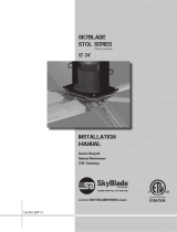
2. Verify that the fan is to be installed in a location
where the airfoils will be a minimum of 10 ft.
above the finished floor with a minimum of
3ft. of horizontal and vertical clearance to any
obstructions.
3. Verify that the fan is to be installed in a location
where the center of the fan is a minimum of 1.5 fan
diameters away from building walls and corners.
4. For best performance, the fan must be installed
with a two fan diameter minimum clearance to
radiant heaters and HVAC system discharges or
intakes.
5. Check that the fan will not be mounted in a location
near overhead doors or other building openings
where gusts of wind may occur. Fan should not
be installed or operated in locations where wind is
present.
6. If the building is equipped with a fire sprinkler
system, verify that the placement of the fan will
not interfere with correct sprinkler operation and
that the fan installation complies with all national,
state and local codes. For NFPA 13 compliance,
fan must be installed in the center of four adjacent
sprinklers with at least 3 ft. of vertical clearance
between the fan and sprinkler deflectors. Fan must
also be interlocked to shut down upon receiving a
waterflow signal from the building’s alarm system.
7. Check to see if the intended placement of the fan
is directly below any building lights or skylights. If
possible, avoid installing fan directly below a light
source to prevent a strobing effect that can be
caused by fan rotation.
8. If the building has a mezzanine or other elevated
spaces that may be occupied by people, verify that
no component of the fan can be reached from the
highest level or deck. The fan must be positioned
Pre-Installation Checks

High Volume, Low Speed Ceiling Fans4
®
B
A
3 FT. CLEARANCE AROUND BLADES
2X FAN DIAMETER
FROM HVAC
MINIMUM 10 FT. ABOVE
FINISHED FLOOR
HVAC
DIFFUSER
WHEN FULL DIFFUSER OUTLET
IS BELOW HVLS FAN,
HVLS FAN MUST BE 1X FAN DIAMETER AWAY
3 FT. CLEARANCE AROUND BLADES
Minimum Spacing Requirements
Minimum Spacing From Center of Fan (ft.)
Fan Size (ft.) A B
8 12 24
10 15 30
12 18 36
14 21 42
16 24 48
18 27 54
20 30 60
24 36 72
so that the tips of the airfoils are a minimum of 3ft.
away from the furthest point that a person could
reach or otherwise come in contact, to prevent
injury.
9. If the fan is to be mounted in an area where
materials or equipment may be elevated into its
path, ensure that the floor is marked or painted
to alert personnel of the overhead location of the
fan(s).
10. Before installation, it is important to verify that the
mounting surface will bear the operating weight
and maximum torque (twisting force) of the unit.
The Structural Engineer of Record (SEOR) must
perform a thorough evaluation of the mounting
structure and determine all final mounting
requirements before the fan is installed. It is the
sole responsibility of the installer to ensure that the
mounting structure and fan installation method are
adequate for safe operation of the fan.
Fan Size
(ft.)
DS-3 DS-6
*Max. Fan
Weight (lbs)
Max Torque
(ft∙lbf)
*Max. Fan
Weight (lbs)
Max. Torque
(ft∙lbf)
8 170 5.4 195 9.6
10 175 12.8 204 20.8
12 181 23.0 213 31.8
14 187 30.6 222 40.4
16 192 36.7 231 48.4
18 196 43.1 240 55.4
20 201 50.6 270 122
24 210 54.0 287 125.3
*Maximum weight is shown in pounds and includes all available
options, actual fan weight may be less.

High Volume, Low Speed Ceiling Fans 5
®
Verify that all of the following parts and hardware
have been received prior to beginning installation.
Contact your local representative or the manufacturer if
replacement parts are required.
NOTE: Additional parts (provided by others) may be
required to complete the fan installation, including
additional wiring, steel angle or Unistrut
®
channel, and
hardware for connecting the fan mount to the building
structure.
NOTE: Hardware quantities listed below indicate what
is required to complete installation. Hardware kits may
include extra fasteners as a convenience.
Fan Components
POWER CABLE
LIGHT POWER CABLE
(OPTIONAL)
FACTORY INSTALLED VFD
FIRE ALARM LANDING POINT
COMMUNICATION CABLE
WITH RJ45 SPLITTER
LIGHT POWER PLUG
(OPTIONAL)
LIGHT COMMUNICATION PLUG
(OPTIONAL)
Downtube and Mount Assembly (1)
Airfoil Blade (3 OR 6)
Winglet (3 OR 6)
AIRFOIL BLADE
SCREW BOSSES
WINGLET
#10 - 12 x 3/4 in. SCREW
(2 PER BLADE)
Rear VFD Cover (1)
DOWNTUBE & MOUNT ASSEMBLY
MOTOR & HUB ASSEMBLY
FRONT VFD COVER
REAR VFD COVER
M4 - 0.7 x 10 MACHINE SCREW
POWER CABLE
(PLUG OPTIONAL)
LIGHT POWER CABLE
(OPTIONAL)
SAFETY CABLE WITH
NO. 4 GRIPPLE
®
FACTORY INSTALLED VFD
FIRE ALARM LANDING POINT
COMMUNICATION CABLE
WITH RJ45 SPLITTER
LIGHT POWER PLUG
(OPTIONAL)
LIGHT COMMUNICATION PLUG
(OPTIONAL)
CAT-5e Control
Cable (1)
Hub Plate (1)
LOGO PLATE
U-NUT
HUB RETENTION BRACKET
1/4 - 20 x 1 STAINLESS STEEL MACHINE SCREW
DS-3
DS-6
Motor/Hub Assembly (1)
Bag # 916290
DOWNTUBE & MOUNT ASSEMBLY
UG2 GRIPPLE
®
TURNBUCKLE
GUY WIRE
GUY WIRE
GUY WIRE
GUY WIRE CLAMP ASSEMBLY
GUY WIRE CLAMP BOLT
45º to 60º
TURNBUCKLE
GUY WIRE ATTACHMENT RING
QUICK LINK
CABLE CLAMP
QUICK LINK
U-Bolt Steel Cable
Clamps (10)
20 Ft.
Guy Wire (4)
DOWNTUBE & MOUNT ASSEMBLY
GUY WIRE
GUY WIRE
GUY WIRE CLAMP ASSEMBLY
GUY WIRE CLAMP BOLT
45º to 60º
No. 4 GRIPPLE
®
CONNECTOR
GUY WIRE ATTACHMENT RING
QUICK LINK
TURNBUCKLE
Guy Wire
Clamps (4)
DOWNTUBE & MOUNT ASSEMBLY
UG2 GRIPPLE
®
TURNBUCKLE
GUY WIRE
GUY WIRE
GUY WIRE
GUY WIRE CLAMP ASSEMBLY
GUY WIRE CLAMP BOLT
45º to 60º
UG2 GRIPPLE
®
TURNBUCKLE
GUY WIRE ATTACHMENT RING
QUICK LINK
Quick Link (8)
DOWNTUBE & MOUNT ASSEMBLY
GUY WIRE
GUY WIRE
GUY WIRE CLAMP ASSEMBLY
GUY WIRE CLAMP BOLT
45º to 60º
No. 4 GRIPPLE
®
CONNECTOR
GUY WIRE ATTACHMENT RING
QUICK LINK
TURNBUCKLE
Turnbuckle (4)
DOWNTUBE & MOUNT ASSEMBLY
UG2 GRIPPLE
®
TURNBUCKLE
GUY WIRE
GUY WIRE
GUY WIRE
GUY WIRE CLAMP ASSEMBLY
GUY WIRE CLAMP BOLT
45º to 60º
TURNBUCKLE
GUY WIRE ATTACHMENT RING
QUICK LINK
CABLE CLAMP
QUICK LINK
Motor/Hub Hardware Kit Bag # 915065
3/8 in. – 16 x 2-3/4 in. Grade 8, Hex Bolt (2)
M4 – 0.7 x 10 Machine Screw (4)
Airfoil Blade and Hub Plate Hardware Kit
Bag # 915066 OR 854832
5/16 in. Washer (12 OR 24)
5/16 in. – 18 Grade 8, Nylon Locknut (6 OR 12)
5/16 in. – 18 x 2 in. Grade 8, Hex Bolt (6 OR 12)
#10 – 12 x 3/4 in. Screw (6 OR 12)
1/4 in. – 20 x 1 in. Machine Screw (4)

High Volume, Low Speed Ceiling Fans6
®
Optional Fan Components
The following tools will be required to complete the
installation of every DS fan. Additional tools may be
required depending on the application and installation
location of the fan.
• Socket Wrench with 7/16 in., 1/2 in., 9/16 in.,
3/4 in. and 17mm Sockets
• 7/16 in., 1/2 in., 9/16 in. and 3/4 in. Wrenches
• Adjustable Wrench
• Torque Wrench (up to 50 ft∙lbf)
• Torque Wrench (up to 120 in∙lbf)
• Drill and 9/16 in. Drill Bit
• Phillips Screwdriver
• Level
• Impact Driver
• #2 Phillips Bit and Driver
• 3/8 in. Magnetic Nut Driver
• Magnetic Nut Driver Extension
NOTE: Model DS fan components can weigh 90 lbs. or
greater depending upon the fan size and accessories
that are provided. A suitable means for lifting the weight
of the fan to the mounting point, such as a scissor lift,
should be used for all DS fan installations.
Required Tools
Gripple
®
Hardware Kit (Optional) Bag # 915067
No. 4 Gripple
®
(5)
DOWNTUBE & MOUNT ASSEMBLY
GUY WIRE
GUY WIRE
GUY WIRE CLAMP ASSEMBLY
GUY WIRE CLAMP BOLT
45º to 60º
No. 4 GRIPPLE
®
CONNECTOR
GUY WIRE ATTACHMENT RING
QUICK LINK
TURNBUCKLE
20 Ft. Guy Wire (4)
DOWNTUBE & MOUNT ASSEMBLY
GUY WIRE
GUY WIRE
GUY WIRE CLAMP ASSEMBLY
GUY WIRE CLAMP BOLT
45º to 60º
No. 4 GRIPPLE
®
CONNECTOR
GUY WIRE ATTACHMENT RING
QUICK LINK
TURNBUCKLE
Quick Link (8)
DOWNTUBE & MOUNT ASSEMBLY
GUY WIRE
GUY WIRE
GUY WIRE CLAMP ASSEMBLY
GUY WIRE CLAMP BOLT
45º to 60º
No. 4 GRIPPLE
®
CONNECTOR
GUY WIRE ATTACHMENT RING
QUICK LINK
TURNBUCKLE
Turnbuckle (4)
DOWNTUBE & MOUNT ASSEMBLY
UG2 GRIPPLE
®
TURNBUCKLE
GUY WIRE
GUY WIRE
GUY WIRE
GUY WIRE CLAMP ASSEMBLY
GUY WIRE CLAMP BOLT
45º to 60º
TURNBUCKLE
GUY WIRE ATTACHMENT RING
QUICK LINK
CABLE CLAMP
QUICK LINK
I-Beam Hardware Kit (Optional) Bag # 915428
I-BEAM CLAMPING PLATE
I-BEAM CLAMPING PLATE SHIM
UNIVERSAL MOUNTING PLATE
1/2 in. WASHER
1/2 in. - 13 GRADE 8 NYLON LOCKNUT
DOWNTUBE & MOUNT ASSEMBLY
1/2 in. - 13 X 2-1/2 GRADE 8 HEX BOLT
STEEL BEAM
I-Beam Clamping
Plate (2)
I-Beam Clamping
Plate Shim (2)
I-BEAM CLAMPING PLATE
I-BEAM CLAMPING PLATE SHIM
UNIVERSAL MOUNTING PLATE
1/2 in. WASHER
1/2 in. - 13 GRADE 8 NYLON LOCKNUT
DOWNTUBE & MOUNT ASSEMBLY
1/2 in. - 13 X 2-1/2 GRADE 8 HEX BOLT
STEEL BEAM
1/2 in. Washer (8)
1/2 in. – 13 Grade 8, Nylon Locknut (4)
1/2 in. – 13 x 2-1/2 in. Grade 8, Hex Bolt (4)
Steel Truss Hardware Kit (Optional) Bag # 915429
STEEL TRUSS / BAR JOIST
STRUCTURAL STEEL ANGLES
(BY OTHERS)
1/2 in. - 13 GRADE 8 HEX BOLT
(BY OTHERS)
1/2 in. - 13 GRADE 8 NYLON LOCKNUT
SQUARE WASHER PLATE
1/2 in. WASHER
STRUCTURAL STEEL ANGLES
(BY OTHERS)
STEEL TRUSS / BAR JOIST
1/2 in. - 13 GRADE 8 HEX BOLT
(BY OTHERS)
STEEL TRUSS / BAR JOIST
SQUARE WASHER PLATE
1/2 in. WASHER
1/2 in. - 13 GRADE 8 NYLON LOCKNUT
Square Washer Plate (4)
1/2 in. Washer (16)
1/2 in. – 13 Grade 8, Nylon Locknut (8)
1/2 in. – 13 x 1-1/2 in. Grade 8, Hex Bolt (4)
Wood Beam Hardware Kit (Optional) Bag # 915429
1/2 in. WASHER
1/2 in. - 13 GRADE 8
NYLON LOCKNUT
WOOD BEAM
WOOD BEAM
BRACKET
1/2 in. - 13 GRADE 8 HEX BOLT
(BY OTHERS)
Wood Beam Bracket (2)
1/2 in. – 13 x 1-1/2 in. Grade 8, Hex Bolt (4)
1/2 in. – 13 Grade 8, Nylon Locknut (8)
1/2 in. Washer (16)
Z-Purlin Hardware Kit (Optional) Bag # 915431
Z-Purlin Backing
Plate (2)
Z-PURLIN
BACKING PLATE
1/2 in. - 13 x 1-3/4
GRADE 8 HEX BOLT
Z-PURLIN
1/2 in. WASHER
Z-PURLIN MOUNTING
BRACKET
1/2 in. - 13 GRADE 8
NYLON LOCKNUT
Z-PURLIN
BACKING PLATE
1/2 in. - 13 x 1-3/4
GRADE 8 HEX BOLT
Z-PURLIN
1/2 in. WASHER
Z-PURLIN MOUNTING
BRACKET
1/2 in. - 13 GRADE 8
NYLON LOCKNUT
Z-Purlin Mounting
Bracket (2)
1/2 in. – 13 x 1-3/4 in. Grade 8, Hex Bolt (20)
1/2 in. – 13 Grade 8, Nylon Locknut (20)
1/2 in. Washer (40)
LED Light Hardware Kit (Optional) Bag # 915436
LED Light Assembly (1)
LED Light Mounting
Bracket (1)
Hub Covering Plate (1)
1/4 in. – 20 x 3/4 in. Grade 5 Hex Bolt (6)
M10 – 1.5 x 20 in. Grade 8.8 Hex Bolt (1)
3/8 in. Washer (1)

High Volume, Low Speed Ceiling Fans 7
®
DANGER
Always disconnect, lock and tag power source before
installing or servicing. Failure to disconnect power
source can result in fire, shock or serious injury.
DANGER
Pour écarter les risques d’incendie, de choc électrique
ou de blessure grave, veiller à toujours débrancher,
verrouiller et étiqueter la source de courant avant
l’installation ou l’entretien.
The following mounting installations are covered in this
manual. Identify the supplied mounting kit (page 6),
locate the appropriate installation within this manual.
• I-Beam Mounting Kit (page 7)
• Steel Truss Mounting Kit (page 7-8)
• Wood Beam Mounting Kit (page 8-9)
• Z-Purlin Mounting Kit (page 9)
• Unistrut
®
Mounting Kit (by others, page 9)
I-Beam Mounting Kit
(For Flanges up to 10 in. Wide)
Components required from Bag # 915428:
• I-Beam Clamping Plate (2)
• I-Beam Clamping Plate Shim (2)
• 1/2 in. – 13 x 2-1/2 in. Grade 8 Hex Bolt (4)
• 1/2 in. – 13 Grade 8 Nylon Locknut (4)
• 1/2 in. Washer (8)
Hardware/Tools Needed (Not Included):
• Torque Wrench
• 3/4 in. Socket and Ratchet
• 3/4 in. Wrench
1. Using appropriate lifting equipment, raise the
downtube and mount assembly until the universal
mounting plate is positioned on the bottom of the
I-beam.
2. Using the universal mounting plate as a guide,
identify the appropriate set of mounting slots to
use for installation. The universal mounting plate
can accommodate I-beams with a flange width up
to 10 in. and a web thickness up to 2-3/4 in.
3. Attach (1) I-beam clamping plate shim and (1)
I-beam clamping plate to the universal mounting
plate using (2) 1/2 in. – 13 x 2-1/2 in. grade 8 hex
bolts, (4) 1/2 in. washers, and (2) 1/2 in. – 13 grade
8 nylon locknuts. Hook the I-beam clamping plate
onto one side of the I-beam and tighten hardware
until the universal mounting plate is snug against
the beam but can still be moved (approximately
1/4 in. of the bolt threads exposed below the nylon
locknut).
I-BEAM CLAMPING PLATE
I-BEAM CLAMPING PLATE SHIM
UNIVERSAL MOUNTING PLATE
1/2 in. WASHER
1/2 in. - 13 GRADE 8 NYLON LOCKNUT
DOWNTUBE & MOUNT ASSEMBLY
1/2 in. - 13 X 2-1/2 in. GRADE 8 HEX BOLT
STEEL BEAM
TORQUE TO 45 FT∙LBF
(61.0 N∙m)
4. Attach the opposing I-beam clamp plate shim and
I-beam clamp plate on to the universal mounting
plate and I-beam. Hand tighten hardware.
5. Center the universal mounting plate under the
I-beam. Ensure the I-beam clamp plates have
maximum engagement on both sides and tighten
hardware evenly to 45 ft∙lbf (61.0 N∙m).
6. Turn to page 10 to continue with Motor/Hub to
Downtube Installation.
Steel Truss Mounting Kit
Components required from Bag # 915429:
• Square Washer Plate (4)
• 1/2 in. – 13 x 1-1/2 in. Grade 8 Hex Bolt (4)
• 1/2 in. – 13 Grade 8 Nylon Locknut (8)
• 1/2 in. Washer (16)
Hardware/Tools Needed (Not Included):
• Structural Steel Angles (2)
• 1/2 in. – 13 Grade 8 Hex Bolt (4), length determined
by truss and steel angle material thickness
• Torque Wrench
• 3/4 in. Socket and Wrench
• 3/4 in. Wrench
• Drill and 9/16 in. Drill Bit
1. Size structural steel angles (by others) to fit within
steel trusses/bar joists. Size of steel angle to be
determined by structural engineer.
2. Mount structural steel angles to steel trusses/bar
joists using (4) grade 8, 1/2 in. – 13 bolts (by others
to accommodate varying material thickness), and
supplied (8) 1/2 in. washers, (4) square washer
plates, and (4) 1/2 in. – 13 nylon locknuts. Note
that the hardware should be installed through
the gap in the bottom chord of the steel trusses/
bar joists (reference drawing on page 8). Torque
hardware to 80 ft∙lbf (108.5 N∙m).
Mounting Installation

High Volume, Low Speed Ceiling Fans8
®
STEEL TRUSS / BAR JOIST
STRUCTURAL STEEL ANGLES
(BY OTHERS)
1/2 in. - 13 GRADE 8 HEX BOLT
(BY OTHERS)
1/2 in. - 13 GRADE 8 NYLON LOCKNUT
SQUARE WASHER PLATE
1/2 in. WASHER
STRUCTURAL STEEL ANGLES
(BY OTHERS)
STEEL TRUSS / BAR JOIST
1/2 in. - 13 GRADE 8 HEX BOLT
(BY OTHERS)
STEEL TRUSS / BAR JOIST
SQUARE WASHER PLATE
1/2 in. WASHER
1/2 in. - 13 GRADE 8 NYLON LOCKNUT
TORQUE TO 80 FT∙LBF
(108.5 N∙m)
STEEL TRUSS / BAR JOIST
STRUCTURAL STEEL ANGLES
(BY OTHERS)
1/2 in. - 13 GRADE 8 HEX BOLT
(BY OTHERS)
1/2 in. - 13 GRADE 8 NYLON LOCKNUT
SQUARE WASHER PLATE
1/2 in. WASHER
STRUCTURAL STEEL ANGLES
(BY OTHERS)
STEEL TRUSS / BAR JOIST
1/2 in. - 13 GRADE 8 HEX BOLT
(BY OTHERS)
STEEL TRUSS / BAR JOIST
SQUARE WASHER PLATE
1/2 in. WASHER
1/2 in. - 13 GRADE 8 NYLON LOCKNUT
3. Locate desired fan hanging location. Using the
universal mounting plate as a template, mark and
drill (4) 9/16 in. holes in structural steel angles.
4. Bolt universal mounting plate into place using
supplied (4) 1/2 in. – 13 x 1-1/2 in. grade 8 hex
bolts, (8) 1/2 in. washers and (4) 1/2 in. – 13 grade
8 nylon locknuts. Torque to 80 ft∙lbf
(108.5 N∙m).
STRUCTURAL STEEL ANGLES
(BY OTHERS)
1/2 in. - 13 X 1-1/2 in. GRADE 8 HEX BOLT
UNIVERSAL MOUNTING PLATE
DOWNTUBE & MOUNT ASSEMBLY
1/2 in. WASHER
1/2 in. - 13 GRADE 8 NYLON LOCKNUT
TORQUE TO 80 FT∙LBF
(108.5 N∙m)
5. Turn to page 10 to continue with Motor/Hub to
Downtube Installation.
Wood Beam Mounting Kit
(For Beams 4-1/2 - 8-7/8 in. Wide)
Components required from Bag # 915429:
• Wood Beam Bracket (2)
• 1/2 in. – 13 x 1-1/2 in. Grade 8 Hex Bolt (4)
• 1/2 in. – 13 Grade 8 Nylon Locknut (8)
• 1/2 in. Washer (16)
Hardware/Tools Needed (Not Included):
• 1/2 in. – 13 Grade 8 Hex Bolt (4), length determined
by wood beam thickness
• Torque Wrench
• 3/4 in. Socket and Wrench
• 3/4 in. Wrench
• Drill and 9/16 in. Drill Bit
1. Locate desired fan hanging location. Using the
supplied wood beam brackets as a template, mark
and drill (4) 9/16 in. holes in the wood beam. Be
sure bottom of brackets are flush or slightly below
bottom of wood beam to effectively connect to the
universal mounting plate. Note that the universal
mounting plate can accommodate beam widths
between 4-1/2 in. and 8-7/8 in..
2. Bolt wood beam brackets into place using (4) grade
8, 1/2 in. – 13 bolts (by others to accommodate
varying material thickness), and supplied (4) 1/2 in.
– 13 nylon locknuts, and (8) 1/2 in. washers. Torque
hardware to 80 ft∙lbf (108.5 N∙m).
1/2 in. WASHER
1/2 in. - 13 GRADE 8
NYLON LOCKNUT
WOOD BEAM
WOOD BEAM
BRACKET
1/2 in. - 13 GRADE 8 HEX BOLT
(BY OTHERS)
TORQUE TO 80 FT∙LBF
(108.5 N∙m)
3. With wood beam brackets installed, line up
universal mounting plate and bolt into wood beam
brackets using supplied (4) 1/2 in. – 13 x 1-1/2 in.
hex bolts, (8) 1/2 in. washers, and (4) 1/2 in. – 13
nylon locknuts.
1/2 in. WASHER
1/2 in. - 13 GRADE 8 NYLON LOCKNUT
WOOD BEAM
DOWNTUBE & MOUNT ASSEMBLY
1/2 in. - 13 x 1-1/2 in. GRADE 8 HEX BOLT
UNIVERSAL MOUNTING PLATE
TORQUE TO 80 FT∙LBF
(108.5 N∙m)

High Volume, Low Speed Ceiling Fans 9
®
4. Torque hardware to 80 ft∙lbf (108.5 N∙m).
5. Turn to page 10 to continue with Motor/Hub to
Downtube Installation.
Z-Purlin Mounting Kit
Components required from Bag # 915431:
• Z-Purlin Backing Plate (2)
• Z-Purlin Mounting Bracket (2)
• 1/2 in. – 13 x 1-3/4 in. Grade 8 Hex Bolt (20)
• 1/2 in. – 13 Grade 8 Nylon Locknut (20)
• 1/2 in. Washer (40)
Hardware/Tools Needed (Not Included):
• Structural Steel Angles (2)
• Torque Wrench
• 3/4 in. Socket and Wrench
• 3/4 in. Wrench
• Drill and 9/16 in. Drill Bit
1. Locate desired fan hanging location. Using the
supplied z-purlin mounting brackets as templates,
mark and drill (4) 9/16 in. holes in each z-purlin.
2. Mount z-purlin mounting brackets and backing
plates using supplied (8) 1/2 in. – 13 x 1-3/4 in.
grade 8 hex bolts, (16) 1/2 in. washers, and (8) 1/2
in. – 13 grade 8 nylon locknuts. Torque hardware to
80ft∙lbf (108.5 N∙m).
Z-PURLIN
BACKING PLATE
1/2 in. - 13 x 1-3/4 in.
GRADE 8 HEX BOLT
Z-PURLIN
1/2 in. WASHER
Z-PURLIN MOUNTING
BRACKET
1/2 in. - 13 GRADE 8
NYLON LOCKNUT
TORQUE TO 80 FT∙LBF
(108.5 N∙m)
3. Size structural steel angles (by others) to fit within
z-purlins and installed z-purlin mounting brackets.
Size of angle to be determined by structural
engineer.
4. Bolt structural steel angles in place using supplied
(8) 1/2 in. – 13 x 1-3/4 in. grade 8 hex bolts, (16)
1/2 in. washers, and (8) 1/2 in. – 13 grade 8 nylon
locknuts. Torque hardware to 80 ft∙lbf (108.5 N∙m).
STRUCTURAL STEEL ANGLES
(BY OTHERS)
1/2 in. - 13 x 1-3/4 in.
GRADE 8 HEX BOLT
Z-PURLIN
1/2 in. WASHER
Z-PURLIN BRACKET
1/2 in. - 13 GRADE 8
NYLON LOCKNUT
TORQUE TO 80 FT∙LBF
(108.5 N∙m)
TORQUE TO 80 FT∙LBF
(108.5 N∙m)
5. Using the universal mounting plate as a template,
mark and drill (4) 9/16 in. holes in structural steel
angles.
6. Align the universal mounting plate and bolt into
place using (4) 1/2 in. – 13 x 1-3/4 in. grade 8 hex
bolts, (8) 1/2 in. washers, and (4) 1/2 in. – 13 grade
8 nylon locknuts. Torque hardware to 80 ft∙lbf
(108.5 N∙m).
STRUCTURAL STEEL ANGLES
(BY OTHERS)
1/2 in. - 13 x 1-3/4 in. GRADE 8 HEX BOLT
DOWNTUBE & MOUNT ASSEMBLY
1/2 in. WASHER
UNIVERSAL MOUNTING PLATE
1/2 in. - 13 GRADE 8 NYLON LOCKNUT
TORQUE TO 80 FT∙LBF
(108.5 N m)
7. Turn to page 10 to continue with Motor/Hub to
Downtube Installation.
Unistrut
®
Mounting Kit (By Others)
Hardware/Tools Needed (Not Included):
• Unistrut
®
Channels
• Unistrut
®
and Fan Installation Hardware
1. Size Unistrut channels (by others) to span the
required distance between structural members
of the building. Size of Unistrut channels
and appropriate installation hardware to be
determined by structural engineer. Contact
Unistrut customer support (www.unistrut.us) for
product recommendations and detailed installation
instructions for Unistrut products.
2. Install Unistrut channels per the manufacturer’s
recommendations.
3. Locate desired hanging location for the fan.
4. Bolt universal mounting plate to Unistrut channels
with the appropriate hardware as identified by
structural engineer. Torque to 80 ft∙lbf (108.5 N∙m).

High Volume, Low Speed Ceiling Fans10
®
Components required from Bag # 915065:
• Motor/Hub Assembly (1)
• Rear VFD Cover (1)
• 3/8 in. – 16 x 2-3/4 in. Grade 8 Hex Bolt (2)
• M4 – 0.7 x 10 Machine Screw (4)
Hardware/Tools Needed (Not Included):
• 9/16 in. Socket
• Socket Wrench
• Torque Wrench
• Phillips Screwdriver
• Lifting Equipment
• Cribbing (optional)
• Awl (optional)
DANGER
Always disconnect, lock and tag power source before
installing or servicing. Failure to disconnect power
source can result in fire, shock or serious injury.
DANGER
Pour écarter les risques d’incendie, de choc électrique
ou de blessure grave, veiller à toujours débrancher,
verrouiller et étiqueter la source de courant avant
l’installation ou l’entretien.
1. Using a scissor lift or other suitable lifting device,
lift the motor/hub assembly by resting the struts on
the lift structure or cribbing.
FRONT VFD COVER
DOWNTUBE AND MOUNT ASSEMBLY
MOTOR AND HUB ASSEMBLY
2. Feed the safety retention cable that is attached to
the motor/hub assembly up through the bottom
of the downtube until the loose end of the safety
cable is accessible at the top of the downtube. Pull
the loose end of the safety retention cable from the
top of the downtube until all of the slack is pulled
through.
3. If fan was supplied with the optional LED light
assembly, connect the male light power (3 pin) and
light communication (2 pin) plugs in the
motor/hub assembly to their corresponding female
connectors in the downtube.
DOWNTUBE AND MOUNT ASSEMBLY
MOTOR & HUB ASSEMBLY
LIGHT POWER PLUG
(OPTIONAL)
LIGHT COMMUNICATION PLUG
(OPTIONAL)
LIGHT POWER PLUG
(OPTIONAL)
LIGHT COMMUNICATION PLUG
(OPTIONAL)
SAFETY RETENTION CABLE
MOTOR POWER, GROUND AND
COMMUNICATION CABLES
4. Using a Phillips screwdriver, remove the front VFD
cover and set aside.
5. Carefully align the motor axle with the downtube
opening, making sure that the wires protruding
from the motor axle are on the same side as the
exposed circuit board of the VFD.
6. Slowly lift the motor/hub assembly until the motor
axle is nested inside the downtube. Take care
to align the motor axle holes with the downtube
holes.
IMPORTANT: Do not allow safety cable or wiring to
be crushed while lifting the motor/hub assembly into
the downtube. Safety cable and wiring must be kept
taut inside the downtube in order to prevent damage. If
either the safety cable or the wiring are damaged during
installation, contact your local rep or the manufacturer.
MOTOR AND HUB ASSEMBLY
DOWNTUBE AND MOUNT ASSEMBLY
7. Install the supplied (2) 3/8 in. – 16 x 2-3/4 in. grade
8hex bolts into the locknuts attached to the
downtube. Torque the bolts to a value of 33 ft∙lbf
(44.75 N∙m).
NOTE: The attached locknuts are not visible while the
VFD is installed on the downtube of the fan.
MOTOR AND HUB ASSEMBLY
DOWNTUBE AND MOUNT ASSEMBLY
3/8 in. - 16 x 2-3/4 in. GRADE 8 HEX BOLT
Motor/Hub to Downtube Installation

High Volume, Low Speed Ceiling Fans 11
®
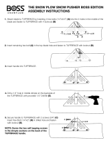
8. Plug in the motor power, motor ground, and hall
cables as shown. Note that the connectors on the
Hall and motor power cables only fit in one specific
orientation.
HALL CONNECTION
3
NOTE:
HALL CABLE PLUG HAS BUILT-IN
ALIGNMENT TAB. DO NOT FORCE
THIS PLUG.
MOTOR POWER
MOTOR GROUND
MOTOR POWER
MOTOR GROUND
HALL CONNECTION
9. Install rear VFD cover to the back of the VFD using
(4) M4-0.7 x 10mm machine screws.
NOTE: The rear VFD cover should be installed with the
“G” on the Greenheck logo closest to the motor (not
critical for fan operation).
DOWNTUBE & MOUNT ASSEMBLY
MOTOR & HUB ASSEMBLY
FRONT VFD COVER
REAR VFD COVER
M4 - 0.7 x 10 MACHINE SCREW
If networking multiple fans to run using a single control
source, the dipswitch settings on each fan’s VFD circuit
board will need to be adjusted using the following
instructions.
DIPSWITCH 3
DIPSWITCH 2
First Fan
1. Determine the first fan in the network daisy-chain
by identifying the fan that is connected directly to
the control source.
2. Remove the front VFD cover from the first fan in the
network using a phillips screwdriver.
3. Dipswitch 2 is used to set parameters that improve
network function. Verify that each of the switches
on dipswitch 2 are set as follows:
Position 1 – Off
Position 2 – On
Position 3 – On
4. Dipswitch 3 is used to set unique Modbus
addresses for each fan in the daisy-chain. Adjust
positions 1-5 on dipswitch 3 to set the desired
Modbus address. A table with all possible Modbus
addresses is shown to the right.
IMPORTANT: Positions 6 – 8 are used to set parameters
needed for fan operation and should not be adjusted.
5. Refer to instruction manual provided with HVLS
control to determine if additional networking
modifications are required. Follow instructions to
complete necessary modifications.
6. Reinstall the front VFD cover.
All Remaining Fans
1. Remove the front VFD cover using a phillips
screwdriver.
2. Set dipswitch 2 as shown below. Dipswitch 2 is
used to set parameters that improve network
function and will need to be adjusted for all fans in
the network except for the first fan.
Position 1 – Off
Position 2 – Off
Position 3 – Off
3. Adjust positions 1 – 5 on dipswitch 3 so that each
successive fan has a unique Modbus address. A
table with all possible Modbus addresses is shown
on the following page.
IMPORTANT: Positions 6 – 8 are used to set parameters
needed for fan operation and should not be adjusted.
NOTE: It is good practice to use successive Modbus
addresses for networked fans, but this is not necessary
for proper functioning of the network.
4. Refer to instruction manual provided with HVLS
control to determine if additional networking
modifications are required. Follow instructions to
complete necessary modifications.
5. Reinstall the front VFD cover.
Fan Networking

High Volume, Low Speed Ceiling Fans12
®
Safety Retention Cable Installation
IMPORTANT: Do not put excessive tension on the
safety retention cable during installation. The safety
retention cable should be installed with a small amount
of slack in the cable to ensure proper functioning. Do
not allow the safety retention cable to contact any sharp
edges.
NOTE: Failure to install the safety retention cable will
result in voiding of the fan warranty.
Standard Steel Cable Clamp
The following instructions apply to standard fan
installations. For fans that were supplied with optional
Gripple
®
hardware, refer to the instructions on page 13.
Components required from Bag # 916290:
• U-Bolt Steel Cable Clamp (2)
Hardware/Tools Needed (Not Included):
• Torque Wrench
• 7/16 in. Socket and Wrench
• Cable Cutters (optional)
1. From the top of the downtube, pull the safety
retention cable until it is taut inside the downtube.
2. Wrap the loose end of the safety cable around
the mounting structure. Do not allow the cable to
come in contact with any sharp edges.
3. Align the loose end of the safety cable (referred to
as the dead-end) with the length of cable that is
wrapped around the mounting structure (referred
to as the live-end).
4. Attach the dead-end of the safety cable to the live-
end using the supplied 0.188 in. u-bolt steel cable.
IMPORTANT: The first steel cable clamp must be
installed a minimum of 5-1/2 in. away from the dead-
end of the safety cable to ensure proper functioning.
IMPORTANT: Steel cable clamps are composed of two
parts: the u-bolt and the saddle. Steel cable clamps
must be installed with the u-bolt over the dead-end
of the safety retention cable and the saddle over the
live-end of the safety cable. Failure to install steel
Modbus Address Settings - Dipswitch 3
Modbus
Address
Position
1
Position
2
Position
3
Position
4
Position
5
Position
6, 7, 8
2 On Off Off Off Off
Do Not
Modify
3 Off On Off Off Off
4 On On Off Off Off
5 Off Off On Off Off
6 On Off On Off Off
7 Off On On Off Off
8 On On On Off Off
9 Off Off Off On Off
10 On Off Off On Off
11 Off On Off On Off
12 On On Off On Off
13 Off Off On On Off
14 On Off On On Off
15 Off On On On Off
16 On On On On Off
17 Off Off Off Off On
18 On Off Off Off On
19 Off On Off Off On
20 On On Off Off On
21 Off Off On Off On
22 On Off On Off On
23 Off On On Off On
24 On On On Off On
25 Off Off Off On On
26 On Off Off On On
27 Off On Off On On
28 On On Off On On
29 Off Off On On On

High Volume, Low Speed Ceiling Fans 13
®
cable clamps in this manner may result in unsafe
operating conditions. Refer to drawing below for correct
orientation.
5. Pull the dead-end of the safety
cable through the steel cable
clamps to tighten the cable.
The cable should be pulled taut,
leaving only a small amount
of slack in the cable to ensure
proper functioning.
6. Tighten the nuts on the steel
cable clamps using a 7/16 in.
socket and torque to 54 in∙lbf
(6.10 N∙m), alternating between
nuts until reaching proper torque.
7. Cut or organize excess safety
cable to ensure it does not
interfere with fan performance.
Make sure to leave at least
5-1/2 in. of cable between the
dead-end of the cable and the
first steel cable clamp to ensure
proper functioning.
DOWNTUBE SAFETY CABLE
DOWNTUBE & MOUNT ASSEMBLY
CABLE CLAMP
CABLE CLAMP
SADDLE
CABLE CLAMP U-BOLT
DEAD END
LIVE END
TORQUE TO 54 IN∙LBF
(6.10 N∙m)
5-1/2 IN.
MIN.
Gripple
®
Hardware (Optional)
Components required from Bag # 915067:
• No. 4 Gripple
®
Connector (1)
Hardware/Tools (Not Included):
• 1/16 in. Allen Wrench (optional)
• Cable Cutters (optional)
1. From the top of the downtube, pull the safety
retention cable until the cable is taut inside the
downtube.
2. Insert the loose end of the safety cable into the No.
4 Gripple connector. Note that the cable will only
feed through the Gripple connector in one direction
(marked on the Gripple connector with an arrow).
3. Slide the No. 4 Gripple connector down the safety
cable until it is located near the opening at the top
of the downtube.
4. Wrap the loose end of the
safety cable around the
mounting structure. Do not
allow the cable to come in
contact with any sharp edges.
5. Insert the loose end of the
safety cable into the open hole
of the No. 4 Gripple connector.
Note that the cable will only feed through the
Gripple connector in one direction (marked on the
Gripple connector with an arrow).
6. Pull the loose end of the safety cable through the
Gripple connector to tighten the cable. The cable
should be pulled taut, leaving only a small amount
of slack in the cable to ensure proper functioning.
7. Cut or organize excess safety cable to ensure it
does not interfere with fan rotation.
NOTE: If necessary, the safety cable can be loosened
by inserting the long end of a 1/16 in. allen wrench into
either of the pin holes on the No. 4 Gripple connector
and pulling the cable in the opposite direction of the
arrow marked on the Gripple connector.
DOWNTUBE SAFETY CABLE
DOWNTUBE SAFETY CABLE
DOWNTUBE & MOUNT ASSEMBLY
NO. 4 GRIPPLE

High Volume, Low Speed Ceiling Fans14
®
IMPORTANT: Guy wires must be installed 45º to 60º
from vertical to ensure proper functioning.
Standard Steel Cable Clamp
Components required from Bag # 916290:
• Guy Wire Clamp Assembly (4)
• Guy Wire Clamp Bolt (4)
• Quick Link (8)
• 20 ft. Guy Wire (4)
• U-Bolt Steel Cable Clamp (8)
• Turnbuckle (4)
Hardware/Tools Needed (Not Included):
• Level
• Torque Wrench
• 7/16 in. Socket and Wrench
• 5/16 in. Socket and Wrench
• Adjustable Wrench
• Cable Cutters (optional)
1. Secure guy wire clamps to the building structure
using the guy wire clamp bolts and an adjustable
wrench. Attach guy wires to the eyelets on the guy
wire clamp assemblies using (4) supplied quick
links.
DOWNTUBE & MOUNT ASSEMBLY
UG2 GRIPPLE
®
TURNBUCKLE
GUY WIRE
GUY WIRE
GUY WIRE
GUY WIRE CLAMP ASSEMBLY
GUY WIRE CLAMP BOLT
45º to 60º
UG2 GRIPPLE
®
TURNBUCKLE
GUY WIRE ATTACHMENT RING
QUICK LINK
2. Insert the loose end of each guy wire through the
eyebolt on a turnbuckle. Turn the guy wire back
onto itself and align the loose end of the guy wire
(referred to as the dead-end) with the length of
guy wire that is attached to the building structure
(referred to as the live-end).
3. Attach the dead-end of each guy wire to the live-
end using (2) of the supplied 0.094 in. u-bolt steel
cable clamps. Loosely tighten the nuts on the steel
cable clamps, leaving enough room for the guy
wire to slide through the steel cable clamps.
IMPORTANT: The first steel cable clamp must be
installed a minimum of 5-1/2 in. away from the dead-
end of the guy wire to ensure proper functioning.
IMPORTANT: Steel cable clamps consist of two parts:
the u-bolt and the saddle. Steel cable clamps must be
installed with the u-bolt over the dead-end of the guy
wire and the saddle over the live-end of the guy wire.
Failure to install steel cable clamps in this manner may
result in unsafe operating conditions. Refer to drawing
below for correct orientation.
DOWNTUBE & MOUNT
ASSEMBLY
GUY WIRE
45º to 60º
TURNBUCKLE
GUY WIRE
ATTACHMENT RING
CABLE CLAMP
QUICK LINK
5-1/2 IN.
MIN.
TORQUE TO 54 IN∙LBF
(6.10 N∙m)
DEAD END
LIVE END
4. Attach all (4) turnbuckles to the guy wire
attachment ring located on the downtube using
(4)supplied quick links.
5. Pull the dead-end of each guy wire through the
steel cable clamps until taut.
6. Tighten the nuts on the steel cable clamps using a
7/16 in. socket and torque to 54 in∙lbf (6.10 N∙m),
alternating between nuts until reaching proper
torque.
7. Place a level against the downtube and tighten all
(4) turnbuckles by hand in a crisscross pattern until
the guy wires are tight and the fan is level.
NOTE: When leveling the fan, place the level against
the downtube in-between two neighboring guy wires
to simplify the leveling process. The level should also
be moved around the circumference of the downtube
periodically to ensure that the fan is level in all
directions.
8. Cut or organize excess guy wires to ensure that
they do not interfere with fan performance. Make
sure to leave at least 5-1/2 in. of wire between the
dead-end of the guy wire and the first wire rope
clip to ensure proper functioning.
Guy Wire Installation

High Volume, Low Speed Ceiling Fans 15
®
Gripple
®
Hardware (Optional)
IMPORTANT: Guy wires must be installed 45º to 60º
from vertical to ensure proper functioning.
Components required from Bag # 915067:
• Guy Wire Clamp Assembly (4)
• Guy Wire Clamp Bolt (4)
• Quick Link (8)
• 20 ft. Guy Wire (4)
• No. 4 Gripple
®
Connector (4)
• Turnbuckle (4)
Hardware/Tools Needed (Not Included):
• Adjustable Wrench
• Level
• 1/16 in. Allen Wrench (optional)
1. Secure guy wire clamps to the building structure
using the guy wire clamp bolts. Attach guy wires
to the eyelets on the guy wire clamp assemblies
using (4) supplied quick links.
DOWNTUBE & MOUNT ASSEMBLY
UG2 GRIPPLE
®
TURNBUCKLE
GUY WIRE
GUY WIRE
GUY WIRE
GUY WIRE CLAMP ASSEMBLY
GUY WIRE CLAMP BOLT
45º to 60º
UG2 GRIPPLE
®
TURNBUCKLE
GUY WIRE ATTACHMENT RING
QUICK LINK
2. Insert the loose end of each guy wire into a No. 4
Gripple connector until a length of wire is pushed
through the connector. Insert the loose end of the
guy wire through the end of the turnbuckle and
push back through the No. 4 Gripple connector to
close the loop.
3. Attach all (4) turnbuckles to the guy wire
attachment ring located on the downtube using
(4) supplied quick links. Pull the loose end of each
guy wire through the No. 4 Gripple connector until
each guy wire is taut.
DOWNTUBE & MOUNT ASSEMBLY
GUY WIRE
GUY WIRE
GUY WIRE CLAMP ASSEMBLY
GUY WIRE CLAMP BOLT
45º to 60º
No. 4 GRIPPLE CONNECTOR
GUY WIRE ATTACHMENT RING
QUICK LINK
TURNBUCKLE
QUICK LINK
4. Place a level against the downtube and tighten all
(4) turnbuckles by hand in a crisscross pattern until
the guy wires are tight and the fan is level.
NOTE: When leveling the fan, place the level against
the downtube in-between two neighboring guy wires
to simplify the leveling process. The level should also
be moved around the circumference of the downtube
periodically to ensure that the fan is level in all
directions.
5. Cut or organize excess guy wires to ensure that
they do not interfere with fan rotation.
NOTE: If necessary, the guy wires can be loosened by
inserting the long end of a 1/16 in. allen wrench into
either of the pin holes on the No. 4 Gripple connector
and pulling the cable in the opposite direction of the
arrow marked on the Gripple connector.
IMPORTANT: Do not operate fans without the airfoil
blades. Failure to comply with this warning will result
in voiding of the product warranty and may result in
permanent damage to the VFD and motor.
WARNING
To reduce the risk of personal injury, do not bend
motor struts, airfoil blades, or airfoil retaining links
when installing the airfoil blades, balancing the blades,
or cleaning the fan. Damage to these components may
result in unsafe operation of the fan, which can lead
to property damage, personal injury or death. Contact
your local representative or the factory if replacement
parts are needed.
WARNING
To reduce the risk of personal injury, do not insert
foreign objects in between rotating fan blades.
AVERTISSEMENT
Pour réduire le risque de blessure, ne pliez pas les
entretoises moteurs, ailerons ou aile en conservant
des liens lors de l’installation des aubes, équilibrez,
ou nettoyer le ventilateur. Ces composants peuvent
endommager en utilisation dangereuse du ventilateur,
qui peut conduire à des dommages matériels, des
blessures ou la mort. Ces composants peuvent
endommager en utilisation dangereuse du ventilateur,
qui peut conduire à des dommages matériels, des
blessures ou la mort.
AVERTISSEMENT
Ces composants peuvent endommager en utilisation
dangereuse du ventilateur, qui peut conduire à des
dommages matériels, des blessures ou la mort.
Airfoil Blade & Winglet Installation

High Volume, Low Speed Ceiling Fans16
®
Components required from Bag # 915066 OR 854832:
• Airfoil Blade (3 OR 6)
• Winglet (3 OR 6)
• #10 – 12 x 3/4 in. Screw (6 OR 12)
• 5/16 in. Washers (12 OR 24)
• 5/16 in. – 18 Grade 8 Nylon Locknut (6 OR 12)
• 5/16 in. – 18 x 2 in. Grade 8 Hex Bolt (6 OR 12)
Hardware/Tools Needed (Not Included):
• 1/2 in. Socket and Socket Wrench
• 1/2 in. Wrench
• Torque Wrench
• #2 Phillips Bit and Driver
1. Install one winglet per airfoil blade using the screw
bosses located in each blade on the opposite end
from the mounting holes. Use a #2 phillips bit to
install (2) #10 – 12 x 3/4 in. screws per winglet.
Torque screws to 60 in∙lbf (6.8 N∙m).
AIRFOIL BLADE
SCREW BOSSES
WINGLET
#10 - 12 x 3/4 in. SCREW
(2 PER BLADE)
NOTE: Improperly fastened winglets may result in
unwanted noise.
2. Lift the first blade into place, and slide over the
motor strut allowing the airfoil retaining ring to rest
on top of the airfoil blade. It might be necessary to
use two people for this step.
5/16 in. WASHER
(2 PER BLADE)
5/16 in. - 18 GRADE 8 NYLON LOCKNUT
(2 PER BLADE)
MOTOR & HUB ASSEMBLY
5/16 in. - 18 x 2 GRADE 8 HEX BOLT
(2 PER BLADE)
MOTOR STRUT
AIRFOIL BLADE
AIRFOIL RETAINING RING SHIM
AIRFOIL BLADE
AIRFOIL RETAINING RING
AIRFOIL RETAINING RING
3. With the blade in position on the motor strut, install
(2) 5/16 in. 18 x 2 in. hex bolts, (4) 5/16 in. washers,
and (2) 5/16 in. – 18 nylon locknuts per blade as
shown below. Hand tighten hardware.
5/16 in. WASHER
(2 PER BLADE)
5/16 in. - 18 GRADE 8 NYLON LOCKNUT
(2 PER BLADE)
MOTOR & HUB ASSEMBLY
5/16 in. - 18 x 2 in. GRADE 8 HEX BOLT
(2 PER BLADE)
MOTOR STRUT
AIRFOIL BLADE
AIRFOIL BLADE
AIRFOIL RETAINING RING
AIRFOIL RETAINING RING
AIRFOIL RETAINING RING SHIM
4. Repeat steps 1 through 3 on remaining airfoil
blades. Torque the installed bolts to 25 ft∙lbf
(34N∙m).
5/16 in. - 18 x 2 GRADE 8 BOLT
(2 PER BLADE)
TORQUE TO 25 FT∙LBF
(34 N∙m)
IMPORTANT: If airfoils must be removed and
reinstalled for any reason, do not re-use the supplied
nylon locknuts. Re-use increases the risk of locknuts
loosening during operation, which may result in
unwanted noise and/or unsafe operation of the fan.
Contact your local representative or the factory if
replacement parts are needed.
Components required from Bag # 915066 OR 854832:
• Hub Plate (1)
• 1/4 in. – 20 x 1 in. Stainless Steel Machine Screw (4)
Hardware/Tools Needed (Not Included):
• Torque Wrench
1. Align (4) holes in the faceplate with the (4) U-nuts
on the hub retention bracket.
2. Insert (1) 1/4-20 x 1 stainless steel machine screw
per hole and hand tighten to ensure all fasteners
will engage the U-nuts.
3. Torque fasteners to 96 in∙lbf (10.8 N∙m).
HUB PLATE
U-NUT
HUB RETENTION BRACKET
1/4 - 20 x 1 in. STAINLESS STEEL MACHINE SCREW
Hub Plate Installation

High Volume, Low Speed Ceiling Fans 17
®
LED Light
Components required from Bag # 915436:
• Hub Covering Plate (1)
• LED Light Assembly (1)
• LED Light Mounting Bracket (1)
• 1/4 in. – 20 x 3/4 in. Grade 5 Hex Bolt (6)
• M10 – 1.5 x 20 in. Grade 8.8 Hex Bolt (1)
• 3/8 in. Washer (1)
Hardware/Tools Needed (Not Included):
• Torque Wrench
• 17mm Socket
• 3/8 in. Magnetic Nut Driver
• Magnetic Nut Driver Extension
• Impact Driver
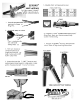
1. Use the supplied M10 – 1.5 x 20 in. grade 8.8 hex
bolt and 3/8 in. washer to attach the LED light
mounting bracket and light shroud to the light.
2. Insert the LED light mounting bracket into the
cut-out of the hub covering plate. Allow the hub
covering plate to sit on the top of the LED light
assembly.
3. Lift the LED light assembly and hub covering plate
until the u-nuts on the LED light mounting bracket
are aligned with the mounting holes in the hub
retention bracket. Install (2) 1/4 in. – 20 x 3/4 in.
grade 5 hex bolts into the u-nuts using a magnetic
nut driver extension and impact driver. Torque to
120 in∙lbf (13.6 N∙m).
4. Connect the male light
power (3 pin) and light
communication (2 pin) plugs
from the LED light assembly
to their corresponding female
connectors in the motor.
NOTE: The LED light assembly can be pivoted out of
the way to simplify connection of the light power and
light communication plugs.
5. Raise the hub covering plate until the holes in
the plate are aligned with the u-nuts on the hub
retention bracket. Install (4) 1/4 in. – 20 x 3/4 in.
grade 5 hex bolts into the u-nuts. Torque to
96 in∙lbf (10.8 N∙m).
LIGHT POWER PLUG
HUB COVERING
PLATE
HUB RETENTION
BRACKET
U-NUT
LIGHT BRACKET
LIGHT POWER PLUG
LED LIGHT ASSEMBLY
LIGHT COMMUNICATION PLUG
U-NUT
1/4 in. - 20 x 3/4 in. GRADE 5 HEX BOLT
(6 PER ASSEMBLY)
LIGHT COMMUNICATION PLUG
1/4 in. - 20 x 3/4 in. GRADE 5 HEX BOLT
M10 - 1-1/2 x 20 in. GRADE 8 HEX BOLT
3/8 in. WASHER
6. Using the attached 115v light power cable located
at the top of the downtube, wire the LED light
into the buildings light grid. Be sure to follow all
national and local codes for electrical installation.
Light Relay
Components required (included):
• Light relay Kit for HVLS control
Hardware/Tools (Not Included):
• Standard Screwdriver
• Wire Strippers
1. Land the white 0-10 input wire to the relay from the
drive of the fan.
2. Using the wiring diagram below, land the line and
neutral input power to the relay along with running
line and neutral output power to the light kit.
LIGHT RELAY
+ TO LIGHT (BROWN)
- TO LIGHT (BLUE)BLACK (LINE)
WHITE (N)
0-10V (+) (BLUE)
0-10V (-) (WHITE)
POWER SOURCE
L1
L2/N
GROUND
LIGHT POWER
BLACK (LINE)
WHITE (N)
LIGHT CONTROL
RED (0-10V)
BLACK (GROUND)
GREEN (GROUND)
LED Light Installation (Optional)
LIGHT POWER PLUG
HUB COVERING
PLATE
HUB RETENTION
BRACKET
U-NUT
LIGHT BRACKET
LIGHT POWER PLUG
LED LIGHT ASSEMBLY
LIGHT COMMUNICATION PLUG
U-NUT
1/4 in. - 20 x 3/4 GRADE 5 HEX BOLT
(6 PER ASSEMBLY)
LIGHT COMMUNICATION PLUG
1/4 in. - 20 x 3/4 GRADE 5 HEX BOLT
M10 - 1-1/2 x 20 GRADE 8 HEX BOLT
3/8 in. WASHER

High Volume, Low Speed Ceiling Fans18
®
Fire Alarm Relay Installation
The following instructions apply to fans that were
supplied with plug-and-play factory wiring.
DANGER
Always disconnect, lock and tag power source before
installing or servicing. Failure to disconnect power
source can result in fire, shock or serious injury.
DANGER
Pour écarter les risques d’incendie, de choc électrique
ou de blessure grave, veiller à toujours débrancher,
verrouiller et étiqueter la source de courant avant
l’installation ou l’entretien.
NOTE: The following instructions are only applicable
to buildings that are equipped with a fire suppression
system. If the building does not contain a fire
suppression system, leave the crimp connector on
the fire alarm landing point (located at the top of the
downtube) and continue with the rest of the installation.
IMPORTANT: The fire alarm relay should only be
installed by qualified personnel who are familiar with
the operation of building fire suppression systems. It is
the sole responsibility of the installer to ensure correct
operation of the fire alarm relay in the event of a fire
emergency in the building.
Included Component:
• Low Voltage (24VDC/VAC or 115VAC), Normally
Closed Relay (1)
Hardware/Tools Needed (Not Included):
• Standard Screwdriver
• Cable Cutters
• Wire Strippers
1. If the building is equipped with a fire suppression
system, remove the crimp connector from the fire
alarm emergency stop landing point located at the
top of the downtube by snipping the wires directly
below the crimp connector.
2. Strip the loose wires and wire the supplied
normally-closed relay to the fire alarm emergency
stop landing point and the building’s fire
suppression system using the wiring diagram
shown.
TO FIRE SUPPRESSION SYSTEM
TO LANDING POINT AT FAN
N.C.
RELAY
PRE-WIRED FIRE
ALARM LANDING POINT
WIRING BY OTHERS
Communication Wiring & Fan Control
Installation
IMPORTANT: DS fans must be installed with the
supplied CAT-5e communication cable or
shielded CAT-5e (by others) that complies with
the following specifications. Cable must be
twisted pair, shielded 26 ga. CAT-5e cable with a
drain wire and must be compliant with ISO
11801. Cable must use shielded RJ45
connectors with a soldered drain and wiring
configuration must follow EIA/TIA T568B wiring
pinout. Individual CAT-5e cable lengths must not
exceed 200 ft. in order to prevent network
communication issues.
With Pre-Built CAT-5e Cable
Included Component:
• 100 – 200 ft. CAT-5e Control Cable (1)
Hardware/Tools Needed (Not Included):
• Fan Control (1, optional)
1. Plug one end of the CAT-5e control cable into
the 2-way RJ45 splitter located at the top of the
downtube. The cable can be plugged into any
open receptacle on the splitter.
2. Identify the desired location for installation of the
fan control and run the remainder of the CAT-5e
control cable to this location.
3. Secure the CAT-5e control cable to the building
structure to ensure it does not interfere with fan
performance. To prevent communication issues, do
not coil excess control cable or route control cable
with power wiring.
4. If provided, mount the optional fan control in the
desired location and plug the CAT-5e cable into
the RJ45 port on the control. Otherwise, install
and wire the control source according to the
manufacturer’s instructions.
5. If one control source will be used to operate
multiple fans, the fans can be daisy-chained
together to create a network using the following
instructions.
FAN 1
CONTROL
FAN 2
a. Wire the first fan in the chain to the control
source using steps 1-4 above.
b. Plug an additional CAT-5e control cable into the
2-way RJ45 splitter located at the top of the
downtube on the first fan. Connect the other
end of this CAT-5e cable into the 2-way splitter
on the next fan.
Wiring and Electrical – Factory Wiring Installation

High Volume, Low Speed Ceiling Fans 19
®
c. Repeat step 5b. for subsequent fans until all
fans in the chain are connected in series.
d. Follow the “Fan Networking” instructions on
page 11 to complete network setup for the fans.
With Optional 1,000 ft. Bulk Spool of CAT-5e Cable
Included Component:
• 1,000 ft. Bulk Spool of CAT-5e Control Cable (1)
• Shielded, Pass-Through RJ45 Connectors (25)
Hardware/Tools Needed (Not Included):
• Fan Control (1, optional)
• CAT-5e Termination Tool
1. Determine required length of CAT-5e cable run.
Unspool appropriate amount of cable and cut to
length.
IMPORTANT: Individual CAT-5e cable lengths must
not exceed 200 ft. in order to prevent network
communication issues.
2. Strip and remove 2 in. of CAT-5e cable jacket
leaving the foil shield intact.
3. Fold foil shield back over cable jacket and trim foil
so that 1/4 in. remains.
4. Untwist conductor pairs, straighten and align wires
according to EIA/TIA T568B wiring pinout.
1 2 3 4 5 6 7 8
1. White/Orange
2. Orange
3. White/Green
4. Blue
5. White/Blue
6. Green
7. White/Brown
8. Brown
Foil Shield
5. Trim conductor ends flush leaving 1 in. exposed.
6. Fully insert cable into shielded, pass-through RJ45
connectors until foil enters back end of connector.
Use only the provided RJ45 connectors.
7. Verify that conductors are in the correct wiring
scheme order.
8. Crimp RJ45 connector with CAT-5e termination tool
(not included).
9. Repeat on opposite end of CAT-5e cable to
complete cable construction.
10. Follow the “With Pre-Built CAT-5e Cable”
instructions on page 18 to complete
communication wiring and fan control installation.
Power Wiring Installation
DANGER
Always disconnect, lock and tag power source before
installing or servicing. Failure to disconnect power
source can result in fire, shock or serious injury.
DANGER
Pour écarter les risques d’incendie, de choc électrique
ou de blessure grave, veiller à toujours débrancher,
verrouiller et étiqueter la source de courant avant
l’installation ou l’entretien.
IMPORTANT: Do not connect power until mechanical
installation, fire alarm relay installation, communication
wiring and fan control installation are complete.
IMPORTANT: Do not apply power to the fan above
the rated voltage of the variable frequency drive (VFD).
Failure to comply with this warning will result in voiding
of the product warranty and may result in permanent
damage to the VFD and motor.
IMPORTANT: To prevent electrical failures, source
power must comply with the following power quality
requirements. If source power falls outside of these
specified tolerances, an external power line filter will be
required (by others). If other power quality issues are
present, contact the factory for support.
Allowable Voltage
Fluctuation
+/- 10% of nominal
Allowable Frequency
Fluctuation
+/- 5% of nominal (47-63 Hz)
Area of Use
Do not install fans in electrical environments
with Pollution higher than Degree 2 in
accordance with UL 61800-5-1
Surge Immunity
Do not install fans in electrical environments
above Installation Class 3 in accordance
with IEC 61000-4-5
Hardware/Tools Needed (Not Included):
• Phillips Screwdriver
With Optional Electrical Plug
1. If the fan is supplied with the optional electrical
plug for power wiring, refer to the chart below for
the corresponding receptacle that will be needed
(provided by others).
Electrical Plug Reference (Locking)
Voltage Phase Plug* Receptacle
208-230 1 L6-30P L6-30R
277 1 L7-30P L7-30R
208-230 3 L15-30P L15-30R
460 3 L16-30P L16-30R
*NOTE: Plugs are available from manufacturer. Receptacles must be
provided by others.
2. Install the receptacle according to all national and
local codes for electrical wiring.

High Volume, Low Speed Ceiling Fans20
®
3. Insert the electrical plug into the receptacle and
twist to lock the plug in place.
4. Secure any loose power cable to the building
structure to ensure it does not interfere with fan
performance.
Without Optional Electrical Plug
1. If the fan is not supplied with the optional electrical
plug, refer to the wiring diagrams below to
complete power wiring.
2. Secure any loose power cable to the building
structure to ensure it does not interfere with fan
performance.
POWER CABLE FROM FAN
POWER CABLE FROM FAN
SINGLE PHASE (LOW VOLTAGE 208-277V)
THREE PHASE (LOW VOLTAGE 208-230V, HIGH VOLTAGE 460V)
SOURCE POWERSOURCE POWER
GROUND GROUND
GROUND GROUND
L1L1
L1 L1
L2L2
L2/NL2/N
L3 L3
Disconnect and Fuse Installation
1. If provided, mount and wire the optional safety
disconnect switch outside of the sweep of the fan’s
airfoil blades. Installation should be completed per
the disconnect manufacturer’s recommendation.
Be sure to follow all national and local codes for
electrical installation.
2. If fusing is required, refer to the fuse sizing chart.
If the fan was supplied with the optional fused
disconnect, the fuses received will match the
models shown. Install fuses per the manufacturer’s
recommendation. Be sure to follow all national and
local codes for electrical installation.
Fuse Sizing Chart
DS-3 (8 to 24 ft.) & DS-6 (8 to 18 ft.)
500W Motor
Motor Voltage 208-230V/
1,3 PH/60 HZ
277V/
1 PH/60 HZ
460V/
3 PH/60 HZ
Motor Full Load Amps
(FLA)*
7A 7A 2.5A
Fuse Required** FRN-R-10 FRS-R-10 FRS-R-5
DS-6 (20 and 24 ft.)
1100W Motor
Motor Voltage 208-230V/
1,3 PH/60 HZ
277V/
1 PH/60 HZ
460V/
3 PH/60 HZ
Motor Full Load Amps
(FLA)*
12A 12A 3.3A
Fuse Required** FRN-R-15 FRS-R-15 FRS-R-5
*FLA is based on worst case system conditions assuming lowest
nominal voltage and phase.
** Fuses shown are available as an optional accessory. Fuses
provided by others must meet requirements of all national and local
codes.
1. Disconnect and lock-out all power switches to fan.
2. Check all fasteners on the ceiling mount, mounting
kit, blades, VFD, motor and accessories for
tightness.
3. Rotate the fan impeller by hand to ensure that it
rotates freely and does not come into contact with
any obstructions.
4. Check all electrical connections for proper
attachment.
5. Verify that the fan is hanging so that the airfoils
and downtube are level and the fan is plumb to
the floor. Adjust guy wire tension as necessary (if
applicable).
Pre-Start-Up Checks
/