Page is loading ...

200753_2
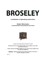
Installation & Operating Instructions
For Gas Q5 Stoves
IGNITE 5 GAS STOVE – (CD1)
HEREFORD 5 GAS STOVE – (CD2)
DESIRE 5 GAS STOVE – (SD1)
Remote or Manual Control
Conventional, Top or Rear Flue, Natural Gas Stove
PLEASE LEAVE THESE INSTRUCTIONS WITH THE END USER
Please note: Gas installations MUST only be carried out by installers who
are Gas Safe registered.
Warning - Appliance should not be used if the glass in the door is
cracked, damaged or broken.

200753_2 2
Contents
Introduction 3
Packing List 3
Specification 4
Dimensions 4
Hearth Requirements 5
Chimney Requirements 6
Assembly
Burner Installation 7
Mica Board Installation 8
Fitting the Decorative Log Retainer 9
Connecting the TTB Sensor 9
Ceramics Index 10-12
Positioning the logs 13-20
Gas Connection & Pressure Testing 21
Spillage Testing 22
Maintenance 23
Operating the Stove Manual Control Version 24
Operating the Stove Remote Control Version with Display 25-34
Cleaning the Stove / Curing the Paint 35
Trouble-shooting 36-37
Servicing 38
Commissioning Form 39
Guarantee 40

200753_2 3
Introduction
THANK YOU FOR PURCHASING A BROSELEY GAS STOVE
Broseley Fires Ltd, a family run company, was founded as an appliance and design
development company in 1975.
Since then we have built up an enviable reputation for the quality, reliability and fuel
efficiency of our stoves.
These instructions have been carefully prepared to guide the installer and end-user
through the relevant methods and standards for installation of your new Gas Stove.
Correctly installed and operated, your stove will give you many years of warmth and
reliability. Therefore, we would suggest that you read the whole instruction manual prior
to handing it to your installer. That way you will have a clearer picture of what is involved.
It is required by law that the complete assembly, installation and commissioning of gas
stoves is carried out by a professionally qualified and accredited gas fitter listed on the
“Gas Safe” register.
THE INSTALLATION MUST BE IN ACCORDANCE WITH THE ‘GAS SAFETY
INSTALLATION AND USE REGULATIONS’ IN CONJUNCTION WITH THESE
INSTRUCTIONS AND THE RELEVANT ‘BRITISH STANDARDS CODES OF
PRACTICE’ REQUIREMENTS AND THE RELEVANT ‘LOCAL AND NATIONAL
BUILDING REGULATIONS’. A COMMISSIONING CERTIFICATE MUST BE LEFT
WITH THE END CUSTOMER UPON FINAL COMPLETION AND THE
COMMISSIONING FORM COMPLETED IN THE BACK OF THESE INSTRUCTIONS.
Packing List
Stove Box Fibre Box (Packed outside Stove)
1 x Stove Body 2 x Front Rail Parts
1 x Flue Spigot 14 x Various Logs
1 x Burner (Attached) 5 x Pine Cones
1 x Instruction Manual
1 x Left hand side mica board (Attached) Remote Control Version only
1 x Right hand side mica board (Attached) 1x Remote Handset and batteries
1 x Rear mica board (Attached)
1 x Top mica board (Attached)
1 x Flue blanking plate (Attached)
3 x M6 x 30 bolts
3 x M6 Washers
3 x M6 C/Sunk Screws
1 x Metal Fuel Bed
1 X Base Plate
Chimney closure plates are not supplied

200753_2 4
Specification
Heat Input (Gross) 6.4kW
Gas Category I
2H
Supply Pressure 20 mbar
Gas Rate 0.66 m
3
/hr
Injector Size 7 x 0.73mm (Q5)
Flue diameter 125mm (5”)
Country of destination GB, IE
Efficiency Class Class 2
Nominal Output 4.6kW
NOx Class 3
Please note this product is designed to only use natural gas G20.
Dimensions
Ignite CD1 Q5 - WEIGHT 61 Kg
Hereford CD2 Q5 – WEIGHT 56 Kg
Desire SD1 Q5 – WEIGHT 58 Kg
All dimensions are in millimetres.
All parts of this appliance become hot during normal use. All parts of the appliance
should be considered ‘working surfaces’.

200753_2 5
Hearth Requirements
The appliance needs to be located onto a solid non-combustible hearth with a minimum
thickness of 12mm. The hearth must be capable of withstanding the weight of the
appliance.
NB Side measurements taken from the Lid of the stove (Dimension E on page 4):
Rear measurement taken from the dilution box
Ensure all minimum clearances to combustible materials are complied with as
below:
Hearth Protrusion (in front of the appliance) 50mm
Shelf Distance (above the stove) 300mm
The specified minimum clearances provide the minimum distance to combustible
and non-combustible materials. If the appliance is intended to be installed into a non-
combustible opening, the clearances to the sides and above can be reduced.
However it is recommended that the specific minimum clearances are maintained,
irrespective of the materials used in the construction of the opening. This has been
tested and approved, to allow adequate air flow and access to the controls, as well
as allowing access for smoke tests and future maintenance of the flue and the
appliance.
The clearance to the rear of the appliance must always be a minimum of
50mm. Clearances to combustible materials cannot be reduced
Please note the gas supply connection to the appliance is to the right hand side
rear of the stove. The connection requires an 8mm-diameter semi-rigid pipe, not
more than 1 meter in length.
Additional Requirements
Curtains should not be positioned above the appliance at a distance of less than
the minimum specified for shelves
An additional guard is to be used to take account of the special hazards that exist
in nurseries and other places where there are young children or aged or infirm
persons present.

200753_2 6
Chimney Requirements
Please note Broseley Fires do not provide flue pipes, closure plates or any other
associated accessory.
Top or Rear Flue Outlet
The stove must be installed in accordance with current gas and buildings regulations
BS5871: Part1. The appliance can be installed in any adequate area suitable for solid
fuel fires and stoves. It can use a class 1, class 2 and pre-cast flue.
For pre-cast flue installations it is ESSENTIAL that a sealed connection is made into the
actual flue system (a void behind a closure plate is not permitted). Please refer to the
codes of best practice for further advice on pre-cast flues. Before you install the stove,
make sure the chimney flue outlet is correctly positioned to align with the flue outlet on
the stove and that the chimney is in good condition. If not, a chimney liner must be
installed or a suitable class II gas flue used. A draught is necessary to ensure the
products of combustion are fully evacuated.
It is recommended that the flue run is as straight as possible. The flue must have a
minimum vertical height of 3 metres to ensure adequate draught. You can have a
maximum of four bends in the run, each bend must not exceed 45° and an
additional metre of vertical flue should be provided for each bend. Ideally you
should have a minimum vertical section of 600mm before any bend immediately
off the top of the appliance, however it is permitted to use a 45° bend straight off
the appliance provided you have an adequate flue draft.
Prior to installation, the installer should ensure that the flue is free from obstruction and
any dampers must be fixed in a permanently open position. Ensure the chimney is not
closed and that it has been swept and subsequently smoke tested.
Make sure that rain, birds or any foreign body cannot get into the chimney to cause
damage or blockage. This problem can normally be overcome by fitting an approved gas
cowl. It is essential for the effective running of your stove that the chimney draws
properly to allow the products of combustion to escape.
VENTILATION (GB ONLY)
The gas stove is rated at less than 7kw and therefore does not normally require
additional ventilation in the room (BS5871 – part II).
Flue Spigot Connection
Attach the supplied 5” diameter spigot to the top or rear of the stove using the three
M6x40 bolts and washers provided. The blanking plate (supplied) must be fitted over the
remaining flue outlet using 3 off m6 Countersunk screws.

200753_2 7
Assembly - Burner Installation
The burner will come pre-fitted, however please ensure all components are present and
fitted as per the information below prior to commencing installation. You will need a pozi
drive screwdriver when fitting/replacing these items.
1) Remove the stove body from its packaging and stand it in position.
2) To open the door, remove the handle by rotating it anti-clockwise until it clears the
thread. The handle acts like a nut on a thread and once removed will allow the door
to open fully.
3) Insert the burner end with the control knob first followed by the other end of the
burner locating the burner bracket onto the side fixing points.
4) Fasten the burner into position using two (2) M6x40 bolts and washers provided, the
burner needs to be pushed back to the rear of the stove. The front edge of the burner
brackets should be flush with the front edge of the brackets on the stove body.
5) The stove base plate can now be fitted. This plate rests on the base on the stove
6) Next fit the mica boards as detailed in the next section.

200753_2 8
Assembly – Mica Boards
First fit the rear mica board as Now fit one of the side mica boards
shown above. ensuring that the board is snug
between the front of the stove
and the rear mica
Next rest the top mica board onto Finally fit the reaming side mica
the side board (this board will board and allow the top board to
need supporting whilst the final rest down onto it (the top board
side board is fitted. should now be supported by both
the side and rear mica boards)
Please note you will also need to remove the pilot shield from the pilot
before fitting the ceramics (this protects the pilot during transit).

200753_2 9
Assembly – Decorative Log Retainer
Using the 2 off M5 C/Sunk Bolts provided, locate the decorative trim behind the stove
opening as shown and secure in position.
Assembly - Fitting TTB sensor
TTB sensor (located
just below the rear
flue outlet).
Thermo
Couple
To Gas Valve
TTB
Connection
Cable
Interrupter
Interrupter
TTB
With the burner installed, thread the TTB connection cable
from the interrupter to the TTB sensor (mounted on the rear
panel of the stove).

200753_2 10
Assembly - Positioning the Logs
Only the ceramics supplied with this appliance should be used. The ceramics should
only be laid as described in these instructions.
Before any ceramics are placed in position, ensure that the pilot is not obstructed,
and the burner is operating correctly.
Broseley Fires Ltd accepts no responsibility for any injury sustained whilst handling hot
ceramics. Ceramics which are placed other than in accordance with these instructions
will be the sole responsibility of the fitter to rectify, and Broseley Fires will not be liable
for any associated costs.
Before proceeding with the positioning of the logs, ensure they are all present. Leaving
them in the packaging will allow you to locate them easier, using this guide. Not all the
logs are stamped with a letter, so, please use the photos above to identify them.
Ceramic Index 1 of 3
C
C
B
L
B
D
B
S
S
S

200753_2 11
Assembly - Positioning the Logs
Ceramic Index 2 of 3
T
B
A
A
M
E
R

200753_2 12
Assembly - Positioning the Logs
Ceramic Index 3 of 3
Before proceeding with the positioning of the logs, ensure they are all present. Leaving
them in the packaging will allow you to locate them easier, using this guide. Not all the
logs are stamped with a letter, so, please use the photos above to identify them.
P
P
J
J

200753_2 13
Assembly - Positioning the Logs
STEP 1 - Place the metal fuel bed on top of the burner, slide backwards against the rear
mica panel, ensuring that it is located centrally left and right. The cut-out for the pilot
needs to be on the front left, as shown in the photo below.
STEP 2 - Locate the front log matrixes (2off P) between the upstands on the decorative
fret and the metal fuel bed. Ensure the ceramic is positioned as far left as possible
(ensuring the pilot is in the centre of the cut-out).
PILOT CUT-OUT
BURNER REAR
FIXING SCREWS
FRET
P
P

200753_2 14
Assembly - Positioning the Logs
STEP 3: Locate 2off curved logs (B) and 2 Logs (J) as shown below. The curved logs (B)
are to be arranged so that the left hand side log is pointing up at the rear, and the right
hand side log is pointing downwards. Both (B) logs are against the side mica panels, and
touch the rear mica board also.
The 2off logs (J) are positioned centrally behind the angled flaps on the metal fuel bed.
They are to be orientated so that the flat surface of the log, with the letter “J” impression
in it, is facing up, and is level.
Please note 2off logs (J) will appear to be upside down, but this is correct.
STEP 4 - Place straight log (B) centrally on the metal fuel bed, with the thin end pointing
backwards, resting against the front of logs (J) The large end locates into the recess
provided in the front 2 log matrixes 2off (P). Ensure that all burner ports are clear from
impingement; a small rotation counter clockwise can be done to clear ports.
J
B
B
J
B
P

200753_2 15
Assembly - Positioning the Logs
STEP 5 - Place log (R) centrally in position on top of logs (J) with the thicker end pointing
up on the LHS
STEP 6 - While holding log (R) in position place log (C) in position, ensuring that the long
finger goes into the RHS corner and the short finger lays on top of log (R) The thick end
of log (C) should sit in the recess provided in the front matrixes (P).
B
J
J
R
R
C

200753_2 16
Assembly - Positioning the Logs
STEP 7: Place the ‘Y’ shaped log, log (A) in position with the single finger resting on log
(R) and aligned centrally left to right. The two fingers of log (A) should be positioned
centrally above log (B) They will overhang the decorative fret slightly (ensure that this log
does not make contact with the glass when the door is shut)
STEP 8 - Place the second log (C) in position with the long finger resting on top of log
(R), and the short finger resting down on log (B) aligned above the opening in the metal
fuel bed. The single end of the log rests against the door opening and overhangs the fret
slightly. (ensure that this log does not make contact with the glass when the door is shut)
B
R
A
C
R
B

200753_2 17
Assembly - Positioning the Logs
STEP 9 - Place the third log (B) on top of the LHS Log (B & C) as shown in the photo
below. It sits on top of the short finger of log (C).
STEP 10 - Now place the 2x small pine cones (S) as shown below.
B
B
C
S

200753_2 18
Assembly - Positioning the Logs
STEP 11 - Place log (D) in position shown below. Log (D) rests against the rear mica
board, and sits on top of logs (R) to the right hand end, and log (A) at the left hand end.
The two protrusions are pointing downwards.
STEP 12 - Pine cone (L) is placed so it rests against the right hand mica board, and on
top of log (C). Place pine cones (S) and (M) as shown below.
D
A
R
L
C
S
M

200753_2 19
Assembly - Positioning the Logs
STEP 13 - Place log (T) in position so that the thick end is positioned in the front right
hand corner, against the side mica panel and the metal body of the stove. The other end
of log (T) rests upon the (C) log. The end of log (T) should finish in-line with the single
finger of log (A) with a small gap between them.
STEP 14 - Place the second log (A) so that the tip of the RHS fork rests on top of log (T)
and the tip of the LHS fork rests on top of log (R)
A
T
T
R
A

200753_2 20
Assembly - Positioning the Logs
STEP 15 - Log (E) sits with the thin end in the front right hand side corner, and the thick
end resting on top of log (A)
Any soot accumulation within the appliance (including visible soot on logs) indicates that
the ceramics need to be re-positioned.
It is important that flames from the burner are not impinged by any of the ceramics, small
adjustments may be necessary.
E
A
/