BX SERIES
INSTALLATION MANUAL
BX10
AUTOMATION SYSTEMS FOR SLIDING GATES
E
ng
li
s
h
E
N

4.1 Operator
4 Description
2.1 Intended use
1 Legend of symbols
This symbol tells you to read the section with particular care.
This symbol tells you that the sections concern safety issues.
This symbol tells you what to say to the end-users.
2 Conditions of use
The BX10 operator is designed to power sliding gates in residential settings.
Do not install or use unless as otherwise shown in this manual.
3 Reference standards
“IMPORTANT INSTALLATION, SAFETY INSTRUCTIONS”
“CAUTION: IMPROPER INSTALLATION MAY CAUSE SERIOUS DAMAGE, FOLLOW ALL INSTALLATION INSTRUCTIONS CAREFULLY”
“THIS MANUAL IS ONLY FOR PROFESSIONAL OR QUALIFIED INSTALLERS”
2.2 Limitations to use
This product is engineered and manufactured by CAME CANCELLI AUTOMATICI S.p.A. in compliance with current safety standards.
Guaranteed 24 months if not tampered with.
The operator is made of a cast aluminium part inside of which operates the irreversible, electromechanical gearmotor and an ABS
plastic lining which holds the electronic card and transformer
4.2 Technical features
The company CAME cancelli automatici is ISO 9001:2000 quality certified; it has also obtained the ISO 14001 environmental safe-
guarding certification. CAME engineers and manufactures all of its products in Italy.
This product complies with the following legislation: see declaration of compliance.
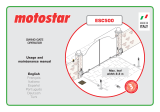
For intensive or condominium use: max gate weight 800 kg with max gate length 20 m.
BX-10 OPERATOR
Control panel power supply: 230V A.C. 50/60Hz
Operator power supply: 230V A.C.
Draw: 2.4A
Power: 300 W
Reduction ratio: 1/33
Thrust: 800 N
Max speed.: 10 m/min max.
Duty cycle: 30%
Protection rating: IP54
Insulation class: I
Motor’s thermo-protection: 150°
Weight: 15 kg
#
#
Pag.
2
2 - Manual code:
119BU57
119 B U57 ver.
0.2
0.2 02/2008 © CAME cancelli automatici s.p.a. - The data and information reported in this installation manual are susceptible to change at any time and without obligation on CAME cancelli automatici s.p.a. to notify users.
ENGLISH

4.4 Dimensions
4.3 Description of parts
(mm)
5 Installation
Installation must be carried out by expert qualified personnel and in full compliance with current regulations.
5.1 Preliminary checks
Before installing, do the following:
• Make sure that the gate is stable, and that the castors are in good working order and properly greased.
• The ground rack must be well secured to the ground, entirely above the surface and free of any irregularities that may obstruct the
gate’s movement.
• The upper guide rails must not create any friction.
• Make sure that there is a closing and an opening endstops.
• Make sure that the operator is attached to a solid surface and protected from any impacts;
• Make sure you have a suitable omnipolar cut-off device with contacts more than 3 mm apart, and independent (sectioned off) power
supply;
• Check that any connections inside the container (that provide continuity to the safety circuit) are fitted with additional insulation
compared to other internal live parts;
• Make sure you have suitable tubing and conduits for the electrical cables to pass through and be protected against mechanical
damage.
9
3
4
2
5
6
7
10
11
1 - Top cover
2 - Settings casing
3 - Control board support
4 - Endstop fins
5 - ZBX10 electronic card
6 - Front cover to control panel
7 - Gearmotor release door
8 - Securing plate
9- Securing bolt
10- Securing screw plate
11- Nut
1
2
8
Pag.
3
3 -
Manual code
:
119BU57
119 B U57
ver.
0.2
0.2 02/2008 © CAME cancelli automatici s.p.a. -
The data and information reported in this installation manual are susceptible to change at any time and without obligation on CAME cancelli automatici s.p.a. to notify users.
ENGLISH

Make sure you have all the tools and materials you will need for the installation at hand to work in total safety and compliance
with the current standards and regulations. The following figure illustrates the minimum equipment needed by the installer.
N.B.: If the cable length differs from that specified in the table, then you must determine the proper cable diameter in the basis of
the actual power draw by the connected devices and depending on the standards specified in CEI EN 60204-1.
For connections that require several, sequential loads, the sizes given on the table must be re-evaluated based on actual power
draw and distances. When connecting products that are not specified in this manual, please follow the documentation provided
with said products.
5.3 Cable list and minimum thickness
Connection Type of cable Length of cable 1 < 10 m Leng. cable 10 < 20 m Leng. cable 20 < 30 m
Control panel power supply 230V
FROR CEI
20-22
CEI EN
50267-2-1
3G x 1,5 mm
2
3G x 2,5 mm
2
3G x 4 mm
2
Flashing light 2 x 0,5 mm
2
2 x 1 mm
2
2 x 1,5 mm
2
Photocell transmitter 2 x 0,5 mm
2
2 x 0.5 mm
2
2 x 0,5 mm
2
Photocell receiver 4 x 0,5 mm
2
4 x 0,5 mm
2
4 x 0,5 mm
2
Accessories power supply 2 x 0,5 mm
2
2 x 0,5 mm
2
2 x 1 mm
2
Safety and control devices 2 x 0,5 mm
2
2 x 0,5 mm
2
2 x 0,5 mm
2
Antenna connection RG58 max. 10 m
5.2 Tools and materials
1) BX10 Assembly
2) Rack
3) Reception Antenna
4) Flashing light
5) Keyswitch selector
6) Safety photocells
7) Electric cable junction box
8) Mechanical endstops
9) Guide rails
10) Endstop fi ns
5.4 Standard installation
3
1
8
2
4
5
6
6
7
9
10
10
Pag.
4
4 - Manual code:
119BU57
119 B U57 ver.
0.2
0.2 02/2008 © CAME cancelli automatici s.p.a. - The data and information reported in this installation manual are susceptible to change at any time and without obligation on CAME cancelli automatici s.p.a. to notify users.
ENGLISH

- Dig a pit to the side of the gate (see measurements from diagram).
Prepare the corrugated tubes you will need when making connections coming from the shunt pit.
N.B. the number of tubes depends on the type of system and the accessories you will hook up.
The following applications are only examples, as the space for installing the ratiomotor and accessories varies according to
obstructions. It is thus up to the system installer to select the most suitable solution.
Shunt pit
5.5 Securing the plate and installing the assembly
Conduits for electric
cables
-Prepare the securing plate, insert the bolts into the holes and lock them using the supplied nuts and washers. Extract the preformed
brackets using a screw driver or a set of pliers.
- Position the plate on top of the grid. Careful! The tubes need to pass through the apposite holes.
- Prepare a form box that is larger in size than the securing plate and insert it into the pit. The form box should jut 50mm above
ground level.
Insert an iron grid inside the from box to reinforce the concrete.
Pag.
5
5 -
Manual code
:
119BU57
119 B U57
ver.
0.2
0.2 02/2008 © CAME cancelli automatici s.p.a. -
The data and information reported in this installation manual are susceptible to change at any time and without obligation on CAME cancelli automatici s.p.a. to notify users.
ENGLISH

H
- To position the plate in relation to the rack please see the measurements on the diagram.
Fill the form box with cement and wait for at least 24 hours for it to solidify.
- Remove the form box, fi ll the pit around the cement block with soil.
- Unbolt the nuts and washers from the bolts. The securing plate must be clean, perfectly aligned and with the bolt threads completely
on the surface.
Insert the electric cables into the tubes until they exit about 400mm.
Pag.
6
6 - Manual code:
119BU57
119 B U57 ver.
0.2
0.2 02/2008 © CAME cancelli automatici s.p.a. - The data and information reported in this installation manual are susceptible to change at any time and without obligation on CAME cancelli automatici s.p.a. to notify users.
ENGLISH

- Remove the cover from the gearmotor by loosening the side bolts, perforate the cable shafts using a screwdriver or a pair of
scissors and position the gearmotor atop the plate. Careful! The electric cables must pass through the cable shafts.
- Lift the gearmotor from the securing plate by about 5 to 10mm by using the threaded steel-levelling feet to allow any later
adjustments between the pinion and the rack.
- The following illustrations for the securing the rack, are just examples of applications. It is up to the installer to choose the best
solution.
Releasing the gearmotor (see paragraph on manual release). Rest the rack on the gearmotor pinion.
Weld or secure the rack to the gate along its entire length.
To assemble the rack modules, use an excess piece of rack and place it under the joining point, then block it using two C-clamps.
Note: if a rack is already in place, then just adjust the pinion-to-rack distance.
Pag.
7
7 -
Manual code
:
119BU57
119 B U57
ver.
0.2
0.2 02/2008 © CAME cancelli automatici s.p.a. -
The data and information reported in this installation manual are susceptible to change at any time and without obligation on CAME cancelli automatici s.p.a. to notify users.
ENGLISH

- Open and close the gate manually and register the pinion-to-rack distance using the threaded steel-levelling feet (for vertical
adjusting) and the slotted holes (horizontal adjusting). This prevents the weight of the gate from bearing on the operator.
Once adjustments are fi nished, secure the assembly using the nuts and washers.
Insert the cover after performing the adjustments and settings on the electronic card.
Levelling feet
Slotted holes
Rack
Pinion
vertical adjusting
horizontal adjusting
Rack
Pinion
Pag.
8
8 - Manual code:
119BU57
119 B U57 ver.
0.2
0.2 02/2008 © CAME cancelli automatici s.p.a. - The data and information reported in this installation manual are susceptible to change at any time and without obligation on CAME cancelli automatici s.p.a. to notify users.
ENGLISH

5.7 Manually releasing the gearmotor
- Insert the trilobed key into the lock, push it in and turn it clockwise ....
5.6 Mounting the endstop fins
Place the endstop fi ns onto the rack and secure them using a 3 mm Allen wrench. Their positioning limits the gate run.
Note: the gate schould not slam against the mechanical stop, when opening or closing.
Mechanical stop
WARNING: opening the door will
disengage the motor (i.e. it will not
function).
To operate the motor the release mecha-
nism must be fi rmly fastened.
Trilobed key
Knob
..... open the small door and turn the release handle clockwise.
Pag.
9
9 -
Manual code
:
119BU57
119 B U57
ver.
0.2
0.2 02/2008 © CAME cancelli automatici s.p.a. -
The data and information reported in this installation manual are susceptible to change at any time and without obligation on CAME cancelli automatici s.p.a. to notify users.
ENGLISH

FUSE TABLE ZBX10
To protect: fuse:
Control board (line) 3.15A-F
Accessories 1.6A-F
Command devices 1A-F
TECHNICAL INFORMATION
Power supply 230V - 50/60 Hz
Maximum power allowed 300 W
Absorption at rest 110 mA
Maximum power for 24V accessories 37 W
6 Control board
6.1 General description
6.2 Main components
14
15
11
17
12
16
6
8 8
9
Use 230V A.C. to power the electronic card using the L-N terminals, at a max 50/60Hz frequency.
Use 24V to power the command devices and accessories. Careful! The accessories cannot exceed 37W of overall power.
All connections are protected by quick-fuses – see table.
The input and output contact functions, the timing settings and users’ management, are set and viewed on the display, which is run
by software.
Warning! Before a
cting on the machinery, cut off the main power supply and disconnect any emergency batteries.
2
9
13
10 1
7
5 3
1) Display
2) Card fuse
3) Accessory fuse
4) Line fuse
5) AF card coupling for remote control
6) RSE card coupling for paired connections
7) 230V-power signalling LED
8) Connecting terminal board
9) Transformer-connecting terminal board
4
10) Programming buttons
11) Display lighting adjustment trimmer
12) Memory roll board connector
13) Power supply terminals
14) Motor terminals
15) Antenna terminals
16) Encoder terminals
17) Endstop terminals
Pag.
10
10 - Manual code:
119BU57
119 B U57 ver.
0.2
0.2 02/2008 © CAME cancelli automatici s.p.a. - The data and information reported in this installation manual are susceptible to change at any time and without obligation on CAME cancelli automatici s.p.a. to notify users.
ENGLISH

6.3 Electrical connections
230V (A.C.) motor with encoder
Closing microswitch
Gearmotor, endstop and encoder
Modifications to the electrical connections for right-hand installations
Invert the gearmotor (U-V) and (FA-FC)
endstop phases.
Opening microswitch
Description of the standard electrical connections for left-hand installations
%$&#&!&
567
#!0!#)4/2
%$&#&!&
567
#!0!#)4/2
COM
NC
NC
COM
Orange
Orange
White
Red
Black
Red
Red
Orange
White
,
.
+
-
Terminals for powering the following accessories:
- 24V A.C. Maximum allowed power: 37W
Power supply for accessories
230V (A.C.) Power, 50/60Hz
frequency
Cable lug with bolt and washer for connecting to earth.
Pag.
11
11 -
Manual code
:
119BU57
119 B U57
ver.
0.2
0.2 02/2008 © CAME cancelli automatici s.p.a. -
The data and information reported in this installation manual are susceptible to change at any time and without obligation on CAME cancelli automatici s.p.a. to notify users.
ENGLISH

Open-gate status light
(contact range: 24V – 3W max)
- Signal that gate is open; turns off when
gate is closed.
Movement fl ashing light
(Contact range: 230V – 25W max)
- Flashes during the gate’s opening and
closing phases.
Command and control devices
Warning devices
%%87
Cycle lamp: (contact rating: 230V – 60W max.).
It lights up the driving area and stays on from the
moment the gate begins to open until it is fully
closed (including the automatic closing time). If au-
tomatic closing is not activated, the lamp stays on
only during movement or for a set time of 5 minutes
if used as a courtesy lamp.
Stop button (N.C. contact) - Gate stop button. Excludes automa-
tic closing. For motion to resume, press the command button or
the remote control button.
N.B.: if contact is unused, select OFF on the “FUNCTIONS” menu.
Key selector and/or opening button (N.O. contact)
- Gate opening command.
Key selector and/or commands button (N.O. con-
tact) Commands for opening and closing the gate
– pressing the button or turning the key-switch,
inverts the gate’s movement or stops it depending
on how it is set on the 2-7 command in the “FUNC-
TIONS” menu
Key selector and/or partial opening button (N.O.
contact) - Partial gate opening for pedestrian
access.
Key selector and/or closing button (N.O. contact)
- Gate closing command.
Antenna with RG58
cable for the remote
control.
Pag.
12
12 - Manual code:
119BU57
119 B U57 ver.
0.2
0.2 02/2008 © CAME cancelli automatici s.p.a. - The data and information reported in this installation manual are susceptible to change at any time and without obligation on CAME cancelli automatici s.p.a. to notify users.
ENGLISH

Safety devices
RX
TX
Confi gure either (N.C.) contacts CX or CY, input for
safety devices such as photocells, that comply with EN
12978 standards. See CX or CY input functions in:
- C1 «re-open during closing phase», When the
gate leaf is closing, opening the contact triggers the
inversion of the direction of movement until the gate
leaf is fully open.
- C2 «re-close during opening phase», When gate
is opening, if the contact is opened it triggers an
inversion of the direction until gate is fully closed;
- C3 «partial stop», gate stops if moving and
automatically shuts (if this functions has been
selected);
- C4 «stand-by Obstacle», Halts the moving gate
leaves causing them to start moving again once
obstacle is removed.
- Deactivated, if the contact is unused.
DIR photocells
RX TX
./
#.#
DOC photocells
DF
#./.#
6 6
.#
./
#
6
#./.#
Confi gure either (N.C.) contacts C7 or C8, input
for EN 12978 compliant safety devices such as
sensitive edges. See C7 or C8 input functions in:
- C7 «re-open during closing phase», - During
gate closing, opening the contact causes
inversion of movement until gate is fully open;
- C8 «re-close during opening phase», - During
gate opening, opening the contact causes
inversion of movement until gate is fully close;
OFF, is the contact is unused
DF with DFI con-
nections monitor
card
Pag.
13
13 -
Manual code
:
119BU57
119 B U57
ver.
0.2
0.2 02/2008 © CAME cancelli automatici s.p.a. -
The data and information reported in this installation manual are susceptible to change at any time and without obligation on CAME cancelli automatici s.p.a. to notify users.
ENGLISH

6.4 Electrical connection to operate the photocells’ safety test
4
3
2
1
,4
,4
,4 ,4 #4
63
./
.#
#
&53)"),%M!
48
48
48
#
.#
(DOC)
(DIR)
At each open/close command, the card check the photocells’ effi ciency.
Any problems with the photocells will cause the (PROG) Led to fl ash on the
electronic card, which cancels any commands from the radio transmitter or
push-button.
Electrical connection to operate the photocells’ safety test:
- The transmitter and receiver, must be connected as shown in the diagram;
- from the functions menu, select “safety tests” and select either CX or CY input/s to activate the test.
6.5 Motor torque limiter
To vary the motor torque, move the shown faston (the one
with the black wire) to one of the 4 positions: 1 min – 4 max.
Pag.
14
14 - Manual code:
119BU57
119 B U57 ver.
0.2
0.2 02/2008 © CAME cancelli automatici s.p.a. - The data and information reported in this installation manual are susceptible to change at any time and without obligation on CAME cancelli automatici s.p.a. to notify users.
ENGLISH

7.1 Description of display commands
The ENTER key is for:
- entering the menu
- confirming and memorising set values
The ESC key is for:
- exiting the menu
- cancelling modifications
The <> keys are for:
- shifting from one menu item to another
- increase or decrease values
the <...> symbols on the display are for:
- pointing out the currently, selected item
7.2 Browsing the menu
To enter the menu, keep the
ENTER key pressed for at least
one second.
To select a menu
item, mode using the
greater than-lesser
than keys...
...then press ENTER
also use the greater
than-lesser than keys
for the “sub-menus”...
If the <> are on the TIME func-
tion, you may modify the value.
To increase or reduce
values, use the greater
than-lesser than keys...
...then press ENTER to con-
firm...
...to exit the menu, wait 30 se-
conds, or press ESC, until start
screen is displayed.
N.B.: when the menu is active, the system cannot be used.
7 Programming
WWW.CAME.IT
BX10
LANGUAGE
English
Þß
LANGUAGE
English
Þß
FUNCTIONS
English
Þß
TIMING ADJ.
Þß
A.C.T.
90s
Þß
Cycle Time
90s
Þß
Cycle Time
90s
Þß
Cycle Time
100s
Þß
{
{
{
{
...then press ENTER
LANGUAGE
Þß
Pag.
15
15 -
Manual code
:
119BU57
119 B U57
ver.
0.2
0.2 02/2008 © CAME cancelli automatici s.p.a. -
The data and information reported in this installation manual are susceptible to change at any time and without obligation on CAME cancelli automatici s.p.a. to notify users.
ENGLISH

7.3 Menu structure
< LANGUAGE >
<TIMING ADJ.>
<ADJUSTMENTS>
<English>
< INFO >
<Francais>
<Deutsch>
<Espanol><Italiano>
< A.C.T. >
< Cycle Time >
<Preflashing T.>
<Partial A.C.T.>
< New User >
< Modify User >
< Remove Usr. >
< Backup data >
<Restore backup>
<Delete all U sr>
<Gate run Adj >
< Slowdown >
<Slow.Down Spd.>
<Gate run sens.>
<Slowdown sens.>
< Partial op. >
< Brake Force >
< NET address >
< Starup Msg >
ENTER
< 10s >
>
ENTER
>
>
ENTER
< FUNCTIONS >
>
>
ENTER
>>
< 11s >
< 90s >
>
ENTER
>
< 91s >
< 5s >
>
ENTER
>
< 6s >
< 5s >
>
ENTER
>
< 6s >
ENTER
<2-7 Func>
>
ENTER
ENTER
<Only Open>
ENTER
ENTER
< RADIO USRS >
ENTER
Do you conf.?
< No >
>
ENTER
ENTER
ENTER
< FW Version >
ver. 1.0
>
<Manoeuvres No.>
16480
>
>
>
>
>
>
>
<Partial>
>
>
>
Reading
ooooooo
•••
Writing
ooooooo
•••
n.001 In use
>
n.002 Empty
>
ENTER
n.001 In use
>
n.002 Empty
>
>
>
>
>
See detailed descrip-
tion on page 28
>
< 10% >
>
ENTER
>
< 11% >
>
< 10% >
>
ENTER
>
< 11% >
< Disabled >
>
ENTER
< Master >
< Slave >
>
>
ENTER
WWW.CAME.IT
ZBX10
ENTER
>
>
<
-oooo+
>
•
<
-oooo+
>
•
ENTER
>
>
<
-oooooooo+
>
•
<
-oooooooo+
>
•
ENTER
>
>
<
-oooo+
>
•
<
-oooo+
>
•
ENTER
>
>
<
-ooooo+
>
•
•
•
<
-ooooo+
>
•
•
•
•
>
>
>
>
>
>
>
>
>
>
>
>
>
>
Do you conf.?
< Yes >
Pag.
16
16 - Manual code:
119BU57
119 B U57 ver.
0.2
0.2 02/2008 © CAME cancelli automatici s.p.a. - The data and information reported in this installation manual are susceptible to change at any time and without obligation on CAME cancelli automatici s.p.a. to notify users.
ENGLISH

< ON >
< OFF >
>
ENTER
>
ENTER
<Op.-Stop-Cl.>
<Open Close>
>
>
ENTER
>
>
< Disabled >
< C1 >
< C2 >
< C3 >
< C4 >
>
>>
< Disable >
<Enabled on CX>
<Enabled on CY>
<Enabled CX+CY>
< Autom.Clos. >
< 2-7 Command >
< Preflash >
<Maintained Act>
<Maint. Act. Cl.>
< CY Input >
< C7 Input >
< C8 Input >
< STOP (1) >
< Safety test >
< Lamp Output >
< CX Input >
>
< Disabled >
< Closing >
< Op. + Cl. >
< O p .+ Cl.+ Sto p >
< Brake >
< ON >
< OFF >
>
ENTER
>
< ON >
< OFF >
>
ENTER
>
< ON >
< OFF >
>
ENTER
>
ENTER
>
>
< Disabled >
< C1 >
< C2 >
< C3 >
< C4 >
>
>>
< ON >
< OFF >
>
ENTER
>
< ON >
< OFF >
>
ENTER
>
< ON >
< OFF >
>
ENTER
>
ENTER
>
>
>
>
ENTER
>
>
< Cycle >
< Courtesy >
ENTER
>
>
>
>
>
>
>
>
>
>
>
>
>
>
>
>
< Obst. Detect >
< ON >
< OFF >
>
ENTER
>
>
Pag.
17
17 -
Manual code
:
119BU57
119 B U57
ver.
0.2
0.2 02/2008 © CAME cancelli automatici s.p.a. -
The data and information reported in this installation manual are susceptible to change at any time and without obligation on CAME cancelli automatici s.p.a. to notify users.
ENGLISH

7.3 Main menu
LANGUAGE
English
FUNCTIONS TIMING ADJ.
RADIO USRSADJUSTMENTS
INFO
Press ENTER for
1 second
7.4 Language menu
Select language: selects among the languages displayed.
< LANGUAGE >
English
LANGUAGE
< English >
LANGUAGE
< Francais >
LANGUAGE
< Deutsch >
LANGUAGE
< Espanol >
LANGUAGE
< Italiano >
FUNCTIONS
FUNCTIONS
TIMING ADJ.
IMING ADJ
RADIO USRS
ADIO USRS
ADJUSTMENTS
DJUSTMENT
7.5 Functions menu
< Autom.Clos. >
ON
Autom.Clos.
< ON >
Autom.Clos.
< OFF >
Automatic Closing: activates or deactivates the automatic closing function.
The automatic closing timer activates at each opening endpoint. The predetermined time may be adjusted, and is in any case
dependent on any safety devices that may activate; and it does not activate after a total safety “stop” or during a power outage.
2-7 Command: sets the sequential command.
“Open-close” or “open-stop-close-stop” function with button [2-7] and radio transmitter (when radio-frequency card is inserted)
< 2-7 Command >
Op.-Stop-Cl.
2-7 Command
< Op.-Stop-Cl. >
2-7 Command
< Open Close >
X 2
X 2
INFO
INFO
<
LANGUAGE
>
English
h
FUNCTIONS
TIMING ADJ.
TIMING AD
RADIO USRS
RADIO USR
ADJUSTMENTS
DJUSTMEN
INFO
INFO
<
LANGUAGE
>
English
h
FUNCTIONS
TIMING ADJ.
TIMING AD
RADIO USRS
RADIO USR
ADJUSTMENTS
DJUSTMEN
INFO
INFO
Pag.
18
18 - Manual code:
119BU57
119 B U57 ver.
0.2
0.2 02/2008 © CAME cancelli automatici s.p.a. - The data and information reported in this installation manual are susceptible to change at any time and without obligation on CAME cancelli automatici s.p.a. to notify users.
ENGLISH

X 2
Pre-flashing: after an opening or closing command, the fl ashing light, connected to W-E1, starts fl ashing before the gate begins its
run (to set the time, see “Pre-fl ashing timing” from the Adjust Timings menu
X 2
< Preflash >
OFF
Preflash
< OFF >
Preflash
< ON >
Maintained action: The gate works by keeping the button pressed (button 2-3 for opening, button 2-4 for closing, or if set to the “On
Closing” function, only with button 2-4.
Closing maintained action: the gate closes by keeping the button pressed (only for the 2-4 closing button).
X 2
CX input: N.C. safety contact input, lets you pair up the following functions: C1 (re-opening during closing), C2 (re-closing during ope-
ning), C3 (partial stop), C4 (obstacle stall), or, deactivated
< CX Input >
Disabled
CX Input
< Disabled >
CX Input
< C1 >
CX Input
< C2 >
CX Input
< C3 >
CX Input
< C4 >
X 2
X 3
Maintained Act
< OFF >
<M aintained Act>
OFF
Maintained Act
< ON >
X 2
X 4
Maint.Act. Cl.
< OFF >
< Maint.Act. Cl. >
OFF
Maint.Act. Cl.
< ON >
X 5
<
LANGUAGE
>
English
h
FUNCTIONS
TIMING ADJ.
TIMING AD
RADIO USRS
RADIO USR
ADJUSTMENTS
DJUSTMEN
INFO
INFO
<
L
ANGUAGE >
English
h
FUNCTIONS
TIMING ADJ.
TIMING AD
RADIO USRS
RADIO USR
ADJUSTMENTS
DJUSTMEN
INFO
INFO
<
LANGUAGE
>
English
h
FUNCTIONS
TIMING ADJ.
TIMING AD
RADIO USRS
RADIO USR
ADJUSTMENTS
DJUSTMEN
INFO
INFO
<
LANGUAGE
>
English
h
FUNCTIONS
TIMING ADJ.
TIMING AD
RADIO USRS
RADIO USR
ADJUSTMENTS
DJUSTMEN
INFO
INFO
Pag.
19
19 -
Manual code
:
119BU57
119 B U57
ver.
0.2
0.2 02/2008 © CAME cancelli automatici s.p.a. -
The data and information reported in this installation manual are susceptible to change at any time and without obligation on CAME cancelli automatici s.p.a. to notify users.
ENGLISH

X 2
X 8
CY input: N.C. safety contact input, lets you pair up the following functions: C1 (re-opening during closing), C2 (re-closing during ope-
ning), C3 (partial stop), C4 (obstacle stall), or, deactivated
C7 input: N.C. safety contact input (re-opening when closing). This input is for EN 12978-compliant safety devices, like sensitive edges.
When the gate is closing, the open contact triggers an inversion in the gate’s movement until it is fully opened.
C8 input: N.C. safety contact input (re-closing during opening). This input is for EN 12978-compliant safety devices, like sensitive
edges. When the gate is opening, the open contact triggers an inversion in the gate’s movement until it is fully closed.
C8 Input
< OFF >
< C8 Input >
OFF
C8 Input
< ON >
STOP (1): this function stops the gate and consequently excludes any automatic closing cycle; for movement to resume, you need
to use the keypad or transmitter. Insert safety device on [1-2]; is unused, select “OFF” and confirm with ENTER.
X 2
X 6
< CY Input >
Disabled
CY Input
< Disabled >
CY Input
< C1 >
CY Input
< C2 >
CY Input
< C3 >
CY Input
< C4 >
X 2
X 7
C7 Input
< OFF >
< C7 Input >
OFF
C7 Input
< ON >
X 2
X 9
STOP (1)
< ON >
< STOP (1) >
OFF
STOP (1)
< OFF >
<
LANGUAGE
>
English
h
FUNCTIONS
TIMING ADJ.
TIMING AD
RADIO USRS
RADIO USR
ADJUSTMENTS
DJUSTMEN
INFO
INFO
<
LANGUAGE
>
English
h
FUNCTIONS
TIMING ADJ.
TIMING AD
RADIO USRS
RADIO USR
ADJUSTMENTS
DJUSTMEN
INFO
INFO
<
LANGUAGE
>
English
h
FUNCTIONS
TIMING ADJ.
TIMING AD
RADIO USRS
RADIO USR
ADJUSTMENTS
DJUSTMEN
INFO
INFO
<
LANGUAGE
>
English
h
FUNCTIONS
TIMING ADJ.
TIMING AD
RADIO USRS
RADIO USR
ADJUSTMENTS
DJUSTMEN
INFO
INFO
Pag.
20
20 - Manual code:
119BU57
119 B U57 ver.
0.2
0.2 02/2008 © CAME cancelli automatici s.p.a. - The data and information reported in this installation manual are susceptible to change at any time and without obligation on CAME cancelli automatici s.p.a. to notify users.
ENGLISH
Page is loading ...
Page is loading ...
Page is loading ...
Page is loading ...
Page is loading ...
Page is loading ...
Page is loading ...
Page is loading ...
Page is loading ...
Page is loading ...
Page is loading ...
Page is loading ...
Page is loading ...
Page is loading ...
/