Page is loading ...

BX SERIES
INSTALLATION MANUAL
BX-246
AUTOMATION SYSTEMS FOR SLIDING GATES
E
ng
li
s
h
EN

4.1 Operator
4 Description
2.1 Intended use
1 Legend of symbols
This symbol tells you to read the section with particular care.
This symbol tells you that the sections concern safety issues.
This symbol tells you what to say to the end-users.
2 Conditions of use
The BX246 operator is designed to power sliding gates in residential and condominium settings.
Do not install or use unless as otherwise shown in this manual.
3 Reference standards
“IMPORTANT INSTALLATION, SAFETY INSTRUCTIONS”
“CAUTION: IMPROPER INSTALLATION MAY CAUSE SERIOUS DAMAGE, FOLLOW ALL INSTALLATION INSTRUCTIONS CAREFULLY”
“THIS MANUAL IS ONLY FOR PROFESSIONAL OR QUALIFIED INSTALLERS”
2.2 Limitations to use
This product is engineered and manufactured by CAME CANCELLI AUTOMATICI S.p.A. in compliance with current safety standards.
Guaranteed 24 months if not tampered with.
The operator is made of a cast aluminium part inside of which operates the irreversible, electromechanical gearmotor and an ABS
plastic lining which holds the electronic card, transformer and the clamp to house 2 emergency batteries.
4.2 Technical features
The company CAME cancelli automatici is ISO 9001:2000 quality certified; it has also obtained the ISO 14001 environmental safe-
guarding certification. CAME engineers and manufactures all of its products in Italy.
This product complies with the following legislation: see declaration of compliance.
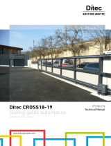
For intensive or condominium use: max gate weight 600kg with max gate length 18 m.
BX246 OPERATOR
Control panel power supply: 230V A.C. 50/60Hz
Operator power supply: 24V D.C.
Draw: 10 A
Power: 400 W
Reduction ratio: 1/33
Thrust: 700 N
Max speed.: 10 m/min max.
Duty cycle: intensive use
Protection rating: IP54
Insulation class: I
Weight: 15 kg
#
#
Pag.
2
2 - Manual code:
119BU50
119 B U 50 ver.
1.0
1.0 10/2007 © CAME cancelli automatici s.p.a. - The data and information reported in this installation manual are susceptible to change at any time and without obligation on CAME cancelli automatici s.p.a. to notify users.
ENGLISH

4.4 Dimensions
4.3 Description of parts
(mm)
5 Installation
Installation must be carried out by expert qualified personnel and in full compliance with current regulations.
5.1 Preliminary checks
Before installing, do the following:
• Make sure that the gate is stable, and that the castors are in good working order and properly greased.
• The ground rack must be well secured to the ground, entirely above the surface and free of any irregularities that may obstruct the
gate’s movement.
• The upper guide rails must not create any friction.
• Make sure that there is a closing and an opening endstops.
• Make sure that the operator is attached to a solid surface and protected from any impacts;
• Make sure you have a suitable omnipolar cut-off device with contacts more than 3 mm apart, and independent (sectioned off) power
supply;
• Check that any connections inside the container (that provide continuity to the safety circuit) are fitted with additional insulation
compared to other internal live parts;
• Make sure you have suitable tubing and conduits for the electrical cables to pass through and be protected against mechanical
damage.
9
3
4
2
5
6
7
10
11
1 - Top cover
2 - Settings casing
3 - Control board support
4 - Endstop fins
5 - ZD2 electronic card
6 - Front cover to control panel
7 - Gearmotor release door
8 - Securing plate
9- Securing bolt
10- Securing screw plate
11- Nut
1
2
8
Pag.
3
3 -
Manual code
:
119BU50
119 B U 50
ver.
1.0
1.0 10/2007 © CAME cancelli automatici s.p.a. -
The data and information reported in this installation manual are susceptible to change at any time and without obligation on CAME cancelli automatici s.p.a. to notify users.
ENGLISH

Make sure you have all the tools and materials you will need for the installation at hand to work in total safety and compliance
with the current standards and regulations. The following figure illustrates the minimum equipment needed by the installer.
N.B.: If the cable length differs from that specified in the table, then you must determine the proper cable diameter in the basis of
the actual power draw by the connected devices and depending on the standards specified in CEI EN 60204-1.
For connections that require several, sequential loads, the sizes given on the table must be re-evaluated based on actual power
draw and distances. When connecting products that are not specified in this manual, please follow the documentation provided
with said products.
5.3 Cable list and minimum thickness
Connection Type of cable Length of cable 1 < 10 m Leng. cable 10 < 20 m Leng. cable 20 < 30 m
Control panel power supply 230V
FROR CEI
20-22
CEI EN
50267-2-1
3G x 1,5 mm
2
3G x 2,5 mm
2
3G x 4 mm
2
Flashing light 2 x 0,5 mm
2
2 x 1 mm
2
2 x 1,5 mm
2
Photocell transmitter 2 x 0,5 mm
2
2 x 0.5 mm
2
2 x 0,5 mm
2
Photocell receiver 4 x 0,5 mm
2
4 x 0,5 mm
2
4 x 0,5 mm
2
Accessories power supply 2 x 0,5 mm
2
2 x 0,5 mm
2
2 x 1 mm
2
Safety and control devices 2 x 0,5 mm
2
2 x 0,5 mm
2
2 x 0,5 mm
2
Antenna connection RG58 max. 10 m
5.2 Tools and materials
1) BX246 Assembly
2) Rack
3) Reception Antenna
4) Flashing light
5) Keyswitch selector
6) Safety photocells
7) Electric cable junction box
8) Mechanical endstops
9) Guide rails
10) Endstop fi ns
5.4 Standard installation
3
1
8
2
4
5
6
6
7
9
10
10
Pag.
4
4 - Manual code:
119BU50
119 B U 50 ver.
1.0
1.0 10/2007 © CAME cancelli automatici s.p.a. - The data and information reported in this installation manual are susceptible to change at any time and without obligation on CAME cancelli automatici s.p.a. to notify users.
ENGLISH

- Dig a pit to the side of the gate (see measurements from diagram).
Prepare the corrugated tubes you will need when making connections coming from the shunt pit.
N.B. the number of tubes depends on the type of system and the accessories you will hook up.
The following applications are only examples, as the space for installing the ratiomotor and accessories varies according to
obstructions. It is thus up to the system installer to select the most suitable solution.
Shunt pit
5.5 Securing the plate and installing the assembly
Conduits for electric
cables
-Prepare the securing plate, insert the bolts into the holes and lock them using the supplied nuts and washers. Extract the preformed
brackets using a screw driver or a set of pliers.
- Position the plate on top of the grid. Careful! The tubes need to pass through the apposite holes.
- Prepare a form box that is larger in size than the securing plate and insert it into the pit. The form box should jut 50mm above
ground level.
Insert an iron grid inside the from box to reinforce the concrete.
Pag.
5
5 -
Manual code
:
119BU50
119 B U 50
ver.
1.0
1.0 10/2007 © CAME cancelli automatici s.p.a. -
The data and information reported in this installation manual are susceptible to change at any time and without obligation on CAME cancelli automatici s.p.a. to notify users.
ENGLISH

H
- To position the plate in relation to the rack please see the measurements on the diagram.
Fill the form box with cement and wait for at least 24 hours for it to solidify.
- Remove the form box, fi ll the pit around the cement block with soil.
- Unbolt the nuts and washers from the bolts. The securing plate must be clean, perfectly aligned and with the bolt threads completely
on the surface.
Insert the electric cables into the tubes until they exit about 400mm.
Pag.
6
6 - Manual code:
119BU50
119 B U 50 ver.
1.0
1.0 10/2007 © CAME cancelli automatici s.p.a. - The data and information reported in this installation manual are susceptible to change at any time and without obligation on CAME cancelli automatici s.p.a. to notify users.
ENGLISH

- Remove the cover from the gearmotor by loosening the side bolts, perforate the cable shafts using a screwdriver or a pair of
scissors and position the gearmotor atop the plate. Careful! The electric cables must pass through the cable shafts.
- Lift the gearmotor from the securing plate by about 5 to 10mm by using the threaded steel-levelling feet to allow any later
adjustments between the pinion and the rack.
- The following illustrations for the securing the rack, are just examples of applications. It is up to the installer to choose the best
solution.
Releasing the gearmotor (see paragraph on manual release). Rest the rack on the gearmotor pinion.
Weld or secure the rack to the gate along its entire length.
To assemble the rack modules, use an excess piece of rack and place it under the joining point, then block it using two C-clamps.
Note: if a rack is already in place, then just adjust the pinion-to-rack distance.
Pag.
7
7 -
Manual code
:
119BU50
119 B U 50
ver.
1.0
1.0 10/2007 © CAME cancelli automatici s.p.a. -
The data and information reported in this installation manual are susceptible to change at any time and without obligation on CAME cancelli automatici s.p.a. to notify users.
ENGLISH

- Open and close the gate manually and register the pinion-to-rack distance using the threaded steel-levelling feet (for vertical
adjusting) and the slotted holes (horizontal adjusting). This prevents the weight of the gate from bearing on the operator.
Once adjustments are fi nished, secure the assembly using the nuts and washers.
Insert the cover after performing the adjustments and settings on the electronic card.
Levelling feet
Slotted holes
Rack
Pinion
vertical adjusting
horizontal adjusting
Rack
Pinion
Pag.
8
8 - Manual code:
119BU50
119 B U 50 ver.
1.0
1.0 10/2007 © CAME cancelli automatici s.p.a. - The data and information reported in this installation manual are susceptible to change at any time and without obligation on CAME cancelli automatici s.p.a. to notify users.
ENGLISH

5.7 Manually releasing the gearmotor
- Insert the trilobed key into the lock, push it in and turn it clockwise ....
5.6 Mounting the endstop fins
Place the endstop fi ns onto the rack and secure them using a 3 mm Allen wrench. Their positioning limits the gate run.
Note: the gate schould not slam against the mechanical stop, when opening or closing.
Mechanical stop
WARNING: opening the door will
disengage the motor (i.e. it will not
function).
To operate the motor the release mecha-
nism must be fi rmly fastened.
Trilobed key
Knob
..... open the small door and turn the release handle clockwise.
Pag.
9
9 -
Manual code
:
119BU50
119 B U 50
ver.
1.0
1.0 10/2007 © CAME cancelli automatici s.p.a. -
The data and information reported in this installation manual are susceptible to change at any time and without obligation on CAME cancelli automatici s.p.a. to notify users.
ENGLISH

6 Control board
6.1 General description
FUSE TABLE ZD2
To protect: fuse:
Motor 10A-F
Control board (line) 1,6A-F
Accessories 1.6A-F
Command devices 1A-F
6.2 Main components
1) Power supply terminals
2) Endstop terminals
3) Motor terminals
4) Encoder terminals
5) Accessory fuse
6) Card fuse
7) Button for memorising the radio code
8) Radio-code signalling LED indicator
9) 230V-power signalling LED
10) Control and signalling LED group
11) Function selector DIP switch
12) Socket for connecting the remote control’s
radiofrequency card
13) Antenna terminal
14) Accessories’ and command device’s terminals
15) Motor fuse
16) Line fuse
17) Setting trimmer
18) Battery charger (LBD2) connecting terminal boards
19) Transformer-connecting terminal board
Use 230V A.C. to power the electronic card using the L-N
terminals, at a max 50/60Hz frequency.
Use 24V to power the command devices and accessories.
Careful! The accessories cannot exceed 37W of overall power.
The card is fi tted with an amperometric device which constantly
monitors the motor’s drive. When the gate runs into an obstacle,
the amperometric sensor immediately detects the overload on
the drive and so inverts the gate’s movement:
- opens it if it is closing
- closes it if it is opening
Warning: after 3 obstacle detections, the gate stops when
in opening-mode and excludes automatic-closing mode; to
regain movement press the command button or use the remote
control.
All connections are protected by quick-fuses – see table.
The card handles the following functions:
- Automatic closing after an opening command;
- Warning light pre-fl ashing;
- Obstacle detection when gate is still at any point;
- Constant monitoring of photocell operations.
- Opening/closing;
- Opening/closing in maintained action mode;
- partial opening;
- total stop.
Apposite trimmers regulate:
- The automatic closing’s running time;
- The partial opening;
- The amperometric device’s detection sensitivity, in both normal
and brake modes;
- the speed of both the normal gate run and the brake mode run.
Warning! Before acting on the machinery, cut off the main power
supply and disconnect any emergency batteries.
TECHNICAL INFORMATION
Power supply 230V - 50/60 Hz
Maximum power allowed 400 W
Absorption at rest 100 mA
Maximum power for 24V accessories 35 W
Insulation rating II
Pag.
10
10 - Manual code:
119BU50
119 B U 50 ver.
1.0
1.0 10/2007 © CAME cancelli automatici s.p.a. - The data and information reported in this installation manual are susceptible to change at any time and without obligation on CAME cancelli automatici s.p.a. to notify users.
ENGLISH

/.
13
16
4
17
5
6
7
11
12
10
18
8
9
3
14
2
1
14
15
19
-.
6.3 Electrical connections
24V (d.c.) motor
with encoder
Closing microswitch
COM
NC
NC
COM
Gearmotor, endstop and encoder
Modifications to the electrical connections for right-hand installations
Invert the gearmotor (M-N) and (FA-FC)
endstop phases.
-.
%$&#&!&
Orange
Orange
White
Red
Black
Red
Brown
Blue
Opening microswitch
Description of the standard electrical connections for left-hand installations
&#&!&
Red
Orange
White
Brown
Blue
Pag.
11
11 -
Manual code
:
119BU50
119 B U 50
ver.
1.0
1.0 10/2007 © CAME cancelli automatici s.p.a. -
The data and information reported in this installation manual are susceptible to change at any time and without obligation on CAME cancelli automatici s.p.a. to notify users.
ENGLISH

,
.
Terminals for powering the following accessories:
- 24V A.C. normally;
- 24V D.C. when the emergency batteries are
working;
Maximum allowed power: 35W
Power supply for accessories
+
-
230V (a.c.) Power, 50/60Hz
frequency
Cable lug with bolt and washer for connecting to earth.
Open-gate status light (contact range: 24V – 3W max)
- Signal that gate is open; turns off when gate is closed.
Movement fl ashing light (Contact range: 24V – 25W max) -
Flashes during the gate’s opening and closing phases.
Stop button (N.C. contact)
- Gate stop button. Excludes automatic closing. For motion to resume,
press the command button or the remote control button.
Key selector and/or command button (N.O. contact)
- Gate opening and closing command.
By pressing the button or turning the selector key, the gate inver-
ts its movement or stops depending on which the settings on the
DIP switches.
Key selector and/or partial opening button (N.O. contact)
- Partial gate opening for pedestrian access.
Command and control devices
Warning devices
Pag.
12
12 - Manual code:
119BU50
119 B U 50 ver.
1.0
1.0 10/2007 © CAME cancelli automatici s.p.a. - The data and information reported in this installation manual are susceptible to change at any time and without obligation on CAME cancelli automatici s.p.a. to notify users.
ENGLISH
/