Page is loading ...

Champaign, Illinois
(217) 398-8970, Ext 5
airsuppor[email protected]
© 2010 Hobbico®, Inc. GPMA1295 Mnl
READ THROUGH THIS MANUAL BEFORE STARTING CONSTRUCTION. IT CONTAINS IMPORTANT
INSTRUCTIONS AND WARNINGS CONCERNING THE ASSEMBLY AND USE OF THIS MODEL.
WARRANTY
Great Planes® Model Manufacturing Co. guarantees this kit to
be free from defects in both material and workmanship at the
date of purchase. This warranty does not cover any component
parts damaged by use or modification. In no case shall Great
Planes’ liability exceed the original cost of the purchased kit.
Further, Great Planes reserves the right to change or modify this
warranty without notice.
In that Great Planes has no control over the final assembly or
material used for final assembly, no liability shall be assumed nor
accepted for any damage resulting from the use by the user of
the final user-assembled product. By the act of using the
user-assembled product, the user accepts all resulting liability.
If the buyer is not prepared to accept the liability associated
with the use of this product, the buyer is advised to return
this kit immediately in new and unused condition to the
place of purchase.
To make a warranty claim send the defective part or item to
Hobby Services at the address below:
Hobby Services
3002 N. Apollo Dr. Suite 1
Champaign IL 61822 USA
Include a letter stating your name, return shipping address, as
much contact information as possible (daytime telephone
number, fax number, e-mail address), a detailed description of
the problem and a photocopy of the purchase receipt. Upon
receipt of the package the problem will be evaluated as quickly
as possible.
WARRANTY
G
reat Plan
e
s
®
Model Manufacturing Co.
®
g
uarantees t
hi
s
ki
t to
b
e
f
ree
f
rom de
f
ects in both material and workmanshi
p
at the
date of
pu
rchase. This warrant
y
does not cover a
ny
com
po
nent
t
h
i
s k
i
t
i
mmed
i
atel
y
i
n new and unused cond
i
t
i
on to the
p
lace of
p
urchase
.
Length: 56.5 in
[1435mm]
Radio: 4-Channel with 7 std servos
Engine: .91 cu in [15cc] 2-stroke
1.20 cu in [20cc] 4-stroke
25-30cc gas
Wingspan: 72 in
[1830mm]
Wing Area: 1384 in2
[89.2 dm2]
Weight: 12.75– 13.75 lb
[5780– 6230 g]
Wing
Loading:
21– 23 oz/ft2
[64–70 g/dm2]
SPECIFICATIONS
INSTRUCTION
MANUAL

2
TABLE OF CONTENTS
INTRODUCTION . . . . . . . . . . . . . . . . . . . . . . . . . . . . . . . .2
AMA . . . . . . . . . . . . . . . . . . . . . . . . . . . . . . . . . . . . . . . . . .2
SAFETY PRECAUTIONS . . . . . . . . . . . . . . . . . . . . . . . . .2
DECISIONS YOU MUST MAKE. . . . . . . . . . . . . . . . . . . . .3
Glow Engine Option & Required Parts. . . . . . . . . . . . .3
Gasoline Engine Option & Required Parts. . . . . . . . . .3
Radio System Recommendations . . . . . . . . . . . . . . . .3
ADDITIONAL ITEMS REQUIRED . . . . . . . . . . . . . . . . . . .3
Adhesives & Building Supplies. . . . . . . . . . . . . . . . . . .3
Optional Supplies and Tools. . . . . . . . . . . . . . . . . . . . .4
IMPORTANT BUILDING NOTES . . . . . . . . . . . . . . . . . . . .4
KIT INSPECTION. . . . . . . . . . . . . . . . . . . . . . . . . . . . . . . .4
ORDERING REPLACEMENT PARTS . . . . . . . . . . . . . . . .5
KIT CONTENTS. . . . . . . . . . . . . . . . . . . . . . . . . . . . . . . . .5
PREPARE FOR ASSEMBLY . . . . . . . . . . . . . . . . . . . . . . .6
WING ASSEMBLY . . . . . . . . . . . . . . . . . . . . . . . . . . . . . . .6
Aileron Servo Preparation . . . . . . . . . . . . . . . . . . . . . .6
Bottom Wing Assembly . . . . . . . . . . . . . . . . . . . . . . . .6
Top Wing Assembly . . . . . . . . . . . . . . . . . . . . . . . . . . .9
ASSEMBLE THE FUSELAGE . . . . . . . . . . . . . . . . . . . . .12
Main Landing Gear Installation . . . . . . . . . . . . . . . . .12
Cabane Strut Installation . . . . . . . . . . . . . . . . . . . . . .13
Horizontal Stabilizer, Tailwheel & Rudder Installation 14
Pushrod, Control Horn & Servo Installation . . . . . . . .16
GLOW ENGINE INSTALLATION. . . . . . . . . . . . . . . . . . .18
Mount the Engine. . . . . . . . . . . . . . . . . . . . . . . . . . . .18
Hook up the Throttle. . . . . . . . . . . . . . . . . . . . . . . . . .19
Install the Fuel Tank . . . . . . . . . . . . . . . . . . . . . . . . . .21
GASOLINE ENGINE INSTALLATION . . . . . . . . . . . . . . .22
Mount the Engine. . . . . . . . . . . . . . . . . . . . . . . . . . . .22
Hook up the Throttle. . . . . . . . . . . . . . . . . . . . . . . . . .23
Install the Fuel Tank . . . . . . . . . . . . . . . . . . . . . . . . . .24
Install the Ignition Unit . . . . . . . . . . . . . . . . . . . . . . . .25
FINAL ASSEMBLY . . . . . . . . . . . . . . . . . . . . . . . . . . . . .26
Radio Installation . . . . . . . . . . . . . . . . . . . . . . . . . . . .26
Cowl and Propeller Installation. . . . . . . . . . . . . . . . . .28
Install the Wheel Pants and Fairings . . . . . . . . . . . . .31
Cockpit Options . . . . . . . . . . . . . . . . . . . . . . . . . . . . .32
Pilot Installation (Optional) . . . . . . . . . . . . . . . . . . . . .32
Finishing the Model . . . . . . . . . . . . . . . . . . . . . . . . . .33
Apply the Decals . . . . . . . . . . . . . . . . . . . . . . . . . . . .34
GET THE MODEL READY TO FLY . . . . . . . . . . . . . . . . .34
Check the Control Directions . . . . . . . . . . . . . . . . . . .34
Set the Control Throws. . . . . . . . . . . . . . . . . . . . . . . .34
Balance the Model (C.G.). . . . . . . . . . . . . . . . . . . . . .35
Balance the Model Laterally. . . . . . . . . . . . . . . . . . . .35
PREFLIGHT . . . . . . . . . . . . . . . . . . . . . . . . . . . . . . . . . . .36
Identify Your Model. . . . . . . . . . . . . . . . . . . . . . . . . . .36
Charge the Radio Batteries . . . . . . . . . . . . . . . . . . . .36
Balance Propellers. . . . . . . . . . . . . . . . . . . . . . . . . . .36
Ground Check & Range Check . . . . . . . . . . . . . . . . .36
ENGINE SAFETY PRECAUTIONS . . . . . . . . . . . . . . . . .36
AMA SAFETY CODE. . . . . . . . . . . . . . . . . . . . . . . . . . . .37
CHECK LIST . . . . . . . . . . . . . . . . . . . . . . . . . . . . . . . . . .37
FLYING. . . . . . . . . . . . . . . . . . . . . . . . . . . . . . . . . . . . . . .38
Fuel Mixture Adjustments . . . . . . . . . . . . . . . . . . . . .38
Takeoff . . . . . . . . . . . . . . . . . . . . . . . . . . . . . . . . . . . .38
Flight . . . . . . . . . . . . . . . . . . . . . . . . . . . . . . . . . . . . .38
Landing . . . . . . . . . . . . . . . . . . . . . . . . . . . . . . . . . . .38
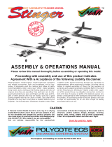
INTRODUCTION
Thank you for purchasing the Great Planes Waco YMF-5
ARF! We offer two options for the builder of this classic model.
Build it as a single seat mail carrier, or as a three seat civilian
open cockpit bipe. You’ll enjoy the great scale-like handling
characteristics of this big bipe and the level of detail we’ve
put into this model. This manual details the installation of
both a glow and gas engine, so please look in the Decisions
You Must Make section for the items required to complete
each type of installation before you begin building.
For the latest technical updates or manual corrections to the
Waco YMF-5 ARF visit the Great Planes web site at www.
greatplanes.com. Open the “Airplanes” link, and then select
the Waco YMF-5 ARF. If there is new technical information or
changes to this model a “tech notice” box will appear in the
upper left corner of the page.
AMA
Academy of Model Aeronautics:If you are not already a
member of the AMA, please join! The AMA is the governing
body of model aviation and membership provides liability
insurance coverage, protects modelers’ rights and interests
and is required to fly at most R/C sites.
Academy of Model
Aeronautics
5151 East Memorial Drive
Muncie, IN 47302-9252
Tele. (800) 435-9262
Fax (765) 741-0057
www.modelaircraft.org
IMPORTANT!!!
Two of the most important things you can do to preserve the
radio controlled aircraft hobby are to avoid flying near full-
scale aircraft and avoid flying near or over groups of people.
PROTECT YOUR MODEL, YOURSELF
& OTHERS… FOLLOW THESE
IMPORTANT SAFETY PRECAUTIONS
1. Your Waco YMF-5 should not be considered a toy, but
rather a sophisticated, working model that functions very
much like a full-size airplane. Because of its performance
capabilities, the Waco YMF-5, if not assembled and operated
correctly, could possibly cause injury to yourself or spectators
and damage to property.
2. You must assemble the model according to the instructions.
Do not alter or modify the model, as doing so may result in an
unsafe or unflyable model. In a few cases the instructions may
differ slightly from the photos. In those instances the written
instructions should be considered as correct.
3. You must take time to build straight, true and strong.

3
4. You must use an R/C radio system that is in good condition,
a correctly sized engine, and other components as specified
in this instruction manual. All components must be correctly
installed so that the model operates correctly on the ground
and in the air. You must check the operation of the model and
all components before every flight.
5. If you are not an experienced pilot or have not flown
this type of model before, we recommend that you get the
assistance of an experienced pilot in your R/C club for
your first flights. If you’re not a member of a club, your local
hobby shop has information about clubs in your area whose
membership includes experienced pilots.
6. While this kit has been flight tested to exceed normal use,
if an engine larger than one in the recommended range is
used, the modeler is responsible for taking steps to reinforce
the high stress points and/or substituting hardware more
suitable for the increased stress.
7. WARNING: The cowl, wheel pants, and some fairings are
made of fiberglass, the fibers of which may cause eye, skin
and respiratory tract irritation. Never blow into or on a part
to remove fiberglass dust, as the dust will blow back into
your eyes. Always wear safety goggles, a particle mask and
rubber gloves when grinding, drilling and sanding fiberglass
parts. Vacuum the parts and the work area thoroughly after
working with fiberglass parts.
We, as the kit manufacturer, provide you with a top quality,
thoroughly tested kit and instructions, but ultimately the
quality and fl yability of your fi nished model depends
on how you build it; therefore, we cannot in any way
guarantee the performance of your completed model,
and no representations are expressed or implied as to the
performance or safety of your completed model.
Remember: Take your time and follow the instructions to
end up with a well-built model that is straight and true.
DECISIONS YOU MUST MAKE
This is a partial list of items required to finish the Waco YMF-5
that may require planning or decision making before starting
to build. Order numbers are provided in parentheses.
Glow Engine Option & Required Parts
If you choose to equip your model with a glow engine, you
will need to purchase the items listed below. Either a two-
stroke or a four-stroke engine can be used. This manual will
show the installation of an O.S. 1.20 four-stroke engine.
❏ 3' [900mm] standard silicone fuel tubing (GPMQ4131)
❏ Suitable propeller per engine manufacturer’s
recommendation
❏ O.S.® Needle Valve Extension kit (optional) (OSMG7290)
Two-Stroke Option
❏ O.S. .95 AX Ringed 2-Stroke engine (OSMG0580)
❏ Bisson Pitts muffler (BISG4091)
Four-Stroke Option
❏ O.S. FS-120S-E Surpass™ Ringed 4-Stroke engine
(OSMG0930)
Gas Engine Option & Required Parts
To equip your Waco with a gasoline engine, we recommend
the DLE-30 gas engine for its power, reliability, and economy.
Regardless of the gas engine you choose, you will also
need to purchase a few other items to set up your model for
gasoline fuel.
❏ DL Engines™ DLE-30cc Gas Engine (DLEG0031)
❏ Sullivan Gasoline Tank Conversion Kit (SULQ2684)
❏ Dubro 1/8" Fuel Line Barbs (DUBQ0670)
❏ Dubro 1/8" ID Tygon Fuel Tubing (DUBQ0493)
❏ Fuel Line Clamps 1/8" (GPMQ4172)
❏ Ernst Charge Jack Receptacle (ERNM3001)
❏ Futaba® NR4RB 4.8V 1000mAh NiCd Receiver Battery
(FUTM1380)
❏ Futaba J-Series Switch w/ Charge Plug (FUTM4370)
❏ (4) 10-32 or M5 bolts, blind nuts, washers, & lock washers
for engine mounts
❏ (4) M4 x 20mm machine screws for cowl installation tool
Radio System Recommendations
❏ 4 Channel Radio System (computer radio with mixing
preferred)
❏ Futaba R617FS 7-Channel 2.4GHz Receiver
(FUTL7627)
❏ (1) Futaba S3004 Standard Ball Bearing Servo
(FUTM0004)
❏ 6) Futaba S9001 Coreless Ball Bearing Servo
(FUTM0075)
❏ Futaba NR4RB 4.8V 1000mAh NiCd Receiver Battery
(FUTM1380)
❏ (2) 16" [405mm] servo extension (FUTM3955)
❏ (1) 12" [300mm] servo extension (HCAM2711)
❏ (1) 30" [760mm] servo extension (EMOM0129)
❏ (1) 21" [533mm] Y-harness (HCAM2500)
❏ (1x or 2x if no computer radio) 6" [152mm] Y-harness
(FUTM4130)
❏ Futaba J-Series Switch w/ Charge Plug (FUTM4370)
❏ Switch & Charge Jack Mounting Set (GPMM1000)
ADDITIONAL ITEMS REQUIRED
Required Hardware and Accessories
To finish this airplane you will need the following items.
❏ (2) 3/8" x 3" Heat Shrink Tubing (DUBM2180)
❏ R/C foam rubber 1/4" [6mm] thick (HCAQ1000)
❏ Drill bits: 1/16" [1.6mm], 5/64" [2mm], 3/32" [2.4mm],
1/8" [3.2mm], 1/4" [6.4mm], 13/32 [10mm], 3/16"
[4.8mm] long drill bit

4
❏ 1 oz. [30g] Medium Pro™ CA+ (GPMR6008)
❏ 1 oz. [30g] Thin Pro CA (GPMR6002)
❏ CA applicator tips (HCAR3780)
❏ CA debonder (GPMR6039)
❏ Pro 30-minute epoxy (GPMR6047)
❏ Pro 6-minute epoxy (GPMR6045)
❏ Epoxy brushes (6, GPMR8060)
❏ Mixing sticks (50, GPMR8055)
❏ Mixing cups (GPMR8056)
❏ Threadlocker™ thread-locking compound (GPMR6060)
❏ R/C-56 canopy glue 4oz (JOZR5007)
❏ Medium T-pins (100, HCAR5150)
❏ #64 rubber bands (1/4 lb [113g] box, HCAQ2020)
❏ Milled fiberglass (GPMR6165)
❏ 18" flexible steel rule (HCAR0460)
❏ Builder’s Triangle Set (HCAR0480)
❏ 2-56 tap and drill set (GPMR8100)
❏
6-32 tap and drill set (GPMR8102)
❏ Tap handle (GPMR8120)
❏ Pliers with wire cutter (HCAR0625)
❏ Hobbico® Heavy Duty Diagonal Cutter 7" (HCAR0627)
❏ Electric drill
❏ Household scissors
❏ Hobbico ball-end hex wrench set – metric (HCAR0521)
❏ Hobbico ball-end hex wrench set – SAE (HCAR0520)
❏ (2) 1" [25mm] C-Clamps
❏ Excel Small Clamp (EXLR5663)
❏ Easy-Touch™ Bar Sander 5.5" (GPMR6169)
❏ Sandpaper assortment
❏ Masking tape
❏ Denatured alcohol (for epoxy clean up)
❏ Paper towels
❏ Plan protector (GPMR6167) or wax paper
Optional Supplies and Tools
❏ 21st Century® sealing iron (COVR2700)
❏ 21st Century iron cover (COVR2702)
❏ Rotary tool such as Dremel®
❏ Rotary tool reinforced cut-off wheel (GPMR8200)
❏ Dremel Drum Sander, Coarse 3/8" (DRER0968)
❏ Hobbico Retractable Fabric Tape Measure (HCAR0478)
❏ Hobbico Z-bend pliers (HCAR2000)
❏ Hobby Heat™ micro torch (HCAR0755)
❏ Panel Line Pen (TOPQ2510)
❏ Dead Center™ Engine Mount Hole Locator (GPMR8130)
❏ AccuThrow™ Deflection Gauge (GPMR2405)
❏ Precision Magnetic Prop Balancer (TOPQ5700)
❏ Great Planes 1/5th scale WWI German Pilot (brown)
(GPMQ9115)
❏ Hobbico Pin Vise 1/16" Collet w/3 Bits (HCAR0696)
❏ Great Planes E-Z Mask Tape 1/8" (GPMR1000)
IMPORTANT BUILDING NOTES
• When you see the term test fit in the instructions, it means
that you should first position the part on the assembly
without using any glue, and then slightly modify or custom
fit the part as necessary for the best fit.
• Whenever the term glue is written you should rely upon
your experience to decide what type of glue to use. When
a specific type of adhesive works best for that step, the
instructions will make a recommendation.
• Whenever just epoxy is specified you may use either
30-minute (or 45-minute) epoxy or 6-minute epoxy. When
30-minute epoxy is specified it is highly recommended that
you use only 30-minute (or 45-minute) epoxy, because you
will need the working time and/or the additional strength.
• Photos and sketches are placed before the step they
refer to. Frequently you can study photos in following steps
to get another view of the same parts.
• The Waco YMF-5 is factory-covered with Top Flite®
MonoKote® film. Should repairs ever be required, MonoKote
can be patched with additional MonoKote purchased
separately. MonoKote is packaged in six-foot rolls, but
some hobby shops also sell it by the foot. If only a small
piece of MonoKote is needed for a minor patch, perhaps a
fellow modeler would give you some. MonoKote is applied
with a model airplane covering iron, but in an emergency a
regular iron could be used. A roll of MonoKote includes full
instructions for application. Following are the colors used on
this model and order numbers for six foot rolls.
Cub Yellow (TOPQ0220)
Black (TOPQ0208)
True Red (TOPQ0227)
• The stabilizer and wing incidences and engine thrust
angles have been factory-built into this model. However,
some technically-minded modelers may wish to check these
measurements anyway. To view this information visit the web
site at www.greatplanes.com and click on “Technical Data.”
Due to manufacturing tolerances which will have little or no
effect on the way your model will fly, please expect slight
deviations between your model and the published values.
KIT INSPECTION
Before starting to build, take an inventory of this kit to make
sure it is complete, and inspect the parts to make sure they
are of acceptable quality. If any parts are missing or are not of
acceptable quality, or if you need assistance with assembly,
contact Product Support. When reporting defective or
missing parts, use the part names exactly as they are written
in the Kit Contents list.
Great Planes Product Support:
3002 N Apollo Drive, Suite 1
Champaign, IL 61822
Telephone: (217) 398-8970, ext. 5
Fax: (217) 398-7721
E-mail: airsuppor[email protected]

8
4
3
5
9
10
14
18
6
11
1
2
27
7
12
15
20 19
21
16
13
22
17
23
24
25
26
5
ORDERING REPLACEMENT PARTS
Replacement parts for the Waco YMF-5 ARF are available
using the order numbers in the Replacement Parts List
that follows. The fastest, most economical service can be
provided by your hobby dealer or mail-order company.
To locate a hobby dealer, visit the Great Planes web site
at www.greatplanes.com. Choose “Where to Buy” at the
bottom of the menu on the left side of the page. Follow the
instructions provided on the page to locate a U.S., Canadian
or International dealer.
Parts may also be ordered directly from Hobby Services
by calling (217) 398-0007, or fax at (217) 398-7721, but full
retail prices and shipping and handling charges will apply.
Illinois and Nevada residents will also be charged sales tax.
If ordering via fax, include a Visa® or MasterCard® number
and expiration date for payment.
Mail parts orders and payments by personal check to:
Hobby Services
3002 N. Apollo Drive, Suite 1
Champaign, IL 61822
Be certain to specify the order number exactly as listed in
the Replacement Parts List. Payment by credit card or
personal check only; no C.O.D.
If additional assistance is required for any reason, contact
Product Support by telephone at (217) 398-8970, or by
e-mail at [email protected].
Order No. Description
NOTE
REPLACEMENT PARTS LIST
Full-size plans are not available.
You can download a copy of this
manual at www.greatplanes.com.
GPMA4065
GPMA4066
GPMA4067
GPMA4068
GPMA4069
GPMA4070
GPMA4071
GPMA4072
GPMA4073
GPMA4074
GPMA4075
GPMA4076
GPMA4077
GPMA4078
GPMA4079
Fuselage Set
Top Wing Set
Bottom Wing Set
Cabane Set
Interplane Struts Set
Landing Gear Set
Wheel Pants
Rudder Set
Horizontal Stab Set
Tailwheel Set
Windscreens Set
Cowl Set
Decal Sheet
Bottom Wing Cover
Cowl Ring Set
KIT CONTENTS
1. Cowl
2. Fuselage
3. Cowl Rings
4. Dummy Engine
5. Landing Gear Fairings
6. Main Landing Gear
7. Turtledeck Fairing
8. Interplane Struts
9. Engine Spacers
10. Wheel Pants
11. Wheels
12. Windscreens
13. Horizontal Tail
14. Landing Gear Center Fairing
15. Wing Fillet Fairings
16. Front Cockpit Cover
17. Horizontal Stab Tubes
18. Belly Fairing
19. Lower Wing Joiners
20. Wing Dowels
21. Cabane Struts
22. Rudder
23. Lower Wing
24. Upper Wing Joiners
25. Servo Mounting Blocks
26.Upper Wing
27. Tailwheel Assembly

6
PREPARE FOR ASSEMBLY
Before you begin assembling your model, use a covering iron
set to a medium temperature (about 250° F [121° C]) to tack
down any loose or wrinkled covering. Securely tack down the
edges of trim and where seams are present and around the
aileron servo hatch covers. We recommend using a Coverite™
(COVR2700) covering iron with a sock (COVR2702).
WING ASSEMBLY
Aileron Servo Preparation
❏ 1. Locate the long servo arm that came with your servo.
For Futaba standard servos this is the arm that is already
installed on the servo. For other radio systems, please use
the arm that is at least 5/8" [15.9mm] long from the center
of the shaft to the outermost hole. Center four servos using
your radio. Remove the servo arm screw and reposition the
servo arm on the splined output shaft so that the arm is 90°
(perpendicular) to the servo case side. Clip off the unused
servo arms so that your servos look like those in the photo.
Install the servo arm screw.
❏ 2. Use a 5/64" [2mm] drill bit to drill the outermost servo
arm hole on all four aileron servos.
Bottom Wing Assembly
❏ ❏ 1. Working with the bottom left wing now, cut out three
1/2" x 1" [13mm x 25mm] pieces of thin card stock (not
supplied). You may use construction paper or a manila folder
for this purpose. Lay the servo on a flat surface with the
arm hanging down over the edge of your table. Locate two
19x19x9mm hardwood blocks. Position the blocks under the
servo mounting tabs and place a piece of card stock in the
locations shown. Holding the blocks and servo in position,
use a 1/16" [1.6mm] drill to drill four holes for the servo
mounting screws.
❏ ❏ 2. Install the four servo mounting screws that came
with your servo. Remove the screws and harden each of the

7
screw holes with thin CA. Let the CA cure and reinstall the
screws. Remember that you are going to set up a left side
servo and a right side servo.
❏ ❏ 3. With the hardwood blocks attached and each servo
arm still centered, position your servo on the aileron servo
bay cover so that the servo arm is centered in the opening.
Glue these in place and hold the blocks to the servo bay
cover with two small clamps. The clamps shown here are
Excel 3-1/2" [89mm] plastic clamps (EXLR5663). Let the
glue cure.
❏ ❏ 4. Mark the approximate center line of each block on
both the wide side and the narrow side of each mounting
block. Using a 1/16" [1.6mm] drill bit, drill one hole into each
block by drilling through the servo bay cover and into the
block. Sighting from the back and from the side, line up the
drill with the marks you made on the blocks.
❏ ❏ 5. Install one #2 x 3/8" [9.5mm] countersunk sheet
metal screw into each block. Remove the screws and harden
the holes you just tapped with a drop of thin CA.
❏ ❏ 6. Attach a 16" [405mm] servo lead extension to the
aileron servo lead. Use a piece of 3/8" [9.5mm] diameter
heat shrink tubing (not supplied) to secure the connection or
simply tape the connectors to secure them. Route the servo
lead through each wing using the supplied guide string.
❏ ❏ 7. Route the other end of the servo lead through the
hole in the top side of the wing.
❏ ❏ 8. Note the orientation of the servo bay cover in
the photo above. Position the completed servo bay cover
properly and install it to the wing using four #2 x 3/8" [9.5mm]
sheet metal screws and four #2 flat washers. Remove the
screws and servo bay covers and harden the screw holes
with a drop of thin CA.

8
❏ ❏ 9. Using a 90° builder’s square or triangle, draw a
1/2" [12.7mm] long line on the aileron straight back from the
servo arm. Take note of the hardwood block that is below the
surface of the covering. You will drill into this block next.
❏ ❏ 10. Center a large nylon control horn over the line
you drew so that the pushrod holes in the horn are directly
over the hinge line of the aileron. With a 1/16" [1.6mm] drill
bit, hold the horn in place and drill two 1/2" [12.7mm] deep
holes using the holes in the horn as a guide. Be careful not
to drill all the way through the aileron. Wrap a piece of
masking tape around your drill bit 1/2" [12.7mm] from the tip
to help you know how deep to drill.
❏ ❏ 11. Install the control horn using two #2 x 1/2" [12.7mm]
sheet metal screws. Remove the screws and the horn and
harden the screw threads you created with a few drops of
thin CA. Reinstall the control horn.
❏ ❏ 12. Fit a nylon clevis to a 12" [305mm] one-end
threaded pushrod so that the end of the threaded rod extends
1/8" [3.2mm] into the clevis barrel. Fit a silicone retainer onto
the pushrod as shown.
❏ ❏ 13. Fit the clevis to the outer hole of the control horn.
With the aileron servo and the aileron centered, mark the
bend line at the outer hole in the servo arm.
❏ ❏ 14. Bend the pushrod wire 90°. Clip off the excess
wire so that the bent section is at least 1/4" [6.4mm] long.
Connect the wire in the outer hole of the servo arm and fit a
nylon Faslink™ to hold it in place. Make any fine adjustments
by removing the clevis from the control horn and turning it in
or out to shorten or lengthen the pushrod. Slide the silicone
retainer in place over the arms of the clevis.
❏ 15. Repeat steps 1 through 14 for the bottom right wing.
❏ 16. For the next few steps, cut up some paper towels into
1/4 sheets and have some denatured alcohol on hand to
clean up any epoxy.
❏ 17. Epoxy the two 37mm x 8mm wing dowels in place
so that at least 3/8" [9.5mm] of each dowel extends forward
from the leading edge.

9
❏ 18. Identify the two 208mm x 15mm bottom wing L.E.
joiners. One is made out of aluminum and one is wood. Identify
the two 105mm x 12mm bottom wing T.E. joiners. Using 180-
grit sandpaper, scuff the side of the aluminum joiner that will
be glued to the wood joiner. Clean the aluminum joiner with
an alcohol-dampened cloth. Mix up a batch of 30-minute
epoxy and coat the faces of each joiner. Glue the two L.E.
joiners together and the two T.E. joiners together so that you
now have one long and one short joiner. Take note of the
dihedral “V” angle in the joiners. Align the pieces and clamp
them together. Let the epoxy cure. Then, remove the clamps.
❏ 18. Orient the wings so that they are both facing up. Apply
some 30-minute epoxy into the L.E. and T.E. joiner slots. Apply
epoxy to both sides of each joiner. Fit the long L.E. joiner into
the L.E. slot so the “V” in the joiner is upright. Fit the short T.E.
joiner into the T.E. slot the same way. Thoroughly coat the root
rib of both wings with epoxy and fit the wings together.
❏ 20. Fit the two 1/4-20 x 2" nylon wing bolts and use some
#64 rubber bands to hold the wings together while the epoxy
cures. Use three rubber bands on the dowels to hold the L.E.
together. Put two rubber bands on the top side of the wing
and two on the bottom side with the bolts half way through
the holes.
❏ 21. Use paper towels and some denatured alcohol to
clean up any excess epoxy that is squeezed out of the joint.
Allow the epoxy to fully cure.
Top Wing Assembly
❏ 1. Prepare a left and a right servo and fit each one to its
respective servo bay cover as you did for the lower wing.
❏ 2. Connect a 12" [300mm] servo lead extension to the left
wing servo. Because of the hole in the center wing panel, the left
wing servo will use a shorter servo lead extension. Use some
3/8" [9.5mm] heat shrink tubing or tape to secure the connector.
❏ 3. Route the servo lead through the left wing and install
the servo bay cover using four #2 x 3/8" [9.5mm] sheet metal
screws and four #2 flat washers. Harden the screw holes
with thin CA.

10
❏ 4. Connect a 30" [760mm] servo lead extension to the
right wing servo. Secure the connection with heat shrink
tubing or tape. Route the servo lead through the wing and
install the servo bay cover using four #2 x 3/8" [9.5mm] sheet
metal screws and four #2 flat washers.
❏ 5. Line up and install the aileron control horns using the
same method recommended earlier for the bottom wing. Drill
two 1/2" [12.7mm] deep holes using a 1/16" [1.6mm] drill.
Install the horns with two #2 x 1/2" [12.7mm] sheet metal
screws per horn.
❏ 6. Prepare two 12" [305mm] one-end threaded pushrods
using two clevises and two silicone retainers.
❏ 7. Fit the clevis to the outer hole in the control horn. Mark
and bend the rod as you did earlier. Clip off the excess
pushrod wire leaving 1/4" [6.4mm] of wire and fit the pushrod
to the outer hole of the servo arm. Secure the pushrod at the
servo arm with a nylon Faslink. Adjust the pushrod length at
the clevis. Secure the clevis with the silicone retainer.
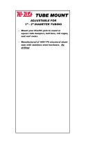
Top wing center
section to cabane
(x4)
Cabane strut to
fuselage bracket
(x4)
Interplane
strut bracket
(x8)
140° 115° 105°
❏ 8. Identify the bag of four steel brackets for the top wing
center section. These are the brackets that have the 140°
bend angle (or the brackets with the flattest bend).
❏ 9. Use four #4 x 1/2" [12.7mm] sheet metal screws
to attach the brackets to the wing center section in the
orientation shown so that they are angled inward toward the
fuselage center line. Remove the screws and brackets and
harden the screw holes with thin CA. Reinstall the brackets.
❏ 10. Attach the guide string in the wing center section to
the long servo extension of the right wing aileron servo. Pull
the servo lead through the center section and route the lead
through the hole in the front left corner of the bottom of the
center section. Leave the guide string attached until after
you have glued together the wings.

11
❏ 11. Two joiners are needed to join the top left wing to the
center wing section and two joiners are needed to join the
right wing to the center section. Scuff and clean the aluminum
joiner the same as was done for the bottom wing. Mix up a
batch of 30-minute epoxy and glue each 235mm x 15mm
aluminum L.E. joiner to a matching ply joiner. Be careful when
matching the dihedral angle of the joiners when you’re gluing
them together because the angle is very shallow. Clamp
these together and allow the epoxy to cure.
❏ 12. Glue a pair of 125mm x 13mm plywood T.E. wing
joiners together. Then, glue the remaining pair of 125mm x
13mm ply joiners to each other. Clamp these together and
allow the epoxy to cure.
❏ 13. Apply some epoxy into the L.E. and T.E. joiner slots of
both the right wing and the right side of the center section.
Coat the joiners with epoxy. Then, fit the long L.E. joiner
into the leading edge slot and the short T.E. joiner into the
trailing edge slot. Coat the root ribs of the right wing and
the right side of the center section and join the right wing to
the center section. Make sure you orient the joiners correctly
with the dihedral angle upright. Note: To protect the servo
lead contacts, wrap the connector in masking tape.
❏ 14. Do the same for the left wing, coating the joiners and
ribs with epoxy. When you’re ready to slide the left wing onto
the center section, route the servo lead through the root rib
of the center section and out of the exit hole.
❏ 15. Slide the wings together tightly. Hold them together
using masking tape. Stretch one long piece across the span
so the ends wrap around the wing tips. Do this for the top
and the bottom side of the wing to ensure that the tape does
not slip.
❏ 16. Clean up any excess epoxy with denatured alcohol
and paper towels. Set the wing aside and let the epoxy cure.
Carefully remove the masking tape.

12
ASSEMBLE THE FUSELAGE
Main Landing Gear Installation
❏ 1. Install the main landing gear onto the fuselage using five
6-32 x 3/4" [19.1mm] SHCS, five #6 split lock washers, and
five #6 flat washers. Use a drop of thread locking compound
on the screw threads.
❏ 2. Install the main landing gear center fairing. Apply glue
to the base of the fairing or the bottom of the aluminum gear
strap. Note: The center fairing is not symmetrical, so please
note the contours of the fairing and install it so that it matches
the fuselage. (If you need to remove the landing gear in the
future, trim away the covering over the access hole.)
❏ 3. Test fit the gear to fuse fairings. Note: There is a left
and right fairing. The smaller radius side of each fairing faces
inside. With the fairings up against the fuselage, wrap some
1/8" EZ-Mask tape (GPMR1000) or a narrow strip of regular
masking tape about 1/16" [1.6mm] above the bottom edge
of each fairing.
❏ 4. Remove one gear fairing at a time and apply a 3/16"
[4.8mm] bead of R/C-56 canopy glue around the base of
the gear leg using the masking tape as a guide. Fit the gear
fairing back onto the gear leg. Repeat this for the other leg.
❏ 5. Tape the fairings up against the fuselage to hold them
in place. Remove the tape after the glue dries. Gluing all
the fairings to the landing gear will allow you to remove the
landing gear easily if you have to in the future.
❏ 6. Cut 1/4" [6.4mm] off of the end of both main landing
gear axles. A Dremel® rotary tool with a cutoff wheel
attachment is handy for doing this. Otherwise, use a table
vise and a hacksaw.

13
❏ 7. File a 1/4" [6.4mm] wide flat spot at a distance 3/16"
[4.8mm] from the base of the axle. File another one that is
1-9/16" [40mm] from the base of the axle.
❏ 8. Install a 3-1/2" [89mm] wheel onto each axle using two
3/16" [4.8mm] wheel collars with two 6-32 x 1/4" [6.4mm]
SHCS. Apply a drop of blue thread locking compound to the
locking screw threads to prevent the screws from backing out.
❏ 9. Using a 5/16-24 lock nut, install each axle assembly
onto the main landing gear. Make sure that the heads of the
set screws face directly down with respect to the model.
Cabane Strut Installation
❏ 1. Identify the eleven wood pieces that make up the
carrying handle. Study the photo layout carefully. The center
“handle” parts have no bolt holes and there are three of
them. Glue these three together. Glue the other “doubled”
parts together, being careful to line up the bolt holes and
orient the slots properly. Note: You may use your choice of
glue, but wood glue will give you the longest working time
allowing you to fit everything together correctly.
❏ 2. Fit the parts together as shown. Join the center handle
and the two cabane braces to one of the spanwise braces.
Then, join the other spanwise brace to the assembly. Clamp
the pieces together or wrap masking tape around the braces
to hold them as the glue dries. Press four #4 blind nuts into
the holes of the cabane braces from the inside as shown.
Apply some 5-minute epoxy around the outside edges of the
blind nuts to hold them permanently in place. Be careful not
to get any epoxy into the screw threads.

14
❏ 3. Identify the cabane bracket set for the fuselage. These
four brackets are bent at 115° (the second flattest bend). Bolt
these brackets to the fuselage using four 4-40 x 3/4" [19.1mm]
SHCS, four #4 lock washers, and four #4 flat washers. Use
a drop of thread locking compound on the screw threads.
Note the orientation of the cabane struts. Use four 4-40 x 1/2"
[12.7mm] SHCS, four #4 flat washers, and four #4 lock nuts to
bolt the struts to the brackets. Bolt these on so that the heads
of the screws face up with the washer under the screw head.
❏ 4. Using four 4-40 x 3/4" [19.1mm] SHCS and four #4
flat washers, bolt the finished carrying handle to the cabane
struts. Leave the handle in place whenever the wings are off
of the fuselage. This will prevent accidental damage to the
cabanes and brackets.
Horizontal Stabilizer, Tailwheel
and Rudder Installation
❏ 1. Once again, you’ll need to have your epoxy supplies
nearby and ready. Set the model down on its wheels. Fit the
short 165mm x 10mm aluminum tube into the L.E. hole in the
fuselage and the long 270mm x 10mm tube into the T.E. hole.
❏ 2. Mix up a batch of 30-minute epoxy. Coat the stabilizer
tubes and the root rib of each stabilizer with epoxy. Note:
There is no left or right stabilizer. Any stabilizer can be placed
on any side.
❏ 3. Fit the stabilizers to the fuselage. Hold the stabs tight
up against the fuse with masking tape. Clean up any excess
epoxy with denatured alcohol and paper towels.

15
❏ 4. Remove the two 3mm wheel collars and the tailwheel
from the tailwheel assembly. Grind two 1/8" [3.2mm] flat
spots on the axle so that one is centered 1/8" [3.2mm] from
the support arm and one is centered 7/8" [22.2mm] from the
support arm.
❏ 5. Reinstall the wheel and the wheel collars. Apply one
drop of thread locking compound to the locking screw
threads and tighten the locking screws against the flat spots
you created on the axle.
❏ 6. Prepare the three CA hinges for the rudder by inserting
a T-pin through the center of the hinge.
❏ 7. Test fit the hinges and the tail wheel into the pre-cut
slots in the fuselage. Test fit the rudder onto the hinges and
onto the tailwheel guide wire. The rudder hinge line should
have only a small gap with the T-pins holding the hinges
centered. Use the back side of your hobby knife to dig out the
hinge slots if you can’t fully insert a hinge.Slide the rudder
up or down so there is just enough of a gap between the
fin and the rudder counterbalance to allow full rudder travel.
Remove the rudder from the fin.

16
❏ 8. Remove the tailwheel assembly and add a few drops
of lightweight machine oil to each hinge bushing. Clean the
surface of the hinge straps with some alcohol.
❏ 9. Apply 30-minute epoxy to the hinge straps and fit the
tailwheel to the fuselage. Wipe up any excess epoxy to keep
it from interfering with the operation of the tailwheel steering.
Apply some epoxy to the tip of the tailwheel guide wire and
into the corresponding hole in the rudder.
❏ 10. Fit the rudder. Remove the T-pins and deflect the
rudder right and left several times as you push the rudder up
against the hinge line. Hold the rudder up against the hinge
line as you deflect it one direction. Wick about 5-8 drops
of thin CA into each hinge. Deflect the rudder the opposite
direction and wick CA into the other side of each hinge.
Pushrod, Control Horn and
Servo Installation
❏ 1. Turn the model over. Slide two 36" [914mm] pushrods
into the left and right elevator pushrod guide tubes so that
the unthreaded end goes to the servo tray inside of the fuse.
❏ 2. Using the pushrods as a guide, mark the elevators
where you will install the control horns. Use a builder’s
square or triangle to help you project the line directly down
from the pushrod or use the control horn to help you do this.
❏ 3. Remove the pushrods or slide them forward out of your
way. Center a control horn over the line you drew on each
elevator so that the pushrod holes in the horn are directly
over the hinge line. Hold the horn in position and drill two 1/2"
[12.7mm] deep holes using a 1/16" [1.6mm] drill. Be careful
not to drill completely through the elevators.
❏ 4. Install the control horns
using two #2 x 1/2" [12.7mm]
sheet metal screws per horn.
Harden the screw holes with
thin CA.

17
❏ 5. Install a nylon clevis and a silicone retainer on each
elevator pushrod. Be sure to screw the pushrod into the clevis
far enough so that at least 1/8" [3.2mm] of the threaded end
extends into the clevis barrel. If you removed the pushrods,
slide them back into the pushrod guide tubes. Fit the clevises
to the outer hole of the elevator horns. Slide the silicone
retainer into position.
❏ 6. Use the last 36" [914mm] pushrod to mark the position
of the rudder control horn. Position a control horn over the
mark you made and drill two 1/2" [12.7mm] deep holes using
a 1/16" [1.6mm] drill bit. Install the control horn using two #2
x 1/2" [12.7mm] sheet metal screws.
❏ 7. Install a nylon clevis and a silicone retainer on the
rudder pushrod. Fit the clevis to the outer hole of the rudder
horn and slide the silicone retainer into position.
❏ 8. Use a piece of masking tape to tape each elevator
counterbalance to the stabilizer so that the elevators will
remain centered for the next few steps.
❏ 9. Prepare one servo so that the servo arm is 90° to the
servo case. Clip off the unused arms so that your servo looks
like the one shown above. Align your servo so that the second
outermost hole (or the hole that is 1/2" [12.7mm] from the
center of the servo output shaft) is centered between the two
elevator pushrods. Install the servo in that position using a
1/16" [1.6mm] drill and the screws that came with your servo.
❏ 10. Make an equal bend in each pushrod wire 1-1/2"
[38mm] back from the holes in the servo arm so that each
wire points straight forward. Cut the left elevator pushrod 3/4"
[19.1mm] forward of the bend. Cut the right elevator pushrod
1/2" [12.7mm] forward of the servo arm holes.

18
❏ 11. Fit two 3/16" [4.8mm] wheel collars onto the elevator
pushrod wires. Use a drop of thread locking compound on
the screw threads and fit two 6-32 x 1/4" SHCS. With both
elevators centered, tighten the collar locking screws to hold
the two wires together securely.
❏ 12. Mark the pushrod at the servo arm and make a 90°
vertical bend. Drill the second outermost servo arm hole
using a 5/64" [2mm] drill. Fit the pushrod to the servo arm.
Secure the pushrod with a nylon Faslink. Cut off the excess
pushrod wire. Install the servo arm screw.
❏ 13. If you need to make any minor adjustments to the
elevators, make the adjustments at the individual elevator
clevises rather than at the collars. Remember to secure
the clevises with the silicone retainers when you are done
making adjustments.
❏ 14. Use a 1/16" [1.6mm] drill bit to install the rudder servo
so that the outermost hole in the servo arm is aligned with the
rudder pushrod wire as shown. Note: The servo arm must
be positioned on the output shaft so that there is a 90° bend
between the arm centerline and the pushrod. Choose the
servo arm that aligns best and clip off the remaining servo
arms. Remember to harden the screw holes with thin CA.
❏ 15. Mark the rudder pushrod at the servo arm hole and
make a 90° bend. Drill a 5/64" [2mm] hole. Install the pushrod
on the servo arm and secure it with a nylon Faslink. Cut off
the excess pushrod wire. Install the servo arm screw.
❏ 16. Make any adjustments to the pushrod length to center
the rudder and re-secure the clevis with the silicone retainer.
GLOW ENGINE INSTALLATION
This section will cover the installation of an O.S. FS-1.20S-E
Surpass four-stroke glow engine. A two-stroke .91 sized
engine can be installed with a Pitts-style muffler. If you
are installing a different engine, please respect the firewall
to prop washer dimension of 6-11/16" [170mm]. Plywood
spacers are included that work with the two bolt patterns
etched on the firewall. This engine is best mounted with the
cylinder on the right side and the exhaust facing down.
Mount the Engine
❏ 1. To install the O.S. FS-1.20S-E Surpass four-stroke
glow engine (or any engine using the supplied nylon engine
mount), drill the firewall at the four engraved “+” marks on the
firewall using a 3/16" [4.8mm] drill. These marks line up with
the two nylon engine mount halves that are supplied in this
kit. If you plan on using a different engine mount, please use
the vertical and horizontal centerline “crosshair” marks on
the firewall to line up the template that came with your mount.

19
❏ 2. Install the four 8-32 blind nuts on the firewall from the
back side. Use four 8-32 x 1" [25.4mm] SHCS with four #8
flat washers to help draw the blind nuts into the holes.
❏ 3. Break the tangs out of the two engine mount halves.
File or trim away any portion that remains.
❏ 4. Identify the six
glow engine spacers by
matching the bolt holes
on the spacers to the
bolt holes on the back
of the engine mount.
For this installation,
you will need three of
these spacers.
❏ 5. Fit the two engine mount halves together. Using three
glow engine spacers behind the mount, loosely fit the mount
to the firewall using four 8-32 x 1-1/2" [38mm] SHCS, four #8
lock washers, and four #8 flat washers. Adjust the width of the
mount as you fit the engine. Slide the engine forward or back
on the mount until the drive washer is 6-11/16" [170mm] from
the face of the firewall. Hold the engine in place with two 1"
[25.4mm] adjustable clamps. With the engine in position, use
a Great Planes Dead Center™ Engine Mount Hole Locator
(GPMR8130) to drill four pilot holes or mark the position of
the holes onto the engine mount legs with a felt-tipped silver
marker.
❏ 6. Remove the engine from the mount. Remove the
mounts from the model. Drill and tap the holes for 8-32 bolts
using a tap and drill set (GPMR8103).
❏ 7. Mix up some 30-minute epoxy and thin it down with a
little denatured alcohol. Glue the ply spacers together and
coat them with epoxy to fuelproof them.
❏ 8. Install the engine mount with the ply spacers using four
8-32 x 1-1/2" [38mm] SHCS, four #8 lock washers, and four
#8 flat washers. For added security, use a drop of thread
locking compound on the screw threads. Then, install the
engine to the mount using four 8-32 x 1" [25.4mm] SHCS,
four #8 lock washers, and four #8 flat washers. Center the
engine mount marks with the cross-hairs on the firewall.
Tighten all screws.
Hook Up the Throttle
❏ 1. Using a long drill bit, drill a 3/16" [4.8mm] hole through
the firewall in line with the engine’s throttle arm. If you don’t
have a long drill bit, mark the position of the throttle arm and
remove the engine before you drill the hole.
❏ 2. Dry fit the 24" [610mm] gray outer pushrod tube in
the hole you just drilled. Slide the pushrod tube though the
access holes in the formers and back to the servo tray.

20
❏ 3. Fit a screw-lock pushrod connector to the outermost
hole on short servo arm. Choose the arm that is 90° to the
servo case at 1/2 throttle. Clip off the unused servo arms.
Use a nylon retainer to secure the pushrod connector to the
servo arm. Place a drop of thread locking compound on the
screw threads and fit a 4-40 x 1/8" [3.2mm] SHCS. Fit the
servo arm onto the servo. Install the throttle servo in the
servo tray so that the end of the servo arm is in line with the
pushrod tube.
❏ 4. Position the pushrod tube about 4" [102mm] from the
servo. Cut the pushrod tube 3/8" [9.5mm] forward of the
firewall. Fit the wooden pushrod tube standoff inside the
fuselage at the former that lines up with the leading edge of
the lower wing. Mark the position of the standoff with a felt
tipped pen. Remove the pushrod tube and sand the outside
of the tube at the place that you marked and at the firewall
end of the tube.
❏ 5.
Glue the pushrod tube in place at the firewall using epoxy.
❏ 6. Thread a nylon clevis onto a 36" [914mm] pushrod and
fit a silicone retainer. Insert the pushrod into the pushrod
guide tube. Slide the pushrod into the screw lock pushrod
connector. Connect the clevis to the throttle arm. Secure the
clevis with a silicone retainer. Do not tighten the screw lock
pushrod connector yet.
❏ 7. Turn on your radio and check to see that the servo
moves in the proper direction. With the throttle servo and
the throttle set to full, tighten the screw on the screw lock
pushrod connector. Cut off any excess pushrod and test the
operation of the throttle. Glue the wooden standoff to the
former as shown so that the pushrod tube is supported.
❏ 8. Install the servo arm retaining screw. Use this
opportunity to set up a throttle cutoff and a flight timer on
your transmitter.
/