Topcon RT-5SW User manual
- Category
- Measuring, testing & control
- Type
- User manual

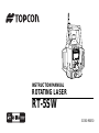
INSTRUCTION MANUAL
ROTATING LASER
RT-5SW
31380 90050

FCC WARNING
Changes or modifications not expressly approved by the manufacturer for compliance could void the user’s
authority to operate the equipment.
In order to comply with FCC radio-frequency radiation exposure guidelines for an uncontrolled exposure, this
device and its antenna must not be co-located or operating in conjunction with any other antenna or transmitter.
The term "IC:" before the radio certification number only signifies that Industry Canada technical specifications
were met.
"Operation of this device is subject to the following two conditions: (1) this device may not cause interference,
and (2) this device must accept any interference, including interference that may cause undesired operation of
the device."
"The installer of this radio equipment must ensure that the antenna is located or pointed such that it does not
emit RF field in excess of Health Canada limits for the general population; consult Safety Code 6, obtainable
from Health Canada's website www.hc-sc.gc.ca/rpb".
Declaration of Conformity
Model Number: RT-5SW/RC-300W
Trade Name: TOPCON CORPORATION
Responsible party: TOPCON POSITIONING SYSTEMS,Inc.
Address: 7400 National Drive,Livermore, CA 94551, U.S.A.
Telephone number: 925-245-8300
This device complies with Part 15 of the FCC Rules. Operation is subject to the following two conditions:
(1) This device may not cause harmful interference, and (2) this device must accept any interference
received, including interference that may cause undesired operation.

1
Foreword
Thank you for purchasing the Topcon RT-5SW Rotating Laser.
It is one the world’s most advanced and accurate grade-setting lasers. To quickly and effectively use
the RT-5SW, please read these brief instructions carefully, and keep them in a convenient location
for future reference.
Handling Precautions
Guarding the instrument against shock
When transporting the instrument, provide some protection to minimize risk of shock. Heavy
shocks may affect beam accuracy.
Caution:
Use of of adjustment controls or performance procedures other than those specified herein may
results in hazardous radiation exposure.

2
Safety Information
In order to encourage the safe use of products and prevent any danger to the operator and others or
damage to properties, important warnings are put on the products and inserted in the instruction
manuals.
We suggest that everyone understand the meaning of the following displays and icons before
reading the “Safety Cautions” and text.
• Injury refers to hurt, burn, electric shock, etc.
• Physical damage refers to extensive damage to buildings or equipment and furniture.
Display Meaning
WARNING
Ignoring or disregard of this display may lead to death or serious injury.
CAUTION
Ignoring or disregard of this display may lead to personal injury or physical damage
to the instrument.
The user of this product is expected to follow all operating instructions and make periodic checks
of the product’s performance. The manufacturer or its representatives assume no responsibility
for results of the use of this product including any direct, indirect, consequential damage, and loss
of profits.

3
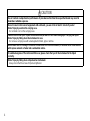
Safety Cautions
WARNING
There is a risk of fire, electric shock or physical harm if you attempt to disassemble or repair the instrument
yourself.
This is only to be carried out by TOPCON or an authorized dealer,only!
Laser beams can be dangerous, and can cause eye injury if used incorrectly .
Never attempt to repair the instrument yourself.
Laser beams can be dangerous. They can cause eye injury.
Do not stare into beam.
High temperature may cause fire.
Do not cover the charger while it is charging.
Risk of fire or electric shock.
Do not use damaged power cable, plug and socket.
Risk of fire or electric shock.
Do not use a wet battery or charger.
May ignite explosively.
Never use an instrument near flammable gas, liquid matter, and do not use in a coal mine.
Battery can cause explosion or injury.
Do not dispose in fire or heat.
Risk of fire or electric shock.
Do not use any power voltage except the one given on manufacturers instructions.
Battery can cause outbreak of fire.
Do not use any other type of charger other than the one specified.
The short circuit of a battery can cause a fire.
Do not short circuit battery when storing it.

4
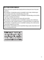
CAUTION
Use of controls or adjustment or performance of procedures other than those specified herein may result in
hazardous radiation exposure.
Do not connect or disconnect equipment with wet hands, you are at risk of electric shocks if you do!
Risk of injury by overturn the carrying case.
Do not stand or sit on the carrying cases.
Please note that the tips of tripod can be hazardous,be aware of this when setting up or carrying the tripod.
Risk of injury by falling down the instrument or case.
Do not use a carrying case with a damaged which belts, grips or latches.
Do not allow skin or clothing to come into contact with acid from the batteries, if this does occur then wash off
with copious amounts of water and seek medical advice.
It could be dangerous if the instrument falls over, please check that you fix the instrument to the tripod
correctly.
Risk of injury by falling down a tripod and an instrument.
Always check that the screws of tripod are tightened.

5
EXCEPTIONS FROM RESPONSIBILITY
1) The user of this product is expected to follow all operating instructions and make periodic checks of the product’s
performance.
2) The manufacturer, or its representatives, assumes no responsibility for results of a faulty or intentional usage or
misuse including any direct, indirect, consequential damage, and loss of profits.
3) The manufacturer, or its representatives, assumes no responsibility for consequential damage, and loss of profits by
any disaster, (an earthquake, storms, floods etc.).
A fire, accident, or an act of a third party and/or a usage any other usual conditions.
4) The manufacturer, or its representatives, assumes no responsibility for any damage, and loss of profits due to a
change of data, loss of data, an interruption of business etc., caused by using the product or an unusable product.
5) The manufacturer, or its representatives, assumes no responsibility for any damage, and loss of profits caused by
usage except for explained in the user manual.
6) The manufacturer, or its representatives,assumes no responsibility for damage caused by wrong movement, or action
due to connecting with other products.

6
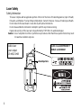
Laser Safety
Safety Information
This laser complies with all applicable portions of title 21 of the Code of Federal Regulations, Dept. of Health,
Education, and Welfare: Food and Drug Administration: Center for Devices : Bureau of Radiological Health.
Do not stare into the laser beam or view directly with optical instruments.
Do not disassemble the instrument or attempt to perform any internal servicing.
Repair and servicing of this laser are to be performed by TOPCON or its authorized dealer.
Caution : Use of adjustment controls or performance procedures other than those specified herein may result
in hazardous radiation exposure.
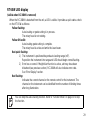
Visible laser
Laser output:
4.5 mW/2.5mW
CLASS IIIa LASER PRODUCT
VISIBLE LASER BEAM
Beam Aperture

7
Contents
Foreword..........................................................................................................................1
Handling Precautions.................................................................................................1
Safety Information......................................................................................................2
Safety Cautions ........................................................................................................3
Laser Safety...............................................................................................................6
Contents ....................................................................................................................7
Standard System Components..................................................................................9
Nomenclature.................................................................................................................10
Sample Display........................................................................................................11
Key Functions..........................................................................................................12
Basic Operation..............................................................................................................13
Preparation and Functions.............................................................................................14
Power Source..........................................................................................................14
Setting Instrument Up..............................................................................................14
RC-300W Remote Controller...................................................................................15
Power Switch...........................................................................................................17
Battery Status Display .............................................................................................19
Setting Grades.........................................................................................................20
How to enter grade ..................................................................................................21
Automatic Alignment................................................................................................22
Executing Automatic alignment ...............................................................................24
Automatic grade setting...........................................................................................25
Executing Automatic grade setting ..........................................................................25
Single axis ...............................................................................................................26

8
Dual axes.................................................................................................................26
How to change the rotary head speed (300, 600, 900 R.P.M.) ...............................28
Height Alert function ................................................................................................28
RT-5SW LED display...............................................................................................29
Masking (Laser beam shutter).................................................................................30
Change the masking mode......................................................................................31
Function Mode ...............................................................................................................33
How to set the options.............................................................................................37
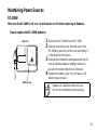
Maintaining Power Sources ...........................................................................................39
RC-300W.................................................................................................................39
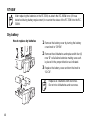
RT-5SW...................................................................................................................40
Dry battery ...............................................................................................................40
Rechargeable battery ..............................................................................................41
Check and Adjusting......................................................................................................43
Horizontal Calibration ..............................................................................................43
Horizontal Rotation Cone Error................................................................................48
Grade Setting Error..................................................................................................49
Storage Precautions.......................................................................................................51
Standard / Optional Accessories....................................................................................52
Specifications.................................................................................................................57
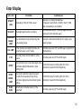
Error Display ..................................................................................................................59

9
Standard System Components
1) Instrument .................................1pc.
2) Level sensor LS-70A..................1pc.
3) Level sensor holder model 6......1pc.
4) Target.........................................1pc.
5) Carrying case.............................1pc.
6) Instruction manual.....................1vol.
7) Battery holder DB-64C...............1pc.
8) Ni-MH battery pack BT-63Q.......1pc.
9) AC/DC converter AD-9B/7C.......1pc.
• Please make sure that all of above items are in the box when you unpack.

10
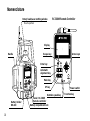
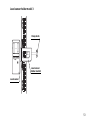
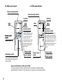
Nomenclature
Rotary head/Laser emitting window
Beam aperture
RC-300W Remote Controller
Handle
Battery holder
DB-64C
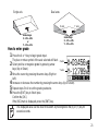
Panel / RC-300W
Remote controller
Battery compartment lock
Display
Escape key
Enter key
Automatic
alignment key
Mask key
XY key
Rotation speed key
Function key
Power switch
Arrow keys

11
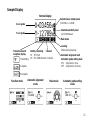
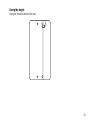
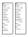
Sample Display
Function mode
Automatic alignment
mode
Mask mode
Normal display
X axis grade
Y axis grade
Selected laser output power
Hi:4.5mW Lo:2.5mW
Selected sensitivity level
1,2, M (M:Manual)
Leveling
(Blinks during leveling)
Transmission and
reception display
Automatic alignment mark
Automatic grade setting mark
ON : Alignment is done.
OFF : Alignment is not done.
Battery remaining
RT : RT-5SW
RC : RC-300W Remote controller
Transmitting
Complete
Incomplete
Mask mode
Automatic grade setting
mode
Channel

12
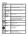
Key Functions
Enter key End Operation of Data Input and Sends data to the instrument.
Escape key Cancels input or Escape to Previous status.
Automatic alignment/
Automatic grade set
key
Executes Automatic alignment / Automatic grade set mode.
Mask key
(Beam shutter)
Sets the laser mask (shutter).
Function key Function mode. The following functions can be set.
Laser output power/ Sensitivity level/ Height Alert/ Alarm signal
/ Masking mode/ Setting the target/ Channel setting
XY key Sets each grade axis.
Speed key Changes the rotary head speed.
300/600/900 r.p.m.
Arrow keys Changes the function page / Selects the items.
Inputs the grades of X Y axis.
Sets the masking direction.
Power switch On/Off of the RT-5SW and RC-300W.
(RC-300W has auto-cut off 60 seconds function)

13
Basic Operation
1 Set the instrument on a tripod or smooth surface
and power ON.
If you want to use RC-300W for remote control, remove it
from the instrument and power on.
To precisely align the instrument, use the Automatic
alignment function. See “Automatic Alignment” and
“Executing Automatic alignment” sections.
2 Set X and/or Y axis grades.
3 Turn on LS-70A level sensor. Check the operation
surface by using the LS-70A level sensor. If high-
precision detection is desired, select that setting
on the LS-70A.
(For more information about LS-70A level sensor refer to
“Standard / Optional Accessories” section.)
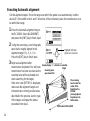
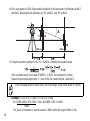
4 Check the rotating beam elevation using the LS-
70A level sensor.
Normal precision mode
High precision
mode
Level sensor
Higher than datum position
(Buzzer sound:High frequent
beep sound)
Move the sensor downward.
Datum position
(Buzzer sound:Continuous
beep sound)
Lower than datum position
(Buzzer sound:Low frequent
beep sound)
Move the sensor upward.

14
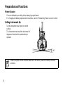
Preparation and Functions
Power Source
Connect the battery according to the battery type purchased.
For charging and battery replacement instructions, see the “Maintaining Power sources” section.
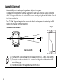
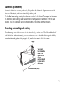
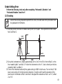
Setting Instrument Up
Set the instrument on a tripod or smooth
surface.
The instrument must be within horizontal ±5
degrees of true level for auto-leveling to
operate.
When using the remote controller attached to the device, lower the remote controller
antenna.
±5°

15
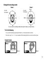
RC-300W Remote Controller
The panel of the instrument can be removed for wireless remote controller RC-300W.
To remove the RC-300W, first push it up then pull it straight away from the instrument.
Operating the RC-300W
The RC-300W will always operate the RT-5SW while attached to
the unit. It will also operate the RT-5SW remotely when detached
from the instrument.
The RC-300W both sends and receives information from the RT-
5SW when it is used within 300m(984ft) of the instrument.
When attached to the RT-5SW, the RC-300W receives its power
from the instrument. In remote operation, the RC-300W must have
batteries installed. See “Maintaining Power Sources” section.
When entering information in the RC-300W, you must always press
the [ENT] key to send the information to the RT-5SW.
The [OK] indicator is displayed on the RC-300W LCD to confirm
communication with the RT-5SW. If communication fails, [NG] is
displayed.
The remote control will automatically turn off about 60 seconds after
the last time any key is pressed or after leveling is completed (auto
cut off function). To reactivate the RC-300W, press the power
switch once.
When using the remote controller, raise the remote controller antenna.

16
1) The working range of the remote controller is up to a distance of about 300 m from
the instrument.
2) It is necessary to install batteries when using the remote controller. Install the
batteries by referring to “Maintaining Power Sources” on page 39. The power supply
of the remote controller is drawn from the instrument when attached.
3) The power of the remote controller shuts off automatically after about 60 seconds
when key or leveling operations have been completed (Auto Shutoff Function). Press
the power switch once to restore power to the remote controller after the auto shutoff
function has been activated.
Common use of RC-300W remote controller
RC-300W remote controller is available for number of RT-5SW. When you are using plural RT-
5SW at your job site, you can use your RC-300W for the other RT-5SW unit. Change the
channel to receive the internal data of each RT-5SW to the RC-300W by operating the RC-
300W.
This function enables to operate RC-300W without re-attach to every RT-5SW which you are
using. The data of each unit can be transmitted to the RC-300W before operating.
See page 35 for the operation “7) Channel Setting”.
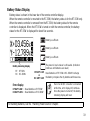
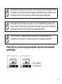
Transmission and reception display
Transmitting Complete Incomplete

17
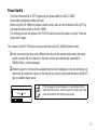
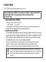
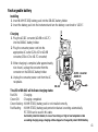
Power Switch
Turn the instrument ON or OFF by pressing the power switch on the RC-300W.
Auto-leveling and grade setting will begin.
When using the RC-300W for wireless remote control, also turn the instrument ON or OFF by
pressing the power switch on the RC-300W.
The following screen will appear if the RT-5SW did not receive the power on signal. Press the
power switch again.
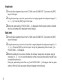
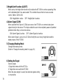
The channel on the RT-5SW does not agree with that on the RC-300W (Remote mode).
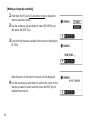
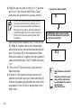
1 If the channel on the main unit is different from that on the remote control when the power
switch is turned ON, the channel on the main unit will be automatically searched for.
[SEARCHING...] will be displayed.
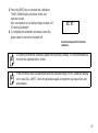
2 When the search is finished, the available channels will be displayed. Use the arrow key (up
and down) to position the cursor on the channel you want to select and then press the [ENT]
key to establish that channel.
If the message shown left appears, it may indicate that the
radio transmission fails. Put the remote controller back to the
main unit and then turn ON the power again.

18
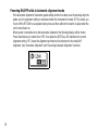
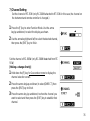
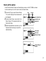
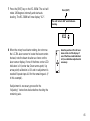
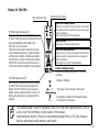
Powering ON/OFF while in Automatic alignment mode
If the Automatic alignment / Automatic grade setting function has been used to precisely align the
grade axis, the alignment setting is maintained when the instrument is turned off. This allows you
to turn off the RT-5SW to save power during non-use times without the need to re-align when the
unit is turned back on.
When power is turned back on after Automatic alignment, the following display will be shown.
Press the allow keys to select No or YES, then press the [ENT] key. NO maintains the current
alignment setting. YES clears the alignment and returns the instrument to the default XY
alignment. (see “Automatic Alignment” and “Executing Automatic Alignment” sections.)
Page is loading ...
Page is loading ...
Page is loading ...
Page is loading ...
Page is loading ...
Page is loading ...
Page is loading ...
Page is loading ...
Page is loading ...
Page is loading ...
Page is loading ...
Page is loading ...
Page is loading ...
Page is loading ...
Page is loading ...
Page is loading ...
Page is loading ...
Page is loading ...
Page is loading ...
Page is loading ...
Page is loading ...
Page is loading ...
Page is loading ...
Page is loading ...
Page is loading ...
Page is loading ...
Page is loading ...
Page is loading ...
Page is loading ...
Page is loading ...
Page is loading ...
Page is loading ...
Page is loading ...
Page is loading ...
Page is loading ...
Page is loading ...
Page is loading ...
Page is loading ...
Page is loading ...
Page is loading ...
Page is loading ...
Page is loading ...
Page is loading ...
Page is loading ...
-
 1
1
-
 2
2
-
 3
3
-
 4
4
-
 5
5
-
 6
6
-
 7
7
-
 8
8
-
 9
9
-
 10
10
-
 11
11
-
 12
12
-
 13
13
-
 14
14
-
 15
15
-
 16
16
-
 17
17
-
 18
18
-
 19
19
-
 20
20
-
 21
21
-
 22
22
-
 23
23
-
 24
24
-
 25
25
-
 26
26
-
 27
27
-
 28
28
-
 29
29
-
 30
30
-
 31
31
-
 32
32
-
 33
33
-
 34
34
-
 35
35
-
 36
36
-
 37
37
-
 38
38
-
 39
39
-
 40
40
-
 41
41
-
 42
42
-
 43
43
-
 44
44
-
 45
45
-
 46
46
-
 47
47
-
 48
48
-
 49
49
-
 50
50
-
 51
51
-
 52
52
-
 53
53
-
 54
54
-
 55
55
-
 56
56
-
 57
57
-
 58
58
-
 59
59
-
 60
60
-
 61
61
-
 62
62
-
 63
63
-
 64
64


Topcon RT-5SW User manual
- Category
- Measuring, testing & control
- Type
- User manual
Ask a question and I''ll find the answer in the document
Finding information in a document is now easier with AI
Related papers
Other documents
-
Bosch LR40G User manual
-
Proteus L5 Laser Level Sensor Installation guide
-
Makita SKR301 Owner's manual
-
Futech Line Tracer Owner's manual
-
 AdirPro LD-8 Operating instructions
-
 LAISAI LS609 User manual
-
Raven F148E Operation Instructions
-
 Adir Pro HV8RL Operating instructions
-
Bosch LR40 Operating/Safety Instructions Manual
-
 LAISAI LS701 User manual


