Page is loading ...

EIMI Cornelius Inc; 1999–2003
February 9, 1999
569000261
Revised: October 9, 2003
IMI CORNELIUS INC g One Cornelius Place g Anoka, MN 55303-6234
Telephone (800) 238-3600 Facsimile (800) 535-4231
INSTALLATION INSTRUCTIONS
DISPENSING VALVES KEYED LOCK-OUT SWITCH KIT (P/N 569000262)
ON
VANTAGE POST-MIX DISPENSERS
Read and understand these instructions thoroughly before installing this Dispensing Valves Keyed Lock-out
Switch Kit (P/N 569000262) on the Post-Mix Dispensers. The purpose of the Keyed Lock-Out Switch is to shut
off electrical power to the dispensing valves to prevent dispensing of product. Retain these instructions as part
of your equipment manual.
LOOSE-SHIPPED PARTS
Note: Only qualified personnel should install this Kit.
Unpack and inspect kit. Make sure items are present and in good condition.
Table 1. Loose-Shipped Parts
Item
No. Part No. Name Qty
1 560003869 Wiring Harness 1
2 560003870 Template, Hole Drilling 1
3 318948000 Lock Key 1
4 318949000 Hex Nut 1
5 318569000 Key-Lock Switch 1
6 569000261 Installation Instructions 1
KIT INSTALLATION
WARNING: To avoid possible fatal electrical shock or serious injury to Installer, make sure
Dispenser is disconneced from power source before attempting to install this kit.
1. Disconnect electrical power from the Dispenser
2. Remove hood from the Dispenser, then lift hood straight up off the Dispenser for access to the transformer
on the refrigeration deck.
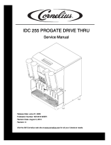
3. Refer to Figure 1 for location of hole to be drilled in the Dispenser hood for installation of the KEY-LOCK
SWITCH (item 5).
4. Place TEMPLATE, HOLE DRILLING (item 2) in position on Dispenser hood as shown in Figure 1.
5. Drill hole in Dispenser hood as indicated on the hole drilling template, then remove template from the hood.


2
569000261
1.50
TEMPLATE
(ITEM 2)
HOOD
LOCK KEY
(ITEM 3)
KEY-LOCK SWITCH
(ITEM 5)
HEX NUT
(ITEM 4)
FIGURE 1. DISPENSER HOOD
6. Install KEY-LOCK SWITCH (item 5) in the hood as shown in Figure 1 and secure with HEX NUT (item 4).
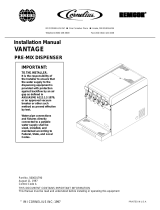
7. Refering to Wiring Diagram (Figure 2) disconnect black electrical wire, with push-on terminal on it’s end,
from terminal on the transformer outlet.
8. Connect black electrical wire, disconnected from the transformer outlet terminal, to mating electrical wire
terminal on the WIRING HARNESS (item 1).
9. Connect other electrical wire of the wiring harness to output terminal on the transformer where the black
electrical wire was disconnected from in step 7 preceding.
10. Connect other two wiring harness terminals to two terminals on the Key-Lock Switch.
11. Install hood on the Dispenser.
12. Connect electrical power to the Dispenser, then check Dispenser for proper operation.
13. Insert LOCK KEY (item 3) in key-lock switch, then check Dispenser for proper operation.
KEY-LOCK SWITCH
(ITEM 5 )
WHITE
BLACK
MATING
TERMINALS
FIGURE 2. WIRING DIAGRAM
/