Page is loading ...


The products, technical information, and instructions contained in this manual are subject to change
without notice. These instructions are not intended to cover all details or variations of the equipment,
nor to provide for every possible contingency in the installation, operation or maintenance of this
equipment. This manual assumes that the person(s) working on the equipment have been trained
and are skilled in working with electrical, plumbing, pneumatic, and mechanical equipment. It is
assumed that appropriate safety precautions are taken and that all local safety and construction
requirements are being met, in addition to the information contained in this manual.
This Product is warranted only as provided in Cornelius’ Commercial Warrant applicable to this Prod-
uct and is subject to all of the restrictions and limitations contained in the Commercial Warranty.
Cornelius will not be responsible for any repair, replacement or other service required by or loss or
damage resulting from any of the following occurrences, including but not limited to, (1) other than
normal and proper use and normal service conditions with respect to the Product, (2) improper volt-
age, (3) inadequate wiring, (4) abuse, (5) accident, (6) alteration, (7) misuse, (8) neglect, (9) unau-
thorized repair or the failure to utilize suitably qualified and trained persons to perform service and/or
repair of the Product, (10) improper cleaning, (11) failure to follow installation, operating, cleaning or
maintenance instructions, (12) use of “non-authorized” parts (i.e., parts that are not 100% compatible
with the Product) which use voids the entire warranty, (13) Product parts in contact with water or the
product dispensed which are adversely impacted by changes in liquid scale or chemical composition.
Contact Information:
To inquire about current revisions of this and other documentation or for assistance with any Corne-
lius product contact:
www.cornelius.com
800-238-3600
Trademarks and Copyrights:
This document contains proprietary information and it may not be reproduced in any way without per-
mission from Cornelius.
This document contains the original instructions for the unit described.
CORNELIUS INC
101 Regency Drive
Glendale Heights, IL
Tel: + 1 800-238-3600
Printed in U.S.A.

TABLE OF CONTENTS
Important Warnings and Advice . . . . . . . . . . . . . . . . . . . . . . . . . . . . . . . . . . . . . . . . . 1
Technical Data . . . . . . . . . . . . . . . . . . . . . . . . . . . . . . . . . . . . . . . . . . . . . . . . . . . . . . . . 1
Plate data . . . . . . . . . . . . . . . . . . . . . . . . . . . . . . . . . . . . . . . . . . . . . . . . . . . . . . . . . 1
Transportation Indications . . . . . . . . . . . . . . . . . . . . . . . . . . . . . . . . . . . . . . . . . . . . . . 1
Installation . . . . . . . . . . . . . . . . . . . . . . . . . . . . . . . . . . . . . . . . . . . . . . . . . . . . . . . . . . . 2
Connecting the Electricity Mains . . . . . . . . . . . . . . . . . . . . . . . . . . . . . . . . . . . . . . . . 2
Connection Diagrams . . . . . . . . . . . . . . . . . . . . . . . . . . . . . . . . . . . . . . . . . . . . . . . . 3
Ice Frost Generic (Pre-mix) . . . . . . . . . . . . . . . . . . . . . . . . . . . . . . . . . . . . . . . . . 3
Ice Frost Generic (Post-mix) . . . . . . . . . . . . . . . . . . . . . . . . . . . . . . . . . . . . . . . . 4
Bowl Loading Operations . . . . . . . . . . . . . . . . . . . . . . . . . . . . . . . . . . . . . . . . . . . . . 5
Ice Frost Generic (Pre-mix) . . . . . . . . . . . . . . . . . . . . . . . . . . . . . . . . . . . . . . . . . 5
Ice Frost Generic (Post-mix) . . . . . . . . . . . . . . . . . . . . . . . . . . . . . . . . . . . . . . . . 5
Brix Procedure . . . . . . . . . . . . . . . . . . . . . . . . . . . . . . . . . . . . . . . . . . . . . . . . . . . . . 6
Programming Electronic Touch Pad 2 Bowls and 2 Compressors . . . . . . . . . . . . . . 7
Program Time on Initial Installation or in the Event of Time Change . . . . . . . . . 7
Setting COLD Timer (Night Setting) . . . . . . . . . . . . . . . . . . . . . . . . . . . . . . . . . . 8
Operate in Automatic Mode (with COLD Timer Activated) . . . . . . . . . . . . . . . . . 8
Operate in Manual Mode (without COLD Timer Activated) . . . . . . . . . . . . . . . . . 8
Setting the 12 or 24 Hour Display and oF or oC Temperature Display . . . . . . . 8
Viewing the Bowl Temperature . . . . . . . . . . . . . . . . . . . . . . . . . . . . . . . . . . . . . . 9
“FILTER CLEANING” Alarm . . . . . . . . . . . . . . . . . . . . . . . . . . . . . . . . . . . . . . . . 9
“SYSTEM OVER TEMPERATURE” Alarm . . . . . . . . . . . . . . . . . . . . . . . . . . . . . 9
Programming Electronic Touch Pad 3 Bowls and 3 Compressors . . . . . . . . . . . . . 10
Program Time on Initial Installation or in the Event of Time Change . . . . . . . . 10
Setting COLD Timer (Night Setting) . . . . . . . . . . . . . . . . . . . . . . . . . . . . . . . . . 11
Operate in Automatic Mode (with COLD Timer Activated) . . . . . . . . . . . . . . . . 11
Operate in Manual Mode (without COLD Timer Activated) . . . . . . . . . . . . . . . . 11
Setting the 12 or 24 Hour Display and oF or oC Temperature Display . . . . . . 11
Viewing the Bowl Temperature . . . . . . . . . . . . . . . . . . . . . . . . . . . . . . . . . . . . . 12
Consistency Adjustment . . . . . . . . . . . . . . . . . . . . . . . . . . . . . . . . . . . . . . . . . . . . . 12
Semi-annual cleaning and sanitation or flavor change out . . . . . . . . . . . . . . . . . . 13
Special Maintenance . . . . . . . . . . . . . . . . . . . . . . . . . . . . . . . . . . . . . . . . . . . . . . . . . . 18
Restricted Air Flow Alarm . . . . . . . . . . . . . . . . . . . . . . . . . . . . . . . . . . . . . . . . . . . . 18
Electronic Monitoring . . . . . . . . . . . . . . . . . . . . . . . . . . . . . . . . . . . . . . . . . . . . . . . . . 19
Electronic Bowl Monitoring and Safety System . . . . . . . . . . . . . . . . . . . . . . . . . . . . 19
VFCB Post Mix Electronic Monitoring . . . . . . . . . . . . . . . . . . . . . . . . . . . . . . . . . . . 19
Description . . . . . . . . . . . . . . . . . . . . . . . . . . . . . . . . . . . . . . . . . . . . . . . . . . . . 19
First Filling Condition . . . . . . . . . . . . . . . . . . . . . . . . . . . . . . . . . . . . . . . . . . . . . 20
Managing Bowl Level . . . . . . . . . . . . . . . . . . . . . . . . . . . . . . . . . . . . . . . . . . . . 20
Overflow Condition . . . . . . . . . . . . . . . . . . . . . . . . . . . . . . . . . . . . . . . . . . . . . . 21
Bowl Pressure Managing . . . . . . . . . . . . . . . . . . . . . . . . . . . . . . . . . . . . . . . . . 22

VFCB Pre Mix Electronic Monitoring . . . . . . . . . . . . . . . . . . . . . . . . . . . . . . . . . . . . 23
Description . . . . . . . . . . . . . . . . . . . . . . . . . . . . . . . . . . . . . . . . . . . . . . . . . . . . 23
First Filling Condition . . . . . . . . . . . . . . . . . . . . . . . . . . . . . . . . . . . . . . . . . . . . . 24
Managing Bowl Level . . . . . . . . . . . . . . . . . . . . . . . . . . . . . . . . . . . . . . . . . . . . 24
Overflow Condition . . . . . . . . . . . . . . . . . . . . . . . . . . . . . . . . . . . . . . . . . . . . . . 25
Bowl Pressure Managing . . . . . . . . . . . . . . . . . . . . . . . . . . . . . . . . . . . . . . . . . 26
VFCB (Pre-Mix) 115V/60Hz . . . . . . . . . . . . . . . . . . . . . . . . . . . . . . . . . . . . . . . . . . 27
VFCB (Post-Mix) 115V/60Hz . . . . . . . . . . . . . . . . . . . . . . . . . . . . . . . . . . . . . . . . . 28
VFCB (Pre-Mix) 230V/50Hz . . . . . . . . . . . . . . . . . . . . . . . . . . . . . . . . . . . . . . . . . . 29
VFCB (Post-Mix) 230V/50Hz . . . . . . . . . . . . . . . . . . . . . . . . . . . . . . . . . . . . . . . . . 30
VFCB Post-Mix 115V/60H 3 Bowl . . . . . . . . . . . . . . . . . . . . . . . . . . . . . . . . . . . . . . 31
Troubleshooting . . . . . . . . . . . . . . . . . . . . . . . . . . . . . . . . . . . . . . . . . . . . . . . . . . . . . 32

Ice Frost Operator’s Manual
© 2004-2014, Cornelius Inc. - 1 - Publication Number: M620919596OPR
IMPORTANT WARNINGS AND ADVICE
This instruction manual represents an integral part of the equipment and must be kept readily available
for use.
Read the warnings contained herein carefully before installing and using this equipment.
In addition to offering information concerning routine maintenance for the Ice Frost unit and technical
back-up for troubleshooting, this manual aims to help the user make the most of the unit’s potential,
adapting it to suit the specific needs of the various countries it will be used in.
Modifications or attempts to modify the equipment will not only result in the forfeiture of the warranty, but
are also extremely dangerous.
The maintenance operations must be carried out by qualified professionals. Never attempt to repair the
unit yourselves as the intervention of non-qualified persons, as well as being hazardous, could also lead
to serious damage to the unit.
TECHNICAL DATA
PLATE DATA
The voltage and the frequency are indicated on the serial number plate, located behind the drip tray and
on the right hand side near the controls.
TRANSPORTATION INDICATIONS
To prevent the oil contained in the compressor from flowing out into the cooling circuit, the equipment
must be transported, stored, and handled in a vertical position, as per the indications given on the
packing.
The wooden pallet, with access for a fork lift, allows the packed equipment to be moved using normal
handling and hoisting means.
Unit
Number of
Bowls
Volt Hertz Amps
VFCB Post Mix 2
230 50 7.3
115 60 13.8
VFCB Pre Mix 2
230 50 7.3
115 60 13.8
VFCB Post Mix 3 115 60 21.5

Ice Frost Operator’s Manual
Publication Number: M620919596OPR - 2 - © 2004-2014, Cornelius Inc.
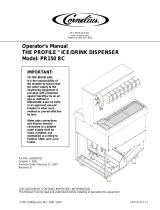
INSTALLATION
IMPORTANT: If the power supply cord is damaged, it must be replaced by qualified persons only
to prevent any possible risks.
1. Remove the equipment from the packing, then pull the
carton up (see FIGURE 1).
2. Check the unit identification after removing the packing,
you must check that the equipment you have received is
the unit you ordered, make sure the specifications
indicated on the invoice or the delivery note are identical
to those on the data plate.
3. Equipment accessories
The following accessories are included inside the bowls:
• This instruction manual;
• 1 tube of food grade lubricant to be used for the
maintenance the unit requires;
• A drip tray.
FIGURE 1
4. Positioning - make sure the unit’s bodywork is well ventilated, at least 8” on all sides, and do not
install near a heat sources.
We recommend you keep the room temperature at between 59 and 90°F.
IMPORTANT: All the pieces of packing must be kept out of reach of children as they represent
potential hazards.
CONNECTING THE ELECTRICITY MAINS
Before inserting the plug into the mains socket for your own
safety you must take careful note of the following precautions.
• The unit’s electrical system can only be considered safe
when it is connected correctly to a grounded outlet, as
provided for by the national safety regulations. The
manufacturer cannot be held responsible for any damages
that may be caused by failure to ground the system.
• For the system to be installed correctly and safely, it is
essential to provide a suitable socket which complies with
the national safety standards in force (see FIGURE 2).
FIGURE 2
• Check the power supply cable to make sure it is not being crushed. Do not use extension cords and
turn OFF the switch before removing the plug, hold the plug tightly and pull gently.
• Do not obstruct the ventilation and the heat dissipation grids, in addition to reducing the output and
causing bad functioning, could also lead to serious damage to the equipment.
Unit
VFCB Post Mix 115-60
2 Bowl
VFCB Pre Mix 115-60
2 Bowl
VFCB Post Mix 115-60
3 Bowl
VFCB Post Mix 230-50
2 Bowl
VFCB Pre Mix 230-50
2 Bowl
Plug
Nema 5-20 Nema L5-30 cs-sd or cs-sa

Ice Frost Operator’s Manual
© 2004-2014, Cornelius Inc. - 3 - Publication Number: M620919596OPR
CONNECTION DIAGRAMS
Ice Frost Generic (Pre-mix)
The diagram shows the sequence for the connection between the ICE FROST GENERIC PRE to an
existing pre-mix system.
FIGURE 3
Description:
1. Pre-mix product 1 inlet.
2. Pre-mix product 2 inlet.
4.
Inlet for CO
2
(recommended pressure 19-21 psi).
5. CO
2
gas cylinder.
6. Operating pressure gauge.
7.
CO
2
pressure regulator.
8. Gas cylinder pressure gauge.
9. Pre-mix product 1 container.
10. Pre-mix product 2 container.
11. Cooling unit (Optional).
Connection:
Connect the points 1, 2, and 4 on the unit to the existing pre-mix system using quick couplings.

Ice Frost Operator’s Manual
Publication Number: M620919596OPR - 4 - © 2004-2014, Cornelius Inc.
Ice Frost Generic (Post-mix)
The diagram shows the sequence for the connection between the ICE FROST GENERIC POST to an
existing post-mix system.
FIGURE 4
Description:
1. Syrup 1 inlet.
2. Syrup 2 inlet.
3. Soda water inlet.
4.
Inlet for CO
2
(recommended pressure 19-21 psi).
5. CO
2
gas cylinder.
6. Operating pressure regulator for carbonation unit.
7. Carbonation unit operating pressure gauge.
8. Unit operating pressure gauges.
9. Pressure regulator.
10. Gas cylinder operating pressure gauge.
11. Water Pressure regulator.
12. Filter.
13. Carbonation unit and optional precooling unit.
14. Syrup 1 pump.
15. Syrup 2 pump.
16. Bag-in-box exchanger.
17. Bag-in-box exchanger.
18. Bag-in-box.
19. BIB operating pressure gauge.
20. Pressure regulator
Connection:
Connect the points 1, 2, 3, and 4 on the unit to the existing post-mix system using quick couplings.

Ice Frost Operator’s Manual
© 2004-2014, Cornelius Inc. - 5 - Publication Number: M620919596OPR
BOWL LOADING OPERATIONS
Ice Frost Generic (Pre-mix)
• Switch the main switch to the ON position (1).
• Put the switch (A) into the ON position (1) see FIGURE 5,
switch A controls the flow of the product in the bowls.
• The bowls will now fill up until the maximum level is reached.
FIGURE 5
Ice Frost Generic (Post-mix)
• Switch the main switch to the ON position (1).
• Make sure the switch (L1) is in the OFF position (0) -
FIGURE 6 - (switch L1 controls the flow of the products in the
bowls).
• Turn mixing motors OFF immediately. Do not run unit with
bowls empty.
FIGURE 6

Ice Frost Operator’s Manual
Publication Number: M620919596OPR - 6 - © 2004-2014, Cornelius Inc.
BRIX PROCEDURE
NOTE: Prior to final installation of the 3 Bowl VFCB unit,
make a final Brix adjustment on the center bowl from the
rear of the unit.
This will be a two step process. First to adjust the water flow
rate by adjusting the water flow control and second to obtain the
proper Brix by adjusting the syrup flow control.
1. Using an 1/8 inch (8 mm) socket wrench (E1), loosen the
nut that holds the post-mix valve (D1).
2. Twist nozzle counter-clockwise (F1), lift the post-mix valve
(D1) up slightly and turn it towards the outside, leave
nozzle and coupling attached to the bowl.
3. Rotate the valve assembly 90 degrees and slide to the
outside of the unit. Tighten the 1/8 inch (8mm) nut using a
socket wrench (E1), see FIGURE 7.
4. Checking and adjusting the water flow is most easily done
by first disconnecting the syrup bib.
5. Hold the measuring cup below the valve & activate
dispense using the micro switch on the valve.
6. Adjust the water flow rate using a stop watch to 13 oz in 10
seconds (1.3 oz per second). Turn the water adjustment
screw on the flow control clockwise to increase water flow
or counter clockwise to decrease water flow.
FIGURE 7
7. Reconnect the syrup bib.
8. Dispense product into a cup by depressing the micro switch on the valve. Check Brix using a
refractometer. The Brix should be set to 13% ± 1%. To increase the Brix adjust the syrup adjustment
screw on the valve clockwise to increase syrup flow or counter clockwise to decrease syrup flow.
CAUTION: Do not turn the syrup flow control counter clockwise too far.
9. When the Brix has been set to specification, reposition the
valve to its original setting and tighten retaining nuts.
10. Repeat the operation for the second bowl and third bowl if
applicable.
Once the adjustments have been completed for each bowl,
place the switch (L1) in the ON position, see FIGURE 8.
Both bowls will fill until the level sensor is activated.
Turn mixing motors ON (switch located on the control panel).
The dispenser has built in delays for compressor and bowl fill
switch.
NOTE: During initial filling it is normal for some foaming to
take place. The bowl level management will adjust as the
product freezes & the foam will dissipate.
FIGURE 8

Ice Frost Operator’s Manual
© 2004-2014, Cornelius Inc. - 7 - Publication Number: M620919596OPR
PROGRAMMING ELECTRONIC TOUCH PAD 2 BOWLS AND 2 COMPRESSORS
Program Time on Initial Installation or in the Event of Time Change
1. Turn the power switch OFF.
2. Press and hold the left PRESS TO SELECT FUNCTION button and turn ON the power switch.
Release the PRESS TO SELECT FUNCTION button when the hour digits start blinking.
3. Set the hour by pressing the left AUTO TIMER clock button until the appropriate hour is shown.
NOTE: When using a 12 hour clock the time is P.M. when the dot at the bottom right corner of the
LED display is lit; A.M. when dot is not lit.
4. Press the left PRESS TO SELECT FUNCTION button to set the minutes, then press the left AUTO
TIMER clock button until the appropriate minutes are set.
5. Press the PRESS TO SELECT FUNCTION button one more time to save your settings.
Main Power Switch
• Turns unit ON.
• Selects 12/24 time clock or F
o
/C
o
tempera-
ture display when turned ON while simultane-
ously pressing the auger button (left).
• Sets current time when turned ON while
simultaneously pressing the PRESS TO
SELECT FUNCTION button.
Auger ON/OFF Button
• Turns auger ON and OFF when main
power switch is ON.
• Must be ON to permit COLD time to be
reset.
• Must be ON to activate the PRESS TO
SELECT FUNCTION button to select manual
OFF, FREEZE, or COLD functions.
PRESS TO SELECT FUNCTION Button
• Used to manually select OFF, FREEZE, or
COLD functions when auger is turned ON.
• Accesses COLD timer reset mode when
pressed for an extended period when auger is
turned ON.
• Does not function when light on AUTO
TIMER button is illuminated.
• Locks in hours, minutes and final time set-
tings after they are reset using the AUTO
TIMER button.
AUTO TIMER Button
• Turns auto COLD mode ON or OFF (light
on switch indicates when auto COLD mode is
activated).
• Used to adjust the hours and minutes set-
tings when readjusting current time or auto
COLD timer.
• Reset: Press and hold the AUTO TIMER
button on the left. Turn the main switch ON
and wait until “PreS” appears on the display.
FIGURE 9

Ice Frost Operator’s Manual
Publication Number: M620919596OPR - 8 - © 2004-2014, Cornelius Inc.
Setting COLD Timer (Night Setting)
1. Turn the power switch ON. Make sure the AUTO TIMER is OFF (light on button is not lit).
2. Press the left AUGER ON/OFF button ON.
3. Press and hold the left PRESS TO SELECT FUNCTION button until you hear a long beep and the
LED, COLD and the AUTO TIMER clock light begins to blink.
4. Press the left AUTO TIMER clock button to set the hour you want it to turn to COLD mode and then
press the left PRESS TO SELECT FUNCTION button to save the hour setting.
5. Press the left AUTO TIMER clock button to set the minutes to complete time setting that you want it
to turn to COLD mode. Then press the left PRESS TO SELECT FUNCTION button to save the
minute setting. The COLD light will turn OFF and the FROZEN light and AUTO TIMER light will
begin blinking.
6. Set the time you want the unit to return to FROZEN mode by following steps 1 - 5 above. Then
press the PRESS TO SELECT FUNCTION button to save the time settings for FROZEN mode.
7. Repeat steps 1 - 6 using the right buttons to set the COLD timer for the right bowl.
NOTE: Once the settings have been saved, the unit will keep the settings, even when the power
switch is turned OFF.
NOTE: When the light on the AUTO TIMER clock button is ON, the COLD timer is activated. To
turn OFF the COLD timer, press the AUTO TIMER clock button(s) until the light(s) on the clock
button(s) turns OFF.
Operate in Automatic Mode (with COLD Timer Activated)
1. Turn power switch ON and wait for LED display to light up.
2. Press the left hand AUGER ON/OFF button ON.
3. To operate in COLD mode press the AUTO TIMER button until it is illuminated.
NOTE: When setting automatic times, please keep in mind it will take time for the frozen product
to become liquid or vice versa.
4. Repeat steps 1-3 to set the right bowl using the right buttons.
Operate in Manual Mode (without COLD Timer Activated)
1. Turn the power switch ON and wait for LED display to light up.
2. Make sure the clock button is OFF (LED light on clock button should not be lit up).
3. First turn auger ON by pressing the AUGER ON/OFF button until it beeps.
NOTE: The auger must be ON before the unit will allow the COLD or FROZEN mode to be
activated.
4. Then select COLD or FROZEN mode by pressing the PRESS TO SELECT FUNCTION button until
the light under the selection you desire is lit up.
NOTE: In the COLD mode, the LED will read the actual temperature of the product (the
temperature setting is preset to NSF standards and is not adjustable.) In the FROZEN or OFF
mode the LED will read the current time.
Setting the 12 or 24 Hour Display and
o
F or
o
C Temperature Display
1. Turn the power switch OFF.
2. Press and hold the left AUGER ON/OFF button and turn ON the power switch. Release the AUGER
ON/OFF button when either “12” or “24” are shown (indicates the current hour view).
3. Press the AUTO TIMER button until the desired hour display type is shown (12 or 24).
4. Press the PRESS TO SELECT FUNCTION button until either
o
F or
o
C is shown on the display.
5. Press the AUTO TIMER button until the desired temperature display type is shown (
o
F or
o
C).
6. Store the change by pressing the PRESS TO SELECT FUNCTION button until the current time is
displayed. The unit is now ready for use.

Ice Frost Operator’s Manual
© 2004-2014, Cornelius Inc. - 9 - Publication Number: M620919596OPR
Viewing the Bowl Temperature
1. Press the PRESS TO SELECT FUNCTION button until the COLD LED is lit. The display will now
show the current bowl temperature in either
o
F or
o
C as applicable.
2. Turn ON the auger on the side that you want to display the bowl temperature (press the AUGER
ON/OFF button).
“FILTER CLEANING” Alarm
A filter cleaning alarm will activate when the unit is running hot due to insufficient internal air circulation.
When this occurs a “Filtr” message will appear on the touch pad LED display readout and an intermittent
tone will also sound to alert the operator of this condition.
The “Filtr” message will appear when the alarm activates (a beeping sound every 4-5 seconds). To
determine the condition that caused the alarm and correct problem, see list of conditions below:
“SYSTEM OVER TEMPERATURE” Alarm
A system over temperature alarm will activate as a safety precaution when the unit has overheated to
protect the compressor.
• The system automatically goes to “OFF” status where the compressor’s operations is stopped, while
augers will keep working to avoid forming ice blocks.
• When this occurs an “Err” message will appear on the touch pad LED readout accompanied by a
continuous buzzer sound to alert the operator of this condition.
• When this alarm sounds, turn OFF all switches. Then determine the reason for the alarm. (See “Filter
Cleaning” Alarm Section for Conditions and Corrective Actions).
Condition Corrective Action
• The filter is dirty and needs to be cleaned. • Clean and replace filter following instructions
(Removing and Cleaning Filter).
• The unit is positioned too close to a wall or
other object restricting air flow and causing
the unit to run at a higher temperature.
• Reposition unit to maximize ventilation space
(Installation Instructions).
• The filter is not properly installed. • Properly install filter (Removing and cleaning fil-
ter).
• The unit has been installed near a heat
source, such as a coffee machine, ice maker
or cold beverage machine which expels hot
air from its vents, causing the unit to run at a
high temperature (installation near a heat
source should be avoided).
• Reposition unit to maximize ventilation space.

Ice Frost Operator’s Manual
Publication Number: M620919596OPR - 10 - © 2004-2014, Cornelius Inc.
PROGRAMMING ELECTRONIC TOUCH PAD 3 BOWLS AND 3 COMPRESSORS
Program Time on Initial Installation or in the Event of Time Change
1. Turn the power switch OFF.
2. Press and hold the left MODE button and turn ON the power switch. Release the MODE button
when the hour digits start blinking.
3. Set the hour by pressing the Auto Timer clock button until the appropriate hour is shown.
NOTE: When using a 12 hour clock the time is P.M. when the dot at the bottom right corner of the
LED display is lit; A.M. when dot is not lit.
4. Press the left MODE button to set the minutes, then press the Auto Timer clock button until the
appropriate minutes are set.
5. Press the MODE button one more time to save your settings.
Main Power Switch
• Turns unit ON.
• Selects 12/24 time or F
o
/C
o
temperature
display when turned ON while simultane-
ously depressing the Auger button (left).
• Sets current time when turned ON while
simultaneously pressing the left MODE but-
ton.
Auger ON/OFF Button
• Turns auger ON and OFF when main
power switch is ON.
• Must be ON to permit COLD time to be
reset.
• Must be ON to activate the MODE button to
select manual OFF, FREEZE, or COLD func-
tions.
MODE Button
• Used to manually select OFF, FREEZE, or
COLD functions when auger is turned ON.
• Accesses COLD timer reset mode when
pressed for an extended period when auger is
turned ON.
• Does not function when light on Auto Timer
button is illuminated.
• Locks in hours, minutes and final time set-
tings after they are reset using the Auto Timer
button.
Auto Timer Button
• Turns auto COLD mode ON or OFF (light
on switch indicates when auto COLD mode is
activated).
• Used to adjust the hours and minutes set-
tings when adjusting current time or auto
COLD timer.
• Reset: Press and hold the Auto Timer but-
ton on the left. Turn the main switch ON and
wait until “PreS” appears on the display.
FIGURE 10
Bowl Temperature
Button
In defrost condition
this shows the product
temperature inside the
bowl.

Ice Frost Operator’s Manual
© 2004-2014, Cornelius Inc. - 11 - Publication Number: M620919596OPR
Setting COLD Timer (Night Setting)
1. Turn the power switch ON. Make sure the Auto Timer is OFF (light on button is not lit).
2. Press the left Auger ON/OFF button ON.
3. Press and hold the left MODE button until you hear a long beep and the LED, Cold and the Auto
Timer clock light begins to blink.
4. Press the Auto Timer clock button to set the hour you want it to turn to COLD mode and then press
the MODE button to save the hour setting.
5. Press the Auto Timer clock button to set the minutes to complete time setting that you want it to turn
to COLD mode. Then press the left MODE button to save the minute setting. The COLD light will
turn OFF and the FROZEN light and Auto Timer light will begin blinking.
6. Set the time you want the unit to return to FROZEN mode by following steps 1 - 5 above. Then
press the left MODE button to save the time settings for FROZEN mode.
NOTE: Once the settings have been saved, the unit will keep the settings, even when the power
switch is turned OFF.
NOTE: When the light on the Auto Timer clock button is ON, the COLD timer is activated. To turn
OFF the COLD timer, press the Auto Timer clock button(s) until the light(s) on the clock button(s)
turns OFF.
Operate in Automatic Mode (with COLD Timer Activated)
1. Turn power switch ON and wait for LED display to light up.
2. Press the left hand Auger ON/OFF button ON.
3. To operate in COLD mode press the Auto Timer button until it is illuminated.
NOTE: When setting automatic times, please keep in mind it will take time for the frozen product
to become liquid or vice versa.
NOTE: The COLD timer is the same for all the bowls. The COLD mode can be activated only if at
least one Auger button is ON.
Operate in Manual Mode (without COLD Timer Activated)
1. Turn the power switch ON and wait for LED display to light up.
2. Make sure the clock button is OFF (LED light on clock button should not be lit up).
3. First turn auger ON by pressing the Auger ON/OFF button until it beeps.
NOTE: The auger must be ON before the unit will allow the COLD or FROZEN mode to be
activated.
4. Then select COLD or FROZEN mode by pressing the MODE button until the light under the
selection you desire is lit up.
NOTE: In the COLD mode, the LED will read the actual temperature of the product (the
temperature setting is preset to NSF standards and is not adjustable.) Pushing the Thermometer
button allows you to see the temperature in the left bowl (LED1 lit) or right bowl (LED 2 lit). In the
FROZEN or OFF mode the LED will read the current time.
Setting the 12 or 24 Hour Display and
o
F or
o
C Temperature Display
1. Turn the power switch OFF.
2. Press and hold the left Auger ON/OFF button and turn ON the power switch. Release the Auger
ON/OFF button when either “12” or “24” are shown (indicates the current hour view).
3. Press the Auto Timer button until the desired hour display type is shown (12 or 24).
4. Press the left MODE button until either
o
F or
o
C is shown on the display.
5. Press the Auto Timer button until the desired temperature display type is shown (
o
F or
o
C).
6. Store the change by pressing the left MODE button until the current time is displayed. The unit is
now ready for use.

Ice Frost Operator’s Manual
Publication Number: M620919596OPR - 12 - © 2004-2014, Cornelius Inc.
Viewing the Bowl Temperature
1. Press the left MODE button until the COLD LED is lit, than press the Bowl Temperature button. The
display will now show the current bowl temperature in either
o
F or
o
C, as applicable.
2. Turn ON the auger on the side that you want to display the bowl temperature (press the Auger ON/
OFF button).
CONSISTENCY ADJUSTMENT
1. To dispense the product, place the cup beneath the
dispensing valve (Q) and pull the lever (R) very gently
(FIGURE 11).
2. Adjusting the viscosity:
To vary the viscosity of the product, turn the knob (S) as
shown in FIGURE 12.
Turning the knob counter-clockwise will increase viscosity
(make the product more dense).
Turning the knob clockwise will decrease viscosity (make the
product less dense).
FIGURE 11
ATTENTION: This control only changes the viscosity of the
product dispensed, it does not effect the COLD
temperature.
ATTENTION: When the level of the product inside the bowl
is below the minimum level, to stop the product from
becoming too dense, you must switch the COLD system
(OFF position) or refill the bowl.
An indicator gauge for reference is located on the back of the
unit approximately 6 inches below the adjustment knob.
FIGURE 12

Ice Frost Operator’s Manual
© 2004-2014, Cornelius Inc. - 13 - Publication Number: M620919596OPR
SEMI-ANNUAL CLEANING AND SANITATION OR
FLAVOR CHANGE OUT
Perform this cleaning procedure once every 6 months.
NOTE: Cleaning and sanitizing intervals depend on the products used in the unit. Six month
cleaning is the standard time for most products. If the product contains dairy, for example, a more
frequent cleaning schedule may be necessary. Please contact service if you have any questions
about the cleaning interval on the product you are using.
ATTENTION: The unit must be disconnected from the power supply before disassembling the unit
for cleaning.
NOTE: During the cleaning and sanitizing procedure it is advised to Brix the valves to ensure
accuracy. Follow the procedure on page 6.
1. Remove the cover (B) FIGURE 13.
FIGURE 13
2. Turn the switch (L1 in FIGURE 6) to the OFF position (0).
3. Press the mode or select function button on the touch pad to the OFF position. (This will stop
refrigeration).
4. Empty the bowl of any remaining product.
5. Remove all the quick disconnects from the BIB container.
6. Fill a suitable bucket with soap solution.
7. Submerge all disconnects in the soap solution and then clean them using a nylon bristle brush. (Do
not use a wire brush). Rinse with clean water.
8. Using a bucket, prepare approximately 2.5 gallons of sanitizing solution.
9. Rinse the BIB disconnects in the sanitizing solution.
10. Sanitizing fittings must be attached to each BIB disconnect. If these fittings are not available, the
fittings from empty BIB bags can be cut from the bags and used. These fittings open the disconnect
so the sanitizing solution can be drawn through the disconnect.
11. Place all the BIB disconnects into the bucket of sanitizing solution.
12. Turn the switch (L1 in FIGURE 6) to the ON position (1). This will start flushing the syrup line with
sanitizer.
13. Keep emptying the bowl until the incoming product runs clear.
14. Turn the switch (L1 in FIGURE 6) to the OFF position (0).
15. Allow the sanitizer to remain in the lines for fifteen (15) minutes.
16. Connect the BIB disconnect to the appropriate BIB container.
17. Turn the switch (L1 in FIGURE 6) to the ON position (1). This will start flushing the sanitizer out of
the line and re-fill with syrup.
18. Keep emptying the bowl until the incoming syrup is flowing freely for approximately thirty (30)
seconds.
19. Turn the switch (L1 in FIGURE 6) to the OFF position (0).
20. Empty the bowl of any remaining product and switch OFF the main switch.

Ice Frost Operator’s Manual
Publication Number: M620919596OPR - 14 - © 2004-2014, Cornelius Inc.
21. Extract the quick couplings (C2) / (F2) - (FIGURE 14, FIGURE 15, and FIGURE 16).
22. Disconnect the probe fastenings (D2) / (E2) - (FIGURE 14 and FIGURE 15).
FIGURE 14. Pre-Mix Version
FIGURE 15. Post-Mix Version
FIGURE 16
23. Pull the lockpin/safety pin (Y) upwards - FIGURE
17.
FIGURE 17
24. Slide the locking bar (Z) - FIGURE 18 - outwards so
that the bowls are fully released.
Unlock relief valve on the bowl lid cap and remove
(FIGURE 19).
FIGURE 18

Ice Frost Operator’s Manual
© 2004-2014, Cornelius Inc. - 15 - Publication Number: M620919596OPR
25. Unscrew the knobs (A1) so the bowls can be
lowered slightly, open the tap to remove any
remaining liquids and then extract it from its seating,
pulling it outwards (FIGURE 19).
FIGURE 19
26. Remove the tap from its seating, press the two
clamping wings at the same time (FIGURE 20) and
push upwards.
FIGURE 20
27. Remove the tap, holding the body (R) pressed
downwards, then slide the lever (L) out of its seating
(FIGURE 21). Wash all the parts thoroughly with hot
water and mild detergent, rinse them well, and
replace them.
FIGURE 21
28. Separate the bowl from the cover, releasing the
fastening (D1) by pulling them upwards, as shown
in FIGURE 22.
FIGURE 22
Bowl Lid Cap

Ice Frost Operator’s Manual
Publication Number: M620919596OPR - 16 - © 2004-2014, Cornelius Inc.
29. Wash the bowl and cover carefully with water and
mild detergent, rinse them well, and replace them,
making sure the sealing strip (E1) is positioned
correctly between the cover and the bowl. To
guarantee the seal, the rounded part of the sealing
strip (as shown in FIGURE 23) must be facing the
cover.
FIGURE 23
30. Unscrew the fastening knob (F1) clockwise as the
direction indicated by the arrow (threading to the
left) and remove the spiral scraper (G1) and the
seals (H1) and (I1). Clean the individual parts
thoroughly (FIGURE 24).
FIGURE 24
31. Clean the drip tray (J1) and the evaporator (K1)
(FIGURE 25).
32. Replace the mixing unit as follows:
• Dampen the sealing strip (l1) and insert it into its
seating.
• Apply a generous amount of food grade lubricant
(supplied with the unit) to the suction cup seal
(H1) (on the part that comes into contact with the
evaporator K1) and insert it in its spiral seating.
• Replace the spiral scraper (G1).
• Fasten all the components in place by screwing
the knob F1 counter-clockwise.
FIGURE 25
33. Replace the bowl by pushing it into its seating.
34. Fasten the bowl in place by tightening the knobs
(A1) - FIGURE 26 and the locking bar (Z) - FIGURE
18. Reverse steps 3 and 4.
FIGURE 26
/