Page is loading ...

HM ELECTRONICS, INC.
14110 Stowe Drive, Poway, CA 92064 USA • Phone: 1-800-848-4468 Fax: (858) 552-0172
HME# 400G575
Rev − 1027/05
VDB102
Vehicle Detector Board
INSTALLATION INSTRUCTIONS
IMPORTANT!
⎯ When handling the VDB102, use proper grounding procedures to
avoid electrical damage to the board.
1. INSTALLATION
• Disconnect the drive-thru audio or timer system power adapter from its
electrical outlet.
• If the VDB102 will replace an existing VDB101, do 1, 2 and 3 below. If not, skip
them and go on to the following step.
1. Disconnect the loop cable from TB1 on the VDB101.
2. Disconnect the VDB101 interconnect cable from its connector on the base
station or control unit circuit board. Note the connector and its location.
3. Remove the VDB101 by lifting it off the plastic standoffs that hold it in place.
• Position the VDB102 over the three plastic standoffs on the base station or
control unit circuit board and press it firmly until the standoffs snap through
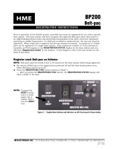
the holes on the VDB102. See Figure 1.
• Connect the loop cable to TB1 at the lower right corner of the VDB102. See
Figure 1.
• Connect the VDB102 interconnect cable to P1, at the upper left corner of the
VDB102. See Figure 1. Be certain the plastic catches on the cable connector are
aligned with the plastic catches on the P1 connector. The color-coded connector wires
must also match the pin positions shown on Figure 1, below. Connect the other end
of the interconnect cable to the circuit board in the base station or control unit
according to installation instructions from the drive-thru audio or timer system.
If the installation instructions are not available, call HME at 1-800-848-4468.
• Reconnect the drive-thru or timer system power adapter to its electrical outlet.
• Be certain the LED on the VDB102 is lit when a vehicle is on the loop. If it is not, be
certain all connections are tight. If it is still not lit, call HME at 1-800-848-4468.
If it is necessary to change the functions of the VDB102, refer to the DIP switch
settings on the back of this sheet. Normally, no changes will be required.
Figure 1. VDB102 Vehicle Detector Board
P1 Pins:
1 (shield) – GND
2 (red) - +12VDC
3 (black) – Output/Sig
NOTE:
Adjust switches as needed
before installing the
VDB102. See back page
for switch settings.
Plastic
standoffs
LED
Loop
connector
Plastic
standoff

2. DIP SWITCH SETTINGS
Before installing the VDB102, the following six functions
can be set by switching/moving the switches as indicated
in tables A through F below. Refer to Figure 2.
* = factory setting
Switch #1 Vehicle Presence Auto Reset
Switch #5 Vehicle Present Switching Test
OFF None
OFF Diagnostic off, normal operation *
ON 20 minute *
ON Diagnostic on, 10 sec on, 10 sec off
Switch #2 Turn-On Sensitivity
Switch #6 Switch #7 Output Delay
OFF Normal (2 Hz) *
OFF OFF 6 second
ON Reduced (3 Hz)
ON OFF 4 second
OFF ON 2 second
Switch #3 Switch #4 Turn-Off Threshold
ON ON None *
OFF OFF Extra Low (15%)
ON OFF Low (25%)
Switch #8 Output Pulse
OFF ON Normal (35%) *
OFF 0.5 second
ON ON High (40%)
ON Steady (no pulse) *
3. SELF DIAGNOSTICS
If an abnormal condition with the
loop or oscillator occurs, the LED
will indicate one of the following
conditions. There is no Vehicle-
Present signal generated during
the self diagnostics.
4. RESET PROCEDURE
With no vehicle present over the vehicle detector loop, press the reset switch in the
base station or timer for 1 second, or unplug the power cable for 1 second. The LED
will go on for 3 seconds. Reset is completed when the LED goes off.
5. TROUBLESHOOTING
Turn-On Sensitivity:
• Set to Reduced (3Hz) to help prevent false turn-on when the frequency drifts or
varies due to a bad loop.
Turn-Off Threshold:
• Set to High (40%) if run-on between cars occurs at Normal (35%).
• Set to Extra Low (15%) or Low (25%) to compensate for improperly positioned loops.
• Set for highest percentage possible. Check for run-on or dropouts and set for
best operation.
Problem LED Blink Rate
No oscillator (<2 KHz) 1 blink and a pause
Open loop (<10 KHz) 2 blinks and a pause
Out of range (10-20 KHz) 3 blinks and a pause
Shorted loop (>75 KHz) 4 blinks and a pause
Figure 2. S1 DIP switch
on VDB102 circuit board
This equipment has been tested and found to comply with the limits for a Class A digital device, pursuant to Part 15 of the FCC
Rules. These limits are designed to provide reasonable protection against harmful interference when the equipment is operated
in a commercial environment. This equipment generates, uses, and can radiate radio frequency energy and, if not installed and
used in accordance with the instruction manual, may cause harmful interference to radio communications. Operation of this
equipment in a residential area is likely to cause harmful interference in which case the user will be required to correct the
interference at his own expense.
/