REDBACK Stereo Amplifiers
Page 2
Overview:
These compact, stylish, high performance, high fidelity
amplifiers can function as individual stand alone
amplifiers or a high performance stereo amplifier. Both
channels can be configured to operate in “bridge
mode”(mono) providing a massive 550W RMS power to
an 8 ohm load (model A 4150).
Incorporates a multi-staged thermally cued fan forced
cooling system. Output stages are continually thermally
monitored enabling automatic operation of a long life
computer style cooling fan to “off” , “low” or “high” air
flow through the custom designed tunnel heatsink. In
quiescent and low level operation the fans are inoperative.
Over temperature sensing is employed to shut down the
amplifiers in high temperature conditions, eg extreme
overload and/or overdrive mis-use. Re-start is automatic
once normal temperatures are attained.
The circuitry employed in the design protects the integrity
of the amplifiers under the following conditions: over
temperature, overload. The circuit even protects itself
under short circuit conditions. Each channel includes its
own front mounted volume control, recessed treble & bass
control and VU metering. On the rear, each channel
includes combination XLR / 6.35mm phono jacks for
inputs, heavy duty binding posts and Speakon
®
style
speaker connectors. In bridge mode operation, only one
volume control remains active.
Visual indication for each channel includes power on,
fault, clip, signal presence and output VU. The speaker
outputs are relay to prevent damage to the connected
speakers in case of a catastrophic failure. The relays
provide silent operation when amplifier is powered on or
off.
Features:
• Bridge mode capability
• Independent treble, bass and volume for each channel
• Silent de-thump start up and shut down
• Multi-Stage thermally cued cooling
• LED Bargraph VU meter
• Input signal presence indicator
• 2U 19" rack mount
• Thermal, overload and short circuit protection
• Australian designed and assembled
• 2 Year warranty
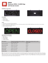
Operation:
Using RCA input: Plug the selected source (eg: DVD, CD,
Tuner) directly into the RCA sockets. Ensure the input
selection switch is set to RCA position.
Adjust front panel volume controls to desired level. Adjust
treble and bass for each channel as desired.
Using XLR/6.5mm input: Plug the selected source directly
into the XLR/6.5mm jack sockets. Ensure the input
selection switch is set to correct position.
Adjust front panel volume controls to desired level. Adjust
treble and bass for each channel as desired.
Once signal is applied the “signal present” LED will
illuminate on the front panel.
Speakers: Connect appropriately rated speakers to either
the binding post output or the speaker connector for each
channel. Speaker load should be between 4-8Ω. The output
will operate into 2 ohms but if the amplifier is driven hard,
the overload protection is likley to activate.
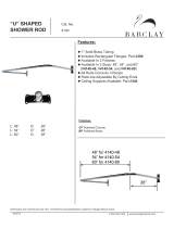
BCD I J KE F G H
LEGEND
1. IEC 240V Mains Connection ( with built in fuse)
2. Output channel 2 (speaker connector)
3. Output channel 2 (binding post)
4. Output channel 1 (binding post)
5. Output channel 1 (speaker connector)
6. Input selector (RCA or XLR)
7. Input channel 2 (XLR/6.5mm combination socket)
8. Bridged mode switch (on/off)
9. Input channel 1 (XLR/6.5mm combination socket)
10. RCA inputs (channel 1 & 2)
Channel 1 Channel 2
Channel 2 Channel 1