Page is loading ...

A 4154 2 x 100W
A 4156 2 x 200W
A 4158 2 x 300W
www.altronics.com.au
Stereo Power Amplifiers
OPERATING INSTRUCTIONS
Distributed by Altronic Distributors Pty. Ltd. Perth.
Western Australia.
Phone: 1300 780 999 Fax: 1300 790 999
Internet: www.altronics.com.au
Overview:
The A 4154, A 4156, and A 4158 series of amplifiers
are a cost effective solution for demanding
commercial audio applications. These non-bridgeable
models are designed to be used as standard 2 channel
or stereo amplifiers. The design incorporates a fan
forced cooling system to ensure reliability under the
most intense output drive conditions.
The protection circuitry employed in the design
ensures the integrity of the amplifiers under overload
conditions. The circuit even protects the amp when a
total short circuit is applied across the output
terminals. The 'soft start' limiter will immediately
shut down the output drive in overload or short
circuit conditions, then gradually restart when the
fault condition has been removed.
Each channel includes its own recessed front panel
mounted volume control and standard rear panel
mounted RCA & 6.35mm input jacks. Output
connections are made via heavy duty binding posts,
industry standard heavy duty speaker connectors, or
6.35mm Jacks.
Features:
• High Power output.
• Rugged heavy duty construction
• 19" rack mount, with removeable rack ears
• Stylish cosmetics
• Soft start limiter
• Earth lift switch
• Limiter on/off switch
• RCA & 6.35mm jack inputs
• Binding post & industry standard heavy duty
output speaker connectors
• Clipping & overload/overdrive protect indicators
• Recessed detent volume controls for each channel
• Thermally cued fan forced cooling
• 1 Year Warranty

Stereo Power Amplifiers
Page 2
B
CD I J
K
L
EF H
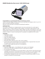
REAR PANEL LEGEND
1. Channel B input 6.35mm jack
2. Stereo RCA inputs for channel A and B
3. Channel A input 6.35mm jack
4. Lift / Ground switch
5. Channel B output 6.35mm
6. Channel B output binding post
7. Channel A output binding post
8. Channel A output 6.35mm
9. 240V Mains Input
10. Channel B output H/D speaker connector
11. Channel A output H/D speaker connector
G
ClipProt
ON
Clip
BCEFH
FRONT PANEL LEGEND
1. Power Switch
2. Power LED
3. Protection LED
4. Channel A clip LED
5. Channel A level control
6. Channel B clip LED
7. Channel B level control
GD
Front panel:
1. Power ON/OFF. When switched ON, Soft start
will protect the speaker load from spikes.
2. Power LED (Blue). LED will light when 240VAC is
connected and POWER switch is ON.
3. Protect LED (Orange). This LED will light under
any one of the following three conditions:
a. At power ON, whilst soft start is active. Soft start
will take approx 3-5 seconds.
b. If the output stage reaches 85deg C due to
overload condition.
c. Power supply failure.
4. and 6. Channel A and channel B clip LED’s (Red).
These LED’s will light under two different
conditions:
a. When maximum output is achieved
b. If a short circuit condition exists across the
amplifier outputs.
5. Channel A level control.
7. Channel B level control.
Rear Panel:
1. Channel B input. 6.35mm mono jack.
2. Stereo RCA inputs for Channels A and B
3. Channel A input. 6.35mm mono jack.
4. Lift / Ground Switch. This switch is used to help
isolate ground loops or hum.
5. 6. and 10. Channel B output. Heavy duty speaker
connector, binding posts, and 6.35mm Jack.
7. 8. and 11. Channel A output. Heavy duty speaker
connector, binding posts, and 6.35mm Jack.
9. Mains power input. IEC socket with fuseholder.
240V AC Mains
Ground
Lift
OUTPUTS INPUTS

Stereo Power Amplifiers
Page 3
NOTE: Ensure that the amplifier is not continually
driven into clipping. Prolonged use in the clip mode
could cause permanent damage to connected speakers.
Volume controls should be adjusted so the “clip”
LED’s rarely illuminate.
Trouble Shooting
If amplifier fails to deliver the rated performance, see
below:
NO POWER
(Power LED light does not illuminate) Check mains fuse.
Only replace with the correct fuse, as stated on the rear
panel of the amplifier.
DISTORTED OUTPUT
Check that the speaker type is correct for the output that you are using. Measure speaker impedance.
DO NOT CONNECT 100V LINE SPEAKERS TO THIS AMPLIFIER
VERY LOW OUTPUT
Make sure that the input is the correct level (check for shorted connectors). Check for any short circuits on the
speaker line.
AMPLIFIER KEEPS ON CUTTING IN & OUT
Make sure that there is adequate ventilation around the amplifier. Ensure the vent slots on the case are not
covered or blocked. Check also the speaker types, ratings and for any short circuits on the speaker line.
PROTECTION LED LIGHT ILLUMINATES
Make sure that there is adequate ventilation around the amplifier. Ensure the vent slots on the case are not
covered or blocked. Check also the speaker types, ratings and for any short circuits on the speaker line.
SPECIFICATIONS
*Specifications subject to change without notice
POWER OUTPUT
A 4154
100W RMS into 8Ω per channel
170W RMS into 4Ω per channel
A 4156
200W RMS into 8Ω per channel
350W RMS into 4Ω per channel
A 4158
300W RMS into 8Ω per channel
450W RMS into 4Ω per channel
Distortion: ........................................................................................≈0.04%
Frequency response: ..............................................10Hz - 50kHz, -1.5dB
Speaker outputs: ............................................................................4 – 8Ω.
Input Sensitivity: ................................................................................0.77V
Signal to noise ratio: ........................................................................>90dB
OUTPUT CONNECTORS
Speakers: ............Binding posts, 4 pin Heavy duty speaker connectors,
6.35mm Jacks.
INPUT CONNECTORS
Inputs: ................................................6.35mm jacks, or RCA connectors.
240V AC power: ......................................................IEC power connector
CONTROLS
Volume: ..................................................................Channel 1, Channel 2
Power: ..................................................................................On/off switch
Indicators: ................................................................Power, Protect, Clip.
Power supply: ..............................................................................240V AC
Fuse protection:
A 4154: ..........5A 250V Fast Blow
A 4156: ..........8A 250V Fast Blow
A 4158: ........10A 250V Fast Blow
Weight:
A 4154: ................................9.5Kg
A 4156: ..............................11.5Kg
A 4159: ................................13Kg
Dimensions: ..................................430 W X 300 D X 85 H (standard 2U)
Colour: ..............................................................................................Black
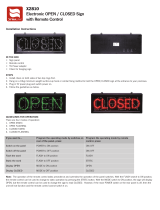
+
+
+
4Ω Min
Stereo
(Binding Post)
+
4Ω Min
Channel 1
Channel 2
+
+
+
4Ω Min
Pin 1+
Stereo
(Speaker Connector)
Pin 1-
+
Pin 1+
Pin 1-
4Ω Min
Channel 1
Channel 2
Connect to binding post or speaker connectors as desired. Ensure
load is correct. 4Ω minimum.
/