Page is loading ...

Instruction & Operation Manual
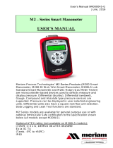
DVR
Digital
Vacuum
Regulator


i
CC
CC
C
ANNONANNON
ANNONANNON
ANNON
®
Digital Vacuum Regulator Instruction & Operation Manual
Version 1.3 — May, 2009; CANNON
®
Instrument Company
2139 High Tech Road • State College, PA • 16803 • USA
CONTENTS
1
DVR INTRODUCTION 1
Overview ............................................................................................................................ 1
Product specifications......................................................................................................... 2
2
UNPACKING THE DVR 3
Safety warnings .................................................................................................................. 3
3
INITIAL SETUP 5
Tubing connections............................................................................................................. 5
DVR-1000 connections .......................................................................................... 5
DVR-1500 connections .......................................................................................... 6
Vacuum trap............................................................................................................ 6
Electrical connections......................................................................................................... 7
4
DVR OPERATION 9
Default settings................................................................................................................... 9
Accessories ......................................................................................................................... 9
Turning on the DVR ........................................................................................................... 9
Meter Display/key control options ..................................................................................... 9
Selecting a channel ................................................................................................. 9
Adjusting the flow rate ..................................................................................................... 10
Bleeding vacuum .............................................................................................................. 11
Adjusting control set points.............................................................................................. 11
Adjusting HI/LO set points .............................................................................................. 12

ii
CC
CC
C
ANNONANNON
ANNONANNON
ANNON
®
Digital Vacuum Regulator Instruction & Operation Manual
Version 1.3 — May, 2009; CANNON
®
Instrument Company
2139 High Tech Road • State College, PA • 16803 • USA
5
DVR CLEANING AND MAINTENANCE 13
Cleaning............................................................................................................................ 13
Maintenance .....................................................................................................................13
Troubleshooting the DVR .................................................................................... 13
6
WARRANTY/RETURN INFORMATION 15
Products limited warranty................................................................................................. 15
Reagent and chemical warranty........................................................................................ 15
Returning a product to CANNON
®
.................................................................................. 16
A
APPENDIX A — REPLACEMENT PARTS 17
B
APPENDIX B — CALIBRATION OF THE SETRA GAUGE 19
Removing the differential gauge from the DVR .................................................. 20
Reassembling the DVR unit ................................................................................. 21

1
CC
CC
C
ANNONANNON
ANNONANNON
ANNON
®
Digital Vacuum Regulator Instruction & Operation Manual
Version 1.3 — May, 2009; CANNON
®
Instrument Company
2139 High Tech Road • State College, PA • 16803 • USA
CHAPTER
1
DVR INTRODUCTION
Overview
Purpose of the manual
This manual provides information on the installation and operation of
your DVR 1000 Series Digital Vacuum Regulator (DVR). The informa-
tion provided is applicable to all DVR Series instruments listed in the
table on page two.
DVR function
Your CANNON
®
DVR 1000 Series instrument has been designed to
regulate vacuum at 300 mm Hg below atmospheric pressure. Vacuum may
be adjusted to other settings from 28 to 411 mm Hg. The DVR may be
used with all CANNON
®
temperature baths including the CT and TE
Series high and low temperature instruments.
Applications
Your DVR may be used in conjunction with the Cannon-Manning cali-
brated CMVC series viscometers, the Modified Koppers Calibrated
MKVC Series viscometers, and the Asphalt Institute Vacuum Calibrated
AIVC series viscometers for measurement of highly viscous materials
such as asphalt cement at 60°C (140°F) per ASTM D 2171 specifications.
Both the Cannon-Manning and the Modified Koppers permit viscosity
measurement from 42 to 200,000 poise. The Asphalt Institute AIVC
Series 400R and 800R viscom-
eters, also available from
CANNON
®
, extend that range
to 1,400,000 poise and
5,800,000 poise respectively
(see ASTM D 2171, Table X2).
Your DVR is also useful in other
laboratory systems where
accurate measurement and
control of vacuum from 28 to
330 mm Hg below atmospheric
pressure is required.
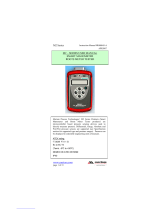
Series differences
The DVR-1000 is designed to
regulate the user’s in-house
vacuum system.
The DVR-1500 includes an
internal vacuum pump and does
not require in-house vacuum.
Digital Vacuum Regulator
with
CANNON
®
CT-1000
Constant Temperature Bath

2
CC
CC
C
ANNONANNON
ANNONANNON
ANNON
®
Digital Vacuum Regulator Instruction & Operation Manual
Version 1.3 — May, 2009; CANNON
®
Instrument Company
2139 High Tech Road • State College, PA • 16803 • USA
Configuration options
The DVR is available from CANNON
®
in both horizontal and vertical
configurations. With its sturdy steel construction, the horizontal DVR
unit will support any CANNON
®
CT or TE Series temperature bath. The
vertical configuration offers convenience in locations where work space
is at a premium.
Product specifications
snoitacificepSseireS0001RVD
tnemurtsnI 0001RVD 0051RVD
snoisnemiD )ni95.81x19.6x5.81(mm274x571x074
thgieW )sbl05(gk32)sbl35(gk42
tnioPgnitarepO gHmm5.0±003
elbadnapxE
egnar
gHmm033ot82morflortnocetaruccA
yalpsiD gHmm033-0
gnidaeR
ycarucca
elacslluffotnecrep50.0±taelbaecartdnadeifitrecTSIN
tigidtnacifingistsaeleht±
,ytilibatae
per,ytiraenilfostceffedenibmocsedulcni(
)erutarepmetdnasiseretsyh
lanoitarepORVD
erutarepmet
)F°501-23(C°04ot0
muucaV.xaM
)deilppus-resufi(
erusserpcirehpsomtawolebgHmm05±065
muucaV.niM
)deilppus-resufi(
erusserpcirehpsomtawolebgHmm023
muucaV
noitcennoc
tinuforaertadaehklubdemorhc,TPNelamef"8/1
gnitarepO
tnemnorivnE
,gnisnednoC-noNHR%09ot01,C°03-01
2eergeDnoitulloP,IIyrogetaCnoitallatsnI
esuF
tnemecalpeR
"¼x¼1;V052A2M
ecnailpmoC egatlovwoL,)CEE/633/98(evitceridCME
).ces06,CDV0091(TOP-IH,)CEE/32/37(evitcerid
/rebmuNgolataC
lacirtcelE
stnemeriuqeR
fotnecrep01±(
)egatlov
)latnoziroh(02T-6279
sttaw571,zH06/05,V511
)la
citrev(52T-6279
sttaw571,zH06/05,V511
)latnoziroh(06T-6279
sttaw571,zH06/05,V511
)lacitrev(56T-6279
sttaw571,zH06/05,V511
)latnoziroh(32T-6279
sttaw571,zH05,V032
)lacitrev(72T-6279
sttaw571,zH05,V032
)latnoziroh(
36T-6279
sttaw571,zH05,V032
)lacitrev(76T-6279
sttaw571,zH05,V032

3
CC
CC
C
ANNONANNON
ANNONANNON
ANNON
®
Digital Vacuum Regulator Instruction & Operation Manual
Version 1.3 — May, 2009; CANNON
®
Instrument Company
2139 High Tech Road • State College, PA • 16803 • USA
CHAPTER
2
UNPACKING THE DVR
Unpacking procedure
1. Remove all components from the shipping container(s).
2. Remove any and all packing materials (styrofoam, etc.) from the
components.
3. Verify reception of shipped materials by comparing equipment items
with packing/parts list(s). Report missing items to CANNON
®
Instrument Company immediately.
4. Inspect each component for signs of damage. Report damages to the
shipper and to the CANNON
®
Instrument Company immediately.
Damaged items
Retain all packing materials until the instrument is connected and func-
tioning properly. If any component(s) must be returned to
CANNON
®
Instrument Company, the damaged item(s) should be pack-
aged in the original shipping container. Refer to the final chapter of this
manual for instructions on returning defective equipment. Customers
outside the United States should contact the local CANNON
®
agent for
procedures on returning products to CANNON
®
.
Safety warnings
Please observe the following safety procedures and notices for proper
operation of your DVR unit:
• Make sure that you read and understand all operating instructions
and safety precautions listed in this manual before installing or
operating your unit. If you have questions regarding instrument
operation or documentation, contact CANNON
®
Instrument
Company.
• Take appropriate precautions when lifting and moving the unit.
• Position the unit on a sturdy table or workbench.
• Provide at least 15 cm (6”) of ventilation space to the rear of the unit.
• Do not turn the power switch on and off rapidly and repeatedly.
• Transport the unit with care. Sudden jolts may damage components.
• Observe all warning labels. Never remove warning labels.
• Always turn off the unit and disconnect the mains cable from the
power source before accessing the electronics drawer or moving the
unit.
• Never operate the equipment with damaged mains power cables.
• Refer all service and repairs to qualified personnel.

4
CC
CC
C
ANNONANNON
ANNONANNON
ANNON
®
Digital Vacuum Regulator Instruction & Operation Manual
Version 1.3 — May, 2009; CANNON
®
Instrument Company
2139 High Tech Road • State College, PA • 16803 • USA
NOTE
Deviation from the installation or operation procedures described in this
manual may result in a hazardous situation.
In addition to the previous warnings, additional cautions are posted in the
manual. These warnings may be designated by an appropriate symbol
inside an equilateral triangle. General cautions are indicated with an
exclamation point (see diagram, left).
Turning off vacuum
It is advisable to turn off the vacuum source when changing DVR meter
settings. For the DVR-1000 instrument it will be necessary to disconnect
the connection to the in-house vacuum source or turn the vacuum off. For
the DVR-1500 unit, which includes a built-in vacuum pump, the vacuum
can be shut off by switching the DVR front panel switch to the METER
position. Turning off the vacuum prevents vacuum from building up
while the meter gauge settings are being altered.
General Caution

5
CC
CC
C
ANNONANNON
ANNONANNON
ANNON
®
Digital Vacuum Regulator Instruction & Operation Manual
Version 1.3 — May, 2009; CANNON
®
Instrument Company
2139 High Tech Road • State College, PA • 16803 • USA
CHAPTER
3
INITIAL SETUP
Your DVR is shipped from CANNON
®
fully assembled. Only vacuum
and electrical power connections must be made before your DVR unit is
fully operational.
Positioning the DVR
Place the DVR instrument on a sturdy laboratory bench or table at its
desirable location, close to the constant temperature bath with ample
space for rear ventilation. Temporarily orient the unit for easy access to
the front and rear panels.
NOTE
The horizontal DVR models may be used as a base for any CANNON
®
CT or TE Series bath.
Tubing connections
Tubing connections for the DVR vary depending on the specific model.
Follow the instructions appropriate for your unit. Make sure that there is
adequate slack in the tubing to avoid kinks in the line which might
prevent optimal control.
DVR-1000 connections
Vacuum source connection
Ensure that your vacuum source meets the specifications listed on page
two (A vacuum regulator may be required). To connect the DVR-1000 to
your in-house vacuum, secure the tubing to the 1/8” NPT PORT connec-
tion on the DVR rear panel using an appropriate fitting (not supplied).
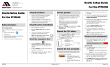
Connecting to your application
Connect the DVR-1000 to your vacuum manifold or application using
the 4' length of 1/4" x 5/8" o.d. rubber vacuum tubing provided by
CANNON
®
. Secure the tubing to the Vacuum Manifold Inlet on the
front panel of the DVR (see photo, next page). Push the tubing firmly
into place over the barbed nipple fitting. Attach the other end of the tube
to your manifold/application, clamping the connection if necessary.
Check all vacuum connections to make sure they are secure.
The DVR rear panel
(PORT connection}

6
CC
CC
C
ANNONANNON
ANNONANNON
ANNON
®
Digital Vacuum Regulator Instruction & Operation Manual
Version 1.3 — May, 2009; CANNON
®
Instrument Company
2139 High Tech Road • State College, PA • 16803 • USA
DVR front panel vacuum connection
DVR-1500 connections
The DVR-1500, although it has its own internal vacuum pump, uses the
identical front panel connection (see photo). Connect the DVR-1500 to
your vacuum manifold or application using the 4' length of 1/4" x 5/8"
o.d. rubber vacuum tubing provided by CANNON
®
. Secure the tubing to
the Vacuum Manifold Inlet on the front panel of the DVR. Push the
tubing firmly into place over the barbed nipple fitting. Attach the other
end of the tube to your manifold/application, clamping the connection if
necessary. Check the vacuum connections to make sure they are secure.
NOTE
The PORT connection on the rear of the DRV-1500 (see photo,
previous page) is used as an exhaust port for the vacuum. On this
model, use the CANNON
®
-supplied muffler to seal the port. Screw the
muffler onto the PORT connection, tightening the muffler finger-tight.
Vacuum trap
The glass bottle vacuum trap at the front of the DVR is designed to
prevent liquids from being pulled into the system and damaging the
internal components. The trap will only “catch” about two ounces of
fluid; it is not suitable for use as a reservoir or waste receptacle. In the
event that a small amount of fluid does enter the vacuum system, imme-
diately power down the unit and empty the glass bottle. You may also
wish to clean the 10’ rubber tubing with appropriate solvent(s). Thor-
oughly dry the tubing before reconnecting it to the DVR.
CAUTION
Pulling liquid solvent past the vacuum trap may cause internal damage
to DVR components and create a safety hazard.

7
CC
CC
C
ANNONANNON
ANNONANNON
ANNON
®
Digital Vacuum Regulator Instruction & Operation Manual
Version 1.3 — May, 2009; CANNON
®
Instrument Company
2139 High Tech Road • State College, PA • 16803 • USA
Electrical connections
After vacuum tubing connections have been made successfully, use the
power cord provided with the DVR to supply electricity to the unit.
WARNING
When supplying power to this instrument, connect the protective ground
(earth) terminals of the instrument to the protective conductor of the
(supplied) line (MAINS) power cord. The main plug for the power cord
should only be inserted in a socket outlet (receptacle) provided with a
protective ground (earth) contact.
Do not use an extension cord (power
cable) without a protective conductor (grounding).
The ~MAINS symbol indicates instructions or connections for the AC
power supply. The AC Power input must match the electrical specifica-
tions listed on the label on the rear panel of the instrument. The supplied
AC Mains power cord must be attached to the connector labelled
~MAINS. This connection serves as a means of disconnect and should be
readily accessible.
The (O) symbol indicates the OFF position for the electrical switches for
your unit (AC Mains or accessories).
Connecting power cable
1. Make sure that the 3-position switch on the front panel is set to the
center STANDBY position.
2. Plug the power cord into the DVR rear panel IEC power inlet con-
nector.
3. Plug the other end of the cord into an appropriate electrical outlet.

8
CC
CC
C
ANNONANNON
ANNONANNON
ANNON
®
Digital Vacuum Regulator Instruction & Operation Manual
Version 1.3 — May, 2009; CANNON
®
Instrument Company
2139 High Tech Road • State College, PA • 16803 • USA
This page intentionally left blank.

9
CC
CC
C
ANNONANNON
ANNONANNON
ANNON
®
Digital Vacuum Regulator Instruction & Operation Manual
Version 1.3 — May, 2009; CANNON
®
Instrument Company
2139 High Tech Road • State College, PA • 16803 • USA
CHAPTER
4
DVR OPERATION
Default settings
The DVR is designed to display and regulate vacuum for viscometry
applications per ASTM D 2171 specifications. The DVR regulates
vacuum using set points preset at CANNON
®
for efficient regulation of
vacuum at 300 mm Hg below atmospheric pressure.
To adjust the control settings to regulate at other pressures, see
section on adjusting HI/LO Setpoints.
Accessories
The DVR may be used in conjunction with the CANNON
®
3VM and
4VM vacuum manifolds. The 3VM manifold (catalogue # 9726-V10) has
three valves and is intended for use with the CANNON
®
CT-500 Con-
stant Temperature Bath. The 4VM manifold (catalogue # 9726-V05) has
four valves and is intended for use with the CANNON
®
CT-1000 and
CT-2000 Constant Temperature Baths.
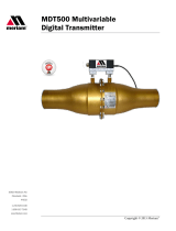
Turning on the DVR
Applying power
1. Make sure the instrument power cord is connected to an appropriate
power source (electrical requirements are specified on the rear panel
of the DVR unit).
2. Make sure that all vacuum connections are secure.
3. Toggle the POWER switch on the DVR front panel to the RUN
position (see photo). The gauge LCD will be activated and the
solenoid valves will “click” open. On DVR-1500 models, the internal
vacuum pump will engage.

10
CC
CC
C
ANNONANNON
ANNONANNON
ANNON
®
Digital Vacuum Regulator Instruction & Operation Manual
Version 1.3 — May, 2009; CANNON
®
Instrument Company
2139 High Tech Road • State College, PA • 16803 • USA
Meter Display/Key control options
Adjusting the flow rate
Solenoid regulators
Vacuum in the DVR system is regulated by two solenoid valves mounted
inside the DVR unit. The valves operate in tandem to maintain consistent
vacuum at the desired setting. Control set points for the solenoid valves are
preset at CANNON
®
to regulate vacuum at 300 mm Hg below atmo-
spheric pressure. If it is necessary to adjust these settings, see Chapter 5.
Rate Adjust knob
Solenoid valve efficiency is influenced by the rate of flow in the DVR
vacuum/pressure valve system. The flow rate is regulated with an internal
needle valve. This valve is adjusted manually from the DVR front panel
using the Rate Adjust knob.
Recovery/overshoot
The flow rate also affects the recovery time (the amount of time required
to restore desired vacuum settings when a significant change has oc-
curred) and the amount of overshoot (the degree of vacuum change in
excess of the desired reading observed before the vacuum stabilizes at the
desired setting).
Using the Rate Adjust knob
Set the Rate Adjust knob so that the instrument attains the desired
setting as quickly as possible without overshooting the control target by
more than 0.5 mm Hg. Turn the knob clockwise to decrease the flow rate
or counterclockwise to increase the flow rate.
Limiting overshoot
For example, if you are controlling at 300 mm Hg, increase the flow rate
until the overshoot produces a gauge reading greater than 300.5 mm Hg.
Than reduce the flow rate until the overshoot drops to less than 0.5 mm
Hg. You can check the new setting by opening and closing switches on
the vacuum manifold, causing a drop in vacuum. Then observe the
recovery time and overshoot.
CAUTION
It is impossible to totally close the needle valve controlled by the Rate
Adjust knob. Do not try to force the valve closed using to the Rate Adjust
knob, or you may damage the valve components.
NOTE For the needle valve to function efficiently, the solenoid SET 2 value
must be higher than the solenoid SET 1 value (see Chapter 5).
Bleeding vacuum
If the DVR instrument will not be used for a period of time, you may
toggle the front panel switch to the center STANDBY position. This
action disengages solenoid operation (both models) and turns off the
DVR-1500 vacuum pump.

11
CC
CC
C
ANNONANNON
ANNONANNON
ANNON
®
Digital Vacuum Regulator Instruction & Operation Manual
Version 1.3 — May, 2009; CANNON
®
Instrument Company
2139 High Tech Road • State College, PA • 16803 • USA
It is advisable to bleed off residual DVR system vacuum to 250 mm or
lower when the instrument is in the center STANDBY position. This will
prevent the unit from overshooting the target vacuum (default 300 mm
Hg) when the toggle switch is returned to the RUN position.
Adjusting OFFSET
“OFFSET”
The “OFFSET” command allows the user to adjust the reading relative to
a known value. To set the “OFFSET” use the following procedure:
1. Press and hold the SCAN/adj and HOLD/mode keys for 8 seconds,
then release; the display will alternate between “cal” and “noYes” for
ten seconds.
2. To specify “yes” and select “CH1”, press and hold the HOLD/mode
key to display “CH1” .
3. Press the HOLD/mode key to display “ALAr”.
4. Press the SCAN/adj key to display “OFFST”.
5. Press the HOLD/mode key to display the number “0”.
6. Set the value you wish the meter to display at the presently applied
pressure.
Press the SCAN/adj key to move the numbers up (+).
Press the HOLD/mode key to move the numbers down (-).
When the desired number is reached, press the SCAN/adj and
HOLD/mode keys at the same time. The number will flash
repeatedly. Then, press the SCAN/adj key to readjust the number
or the HOLD/mode key to accept it. After the number is ac-
cepted, the meter will display “bUSY” for 10 seconds and then
resume normal operation.
Adjusting HI/LO setpoints
NOTE The HI/LO alarm setpoints are used as control setpoints
“ALAr”
The “ALAr” command allows you to set high and low pressure alarm
points. The HI or LO indicator light is lit if the applied pressure exceeds
the set values. The alarm output signals are available at the terminal strip.
To set the Hi and Lo , use the following procedure:

12
CC
CC
C
ANNONANNON
ANNONANNON
ANNON
®
Digital Vacuum Regulator Instruction & Operation Manual
Version 1.3 — May, 2009; CANNON
®
Instrument Company
2139 High Tech Road • State College, PA • 16803 • USA
1. Press and hold the SCAN/adj and HOLD/mode keys for 8 seconds,
then release; the display will alternate between “cal” and “noYes” for
ten seconds.
2. To specify “yes” and select “CH1”, press and hold the HOLD/mode
key to display “CH1”.
3. Press the HOLD/mode key to display “ALAr”.
4. Press the HOLD/mode key to display the present value of the Low
Alarm point.
5. Set the LO ALARM Point.
NOTE
The decimal point that was set during calibration (CAL_U, CAL_C) will
be displayed.
Press the SCAN/adj key to move the numbers up (+).
Press the HOLD/mode key to move the numbers down (-).
When the desired number is reached, press the SCAN/adj and
HOLD/mode keys at the same time. The number will flash
repeatedly. Then, press the SCAN/adj key to readjust it or the
HOLD/mode key to accept it.
6. Repeat the same procedure as in Step 5 to set the HI ALARM Point.
After the number is accepted the DATUM 2000™ will resume normal
operation.
Selecting set point values
Control set points for the DVR have been determined empirically.
Selecting new set points to control at a different level of vacuum or at a
different unit of measurement, will involve some trial and error.
Once your control point (desired vacuum setting) is known, you must
select and test new set points. Normal factory set points may provide a
useful reference. The unit is shipped from CANNON
®
with a value of
292.5 mm Hg for LO and a value of 299.6 mm Hg for HI These settings
allow the DVR to control at 300 mm Hg ± the tolerance factor of 0.5 mm
Hg.
Mechanically, the DVR is plumbed so that the solenoid controlled by the Lo
register allows air to bypass the Rate Adjust valve. This feature makes it
possible to achieve a vacuum very close to the desired value in a very short
time. For the HI solenoid, the vacuum source is routed through the Rate
Adjust valve, permitting a finer adjustment. For accurate control, both set
points and the Rate Adjust valve must be set properly.
Remember that the Rate Adjust valve setting will vary depending on the
values chosen for the solenoid set points. When resetting the control
points you must also check/adjust the Rate Adjust knob.
Setting procedure

13
CC
CC
C
ANNONANNON
ANNONANNON
ANNON
®
Digital Vacuum Regulator Instruction & Operation Manual
Version 1.3 — May, 2009; CANNON
®
Instrument Company
2139 High Tech Road • State College, PA • 16803 • USA
CHAPTER
5
DVR CLEANING AND
MAINTENANCE
Cleaning
CAUTION
Before cleaning the DVR, turn off the instrument and unplug the power
cord. Do not clean the instrument while it is in operation.
Periodically clean the outside of the unit with a cloth moistened with
water and/or a mild detergent solution. Do not permit water or detergent
solution to drip into the unit electrical drawer. Wipe down the front panel,
sides and top. Remove the vacuum trap jar and wipe out the vacuum trap
enclosure and the glass jar. If there is oil or residue in the glass jar, use
the appropriate solvent and drying agent to clean the jar. Reattach the jar
after cleaning. The unit will be inoperable unless the vacuum trap is in
place.
Maintenance
Do not allow oil to accumulate in the vacuum trap. Remove the jar,
empty and clean as often as necessary. Make sure to remove power
from the instrument BEFORE removing the vacuum trap.
Periodically inspect the line cord for fraying and/or exposed wiring.
When removing the cord from the power outlet, pull it out by the
plug. Do not pull on the cord.
Troubleshooting the DVR
When you initially encounter a problem with the DVR, make sure that all
tubing and electrical connections are correct and secure, and that the
power switch is in the correct position.
Vacuum system leak
If the vacuum system is leaking, check the vacuum trap jar and make
certain that it is screwed tightly into position with the lip of the jar
contacting the cork seal on all sides.

DVR Manual – Chapter 5
Chapter 5 of DVR-1500 Manual: Altering
Factory Settings
The Meriam gauge installed on your DVR unit offers several programmable registers for adjusting the
operating parameters of the instrument. For a full description of programming options, consult the
Meriam manual included with your DVR instrument.
Changing the engineering unit of measurement
One of nine different units of measurement may be selected for the LCD.
Table 1: Engineering Units
Display
Unit of Measure
mm Hg
Millimeters of mercury
In ℎ
2
0
Inches ℎ
2
0
psi
Pounds per square inch
Kg/cm
2
Kilograms per square centimeter
kPa
Kilopascals
mbar
Millibars
bar
Bars
cmℎ
2
0
Centimeters ℎ
2
0
In Hg
Inches of mercury
None*
User units
*when user units are selected no engineering unit is displayed. See section Setting User Units for
instructions on defining User Units.
Changing engineering units (lockout not enabled)
1. To change engineering units when front panel lockout is not enabled (no password necessary)
press the UP (ENG UNITS) key when the gauge is in Measurement mode. The current
engineering unit will begin flashing.
2. Press the UP/DOWN arrow keys until the desired engineering unit is flashing.
3. Press the PRGM key. The gauge will return to Measurement mode with the new unit of
measure. The set point measurement values in the P registers will automatically be reset to
display and function using the selected engineering units.
Adjusting Control Set Points
To adjust the control set points you will set the P5 register to correspond to your desired set point
selection. Then you will change the numeric values for each set point. The decimal point location for
each set point will be determined after you have set the numeric value.

DVR Manual – Chapter 5
Note: During any programming operation, if there is no keypad activity for approximately one minute
the current programming operation will be aborted and the gauge will return to the Measurement
mode.
Adjustment Procedure: to adjust the control set points (SET 1 and SET 2)
1. Make certain the gauge is in the measurement mode displaying the current vacuum/pressure
reading.
2. Turn the DVR front panel switch to the METER setting.
3. Press the PRGM key. The gauge will display the P0 register indicator.
Note: if lockout is enabled, you will be prompted to enter the lockout code. See Front Panel Lockout.
4. Use the UP/DOWN arrow keys to scroll though the register options until you get to the P5
register.
5. When the gauge LCD displays P5, press the PRGM key again to display the current register
setting.
6. Use the UP/DOWN arrow keys to scroll through the P5 program options until the desired
setting (3, if both set points are desired) is displayed. See below. Then press the PRGM key.
a. Select 0 to disable control for both set points
b. Select 1 to enable Set Point 1 only (P6 register)
c. Select 2 to enable Set Point 2 only (P7 register)
d. Select 3 to enable Set Points 1 & 2 (P6 & P7 registers)
7. Use the UP/DOWN arrow keys to scroll through the register options until the P6 register is
displayed.
8. Press the PRGM key to display the current setting for the set point. Notice that the left-most
digit is flashing.
9. Use the UP/DOWN arrow keys to change the digit to the desired value. Then press PRGM
again. The next numeral will begin flashing.
10. Repeat step 9 until all numeric values have been reset and the decimal point is flashing.
11. Press the UP/DOWN keys to relocate the decimal point until the desired value for the set point
is displayed on the LCD.
12. Press PRGM to save the new value to the register. The LCD will display the P register.
13. Press the UP key to display the P7 register.
14. Repeat steps 8 through 12 to adjust the P7 set point value.
15. When both set points have been set correctly press the ON/OFF key to return to the
measurement mode.
Selecting Set Point Values
Control set points for the DVR have been determined empirically. Selecting new set points to control at
a different level of vacuum or at a different unit of measurement will involve some trial and error.

DVR Manual – Chapter 5
Once your control point (desired vacuum setting) is known, you must select and test new set points.
Normal factory set points may provide a useful reference. The unit is shipped from CANNON® with a
value of 292.5 mm Hg for SET1 and a value of 299.6 mm Hg for SET2. These settings allow the DVR to
control at 300 mm Hg ± the tolerance factor of 0.5 mm Hg.
Mechanically, the DVR is plumbed so that that solenoid controlled by the SET1 register allows air to
bypass the Rate Adjust valve. This feature makes it possible to achieve a vacuum very close to the
desired value in a very short time. For the SET2 solenoid, the vacuum source is routed through the Rate
Adjust valve, permitting a finer adjustment. For accurate control, both set points and the Rate Adjust
valve must be set properly.
Remember that the Rate Adjust valve setting will vary depending on the values chosen for the solenoid
set points. When resetting the control points you must also check/adjust the Rate Adjust knob.
/