Vallox 99 MV CF User manual
- Category
- Split-system air conditioners
- Type
- User manual
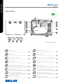
Vallox 99 MV CF is a versatile ventilation unit designed to provide a comfortable and healthy indoor climate in your home. With its energy-efficient operation and a variety of features, it offers customized ventilation solutions for your specific needs.
Vallox 99 MV CF is a versatile ventilation unit designed to provide a comfortable and healthy indoor climate in your home. With its energy-efficient operation and a variety of features, it offers customized ventilation solutions for your specific needs.


-
 1
1
-
 2
2
-
 3
3
-
 4
4
-
 5
5
-
 6
6
-
 7
7
-
 8
8
-
 9
9
-
 10
10
-
 11
11
-
 12
12
-
 13
13
-
 14
14
-
 15
15
-
 16
16
-
 17
17
-
 18
18
-
 19
19
-
 20
20
-
 21
21
-
 22
22
-
 23
23
-
 24
24


Vallox 99 MV CF User manual
- Category
- Split-system air conditioners
- Type
- User manual
Vallox 99 MV CF is a versatile ventilation unit designed to provide a comfortable and healthy indoor climate in your home. With its energy-efficient operation and a variety of features, it offers customized ventilation solutions for your specific needs.
Ask a question and I''ll find the answer in the document
Finding information in a document is now easier with AI
Related papers
-
Vallox 125 MV User manual
-
-
Vallox 096 MV User manual
-
Vallox MyVallox Touch Control Panels User manual
-
-
-
-
-
Vallox MyVallox User manual
-
Other documents
-
Airflow DV96 (R) Adroit Operating instructions
-
HQ W8-65050N Datasheet
-
-
FläktGroup ILOX 129PLUS Installation and Maintenance Manual
-
-
Komfovent DOMEKT C6M Installation guide
-
-
Swegon CASA R5 Smart Owner's manual
-
-