EDS-75-S
EDS-100-S/F
EDS-160-S/F
EDS-200-S/F
EDS-220-Z
EDS-250-S/F
EDS-260-Z
EDS-300-S/F/Z
EDS-370-Z
EDS-400-S/F/Z
EDS-500-S
EDS-630-S/F
Instruction Manual
induSENSOR, EDS

Long-Stroke sensors, Series EDS
MICRO-EPSILON
MESSTECHNIK
GmbH & Co. KG
Königbacher Straße 15
94496 Ortenburg / Germany
Tel. +49 (0) 8542 / 168-0
Fax +49 (0) 8542 / 168-90
e-mail [email protected]
www.micro-epsilon.com
Certified acc. to DIN EN ISO 9001: 2008

induSENSOR, EDS
Contents
1. Safety ........................................................................................................................................ 5
1.1 Symbols Used ................................................................................................................................................. 5
1.2 Warnings .......................................................................................................................................................... 5
1.3 Notes on CE Identification ............................................................................................................................... 6
1.4 Proper Use ....................................................................................................................................................... 6
1.5 Proper Environment ......................................................................................................................................... 7
2. Functional Principle, Technical Data ....................................................................................... 8
2.1 Measuring Principle ......................................................................................................................................... 8
2.2 Structure .......................................................................................................................................................... 9
2.3 Technical Data ............................................................................................................................................... 10
3. Delivery ................................................................................................................................... 12
3.1 Unpacking ...................................................................................................................................................... 12
3.2 Storage .......................................................................................................................................................... 12
4. Installation and Assembly ...................................................................................................... 13
4.1 Precautionary Measures ................................................................................................................................ 13
4.2 Measuring Tube Guide and Fastening .......................................................................................................... 13
4.3 Sensor Mounting ........................................................................................................................................... 15
4.3.1 Model EDS- ... -S .......................................................................................................................... 15
4.3.2 Model EDS- ... -F .......................................................................................................................... 22
4.3.3 Model EDS- ... -Z .......................................................................................................................... 24
4.4 Power Supply and Display/Output Device .................................................................................................... 27
4.4.1 Model EDS- ... -S .......................................................................................................................... 27
4.4.2 Model EDS- ... -F .......................................................................................................................... 29
4.4.3 Model EDS-...-Z ............................................................................................................................ 30
4.4.4 Load Resistor, Maximum Operating Temperature ....................................................................... 32

induSENSOR, EDS
5. Operation ................................................................................................................................ 33
6. Operation and Maintenance .................................................................................................. 33
7. Warranty .................................................................................................................................. 34
8. Decommissioning, Disposal .................................................................................................. 34
9. Appendix ................................................................................................................................. 35

Page 5
induSENSOR, EDS
1. Safety
The handling of the system assumes knowledge of the instruction manual.
1.1 Symbols Used
The following symbols are used in this instruction manual:
Indicates a hazardous situation which, if not avoided, may result in minor or moder-
ate injury.
Indicates a situation which, if not avoided, may lead to property damage.
Indicates a user action.
i
Indicates a user tip.
1.2 Warnings
Connect the power supply according to the safety regulations for electrical operating equipment.
> Danger of injury
> Damage to or destruction of the sensor
The supply voltage must not exceed specified
limits.
> Damage to or destruction of the sensor
Avoid banging and knocking the sensor.
> Damage to or destruction of the sensor
Avoid bending the sensor rod or the alu tube.
> Damage to or destruction of the sensor
Do not transport the sensor on the sensor rod.
> Damage to or destruction of the sensor
Sensor-
housing
Alu tube
Sensor rod
Sensor
housing

Page 6
induSENSOR, EDS
1.3 Notes on CE Identification
The following applies to EDS eddy current long stroke displacement sensors:
- EU directive 2004/108/EC
- EU directive 2011/65/EC, “RoHS” category 9
Products which carry the CE mark satisfy the requirements of the quoted EU directives and the European
standards (EN) listed therein. The EC declaration of conformity is kept available according to EC regulation,
article 10 by the authorities responsible at
MICRO-EPSILON MESSTECHNIK
GmbH & Co. KG
Königbacher Straße 15
94496 Ortenburg / Germany
The measuring system is designed for use in industry and satisfies the requirements.
1.4 Proper Use
- The sensors are used for
displacement measurement in presses, punches, rolling mills, ect
position determination of piston in hydraulic and pneumatic cylinders
- The sensors may only be operated within the limits specified in the technical data, see Chap. 2.3.
- Use it in such a way that with malfunctions or total failure of the sensor, persons are not endangered and
machines are not damaged.
- Take additional precautions for safety and damage prevention for safety-related applications.

Page 7
induSENSOR, EDS
1.5 Proper Environment
- Protection class for sensor
Sensor rod IP 69K
Electronics: IP 67
1
- Operating temperature: -40 °C up to +85 °C (-40 up to +185 °F), R
L
= 500 Ohm
- Storage temperature: -40 °C up to +100 °C (-40 up to +212 °F)
- Humidity: 5 - 95 % (non-condensing)
- Ambient pressure: 450*10
5
Pa (1 Pa = 1 N/m
2
) max.
2
1) Models with male plug connection only with gasketed female plug
2)
Confined on sensor rod

Page 8
induSENSOR, EDS
2. Functional Principle, Technical Data
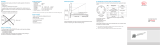
2.1 Measuring Principle
The eddy current long stroke displacement sensors transform a linear motion (for example piston position in
hydraulic cylinders) into a linear, electrical signal. An aluminium tube, moving concentrically around a sensor
rod, is used as target. Energy is transferred from the coil by inducing of eddy currents in the aluminium tube
and it is detuned as a result. The integrated, miniaturized electronics convert the tube position into a linear,
electrical output signal. The eddy current measuring principle works without contact between moving parts
and is therefore free of wear.
0 1/1
4
12
20
Sensor
housing
Sensor rod
Output signal (mA)
Measuring range
1/2
Alu tube
Fig. 1 Measuring Principle of an eddy current long stroke displacement sensor, alu tube at the start of the
measuring range

Page 9
induSENSOR, EDS
2.2 Structure
A coil is mounted inside the sealed rod, protected against environmental influences. The micro-electronics is
integrated in the sensor housing. A pressure-proof, stainless steel housing is available as an option. The sen-
sors are used for measuring lengths from 100 to 630 mm.
Electrical connection:
- Connector 4-pins, type Amphenol C164P compact (Model EDS-...-S...)
1
- Connector 7-pins, type Binder 712 (Model EDS-...- S ...7...)
- Connector 5-pins, CA02COM-E14S with bayonet connection (Model EDS-...-F...)
- Wire, axial (model EDS-...-Z...)
1) Previous model no longer available

Page 10
induSENSOR, EDS
2.3 Technical Data
Model
EDS
-75
EDS
-100
EDS
-160
EDS
-200
EDS
-220
EDS
-250
EDS
-260
EDS
-300
EDS
-370
EDS
-400
EDS
-500
EDS
-630
Connections S S, F S, F S, F Z S, F Z S, F, Z Z S, F, Z S S, F
Measuring range mm 75 100 160 200 220 250 260 300 370 400 500 630
Linearity ±0.3 % FSO mm 0.23 0.3 0.48 0.6 0.66 0.75 0.78 0.9 1.1 1.2 1.5 1.89
Resolution 0.05 % FSO mm 0.038 0.05 0.08 0.1 0.11 0.125 0.13 0,15 0.18 0.2 0.25 0.315
Repeatability 0.05 % FSO
Temperature range -40 °C ... +85 °C
Temperature stability ±200 ppm / °C
Frequency response -3 dB 150 Hz, optional up to 300 Hz
Output signal 4 - 20 mA
Output load ≤500Ohm
Power supply 18 - 30 VDC
Current consumption max. 40 mA
Connector
Model S 7-pin connector (sensor cable as an option), options radial or axial output
Model F 5-pin radial bayonet-connector with mating plug
Model Z Wire axial
Pressure resistance 450*10
5
Pa max. (Sensor rod, flange)
1
Protection class Sensor rod: IP 69K, elektronics: IP 67
2
Shock
3
IEC 68-2-29
IEC 68-2-27
40 g, 3000 shocks per axis
100 g radial, 300 g axial
Vibration EC 68-2-6
5 Hz ... 44 Hz ±2.5 mm
44 Hz ... 500 Hz ±23 g

Page 11
induSENSOR, EDS
Model
EDS
-75
EDS
-100
EDS
-160
EDS
-200
EDS
-220
EDS
-250
EDS
-260
EDS
-300
EDS
-370
EDS
-400
EDS
-500
EDS
-630
Connections S S, F S, F S, F Z S, F Z S, F, Z Z S, F, Z S S, F
Sensor material V4A-Steel 1.4571
Tube material AlMgSi, enodized
Sensor weight
EDS-...-S
g
150 170 160 220 --- 250 --- 280 --- 470 560 650
EDS-...-F --- 1260 1270 1300 --- 1320 --- 1350 --- 1560 --- 1750
EDS-...-Z --- --- --- --- 340 --- 370 370 570 570 --- ---
Alu tube
S 20 30 40 40 --- 50 --- 60 --- 90 115 140
F --- 40 40 40 --- 50 --- 60 --- 140 --- 210
Z --- ---- --- --- 46 --- 54 60 92 90 --- ---
FSO = Full Scale Output
1) For all models confined on sensor rod
2) With gasketed female plug.
3) Half sinusoid 6 ms.

Page 12
induSENSOR, EDS
3. Delivery
3.1 Unpacking
Do not take and hold the sensor at the sensor rod.
Check for completeness and shipping damage immediately after unpacking.
The delivery of an eddy current long stroke displacement sensor includes:
1 Eddy current long stroke displacement sensor 1 O-ring (mounted on sensor)
1
1 Measuring tube 1 Test report
1 Instruction manual
In case of damage or missing parts, please contact the manufacturer or supplier.
3.2 Storage
- Storage temperature: -40 °C up to +100 °C (-40 up to +212 °F)
- Humidity: 5 - 95 % (non-condensing)
- Atmospheric pressure
1) For sensor models S and F only
Sensor
housing

Page 13
induSENSOR, EDS
4. Installation and Assembly
4.1 Precautionary Measures
The measuring tube must not contact the sensor rod during operation.
> Damage to or destruction of the sensor through abrasion is possible.
Do not deform or shorten the measuring tube.
> Loss of specified technical data.
Do not crush the O-ring or damage through sharp-edged items.
> Loss of functionality
4.2 Measuring Tube Guide and Fastening
Mount the measuring tube in the piston bore hold.
The dimensions for the measuring tube are shown, see Fig. 8 et seq. When the piston is moved in the measu-
ring tube must not touch the sensor shaft. Observe the measuring tube position at the zero point
(= 4 mA output), see Fig. 2 et seq. A slightly eccentric mounting of the measuring tube has no negative influ-
ence on the sensor signal.
Mount the measuring tube in the piston by means of pressing or glueing.
Spot clamping is not permissible.
i
The specified technical data are valid only if the measuring tube is used supplied by
MICRO-EPSILON!

Page 14
induSENSOR, EDS
a
a
Fig. 2 Zero point of the measuring tube, EDS- ... -S Fig. 3 Zero point of the measuring tube, EDS- ... -F
a
Measuring range Dimension a
75 15 (0.59)
100 20 (0.79)
160 20 (0.79)
200 20 (0.79)
220 20 (0.79)
250 20 (0.79)
260 20 (0.79)
Fig. 4 Zero point of the measuring tube, EDS- ... -Z 300 20 (0.79)
370 25 (0.98)
Dimensions in mm, not to scale 400 25 (0.98)
500 25 (0.98)
630 25 (0.98)

Page 15
induSENSOR, EDS
4.3 Sensor Mounting
4.3.1 Model EDS- ... -S
Mount the sensor in the cylinder with a mounting ring (Appendix), see Fig. 12 and six cylinder head bolts
(M5x10).
Sealing is effected at the sensor shaft by means of an O-ring supplied.
Displacement
sensor
O-ring
Piston
Sensor shaft
CylinderSensor rod
21HB
Mounting ringM5x10 Alu tube
Fig. 5 Sensor mounting in a hydraulic cylinder, model EDS- ... -S
Sealing
O-Ring: 18.5x1.5
Material: Viton
Dimension Fit tolerance
µm
21H8
+33
0
Diameter of the borehole: 21H8 dia.
Borehole surface:
R
a
= 0.8
R
max
= 3.2

Page 16
induSENSOR, EDS
Bushing for
connector
15
(.6)
ø34 (1.4 dia.)
ø31
(1.2 dia.)
40 (1.6)
Use a connection piece for moun-
ting, see Fig. 6. The bushing must
be congruent with the connector for
models with radial connector.
Fig. 6 Mounting of an induSENSOR, model EDS- ... -S
Groove
Use an extractor for dismounting,
see Fig. 7.
Dimensions of the flange groove:
1.5 x 1.5 mm
(.06 x .06 “,depth x width).
Fig. 7 Dismounting of an induSENSOR, model EDS- ... -S
Dimensions in mm, not to scale

Page 17
induSENSOR, EDS
Dimensional drawing, model EDS- ... -S
32.5 (1.28)
4
+0.1
(.16
+0.1
)
8
-0.1
(.32
-0.004
)
ø34
-0.1
(1.34
-0.004
dia.)
ø21f7 (.83 dia.)
ø10 (.39 dia.)
1.5 (.06)
Sensor rod L
Alu tube I
ø30 (1.18 dia.)
l
L
d
min 30
(1.18)
A
B
Fig. 8 induSENSOR with axial connector, model EDS- ... -SA7 - I,
measuring range: 75 (2.95) / 100 (3.94) / 160 (6.29) / 200 (7.87) /
250 ( 9.84) / 300 (11.81)
Dimension Fit tolerance
µm
A B
21f7
-20
-41
EDS-xxx-S-Sx-l
1
31 (1.2) 16 (.63)
EDS-xxx-S-Sx7-l 51 (2.0) 47 (1.85)
Dimensions in mm (inches), not to scale
1)
Previous model no longer available.
Measuring
range
Sensor rod L Alu tube I Alu tube d
100
(3.93)
140
(5.51)
140
(5.51)
16
(.63)
160
( 6.29)
200
(7.87)
200
(7.87)
16
(.63)
200
(7.87)
240
(9.45)
240
(9.45)
16
(.63)
250
(9.84)
290
(11.42)
290
(11.42)
16
(.63)
300
(11.81)
340
(13.39)
340
(13.39)
16
(.63)

Page 18
induSENSOR, EDS
13
(0.51)
A
Fig. 9 induSENSOR with radial connector, model EDS- ... -SR7 - I, measuring range: 75 (2.95) / 100 (3.94) /
160 (6.29) / 200 (7.87) / 250 (9.84) / 300 (11.81)
A
EDS-xxx-S-Sx-I
1
31
(1.2)
EDS-xxx-S-Sx7-I
51
(2.0)
Dimensions in mm, not to scale
1) Previous version no longer available.

Page 19
induSENSOR, EDS
32.5 (1.28)
4
+0.1
(.16
+0.1
)
1.5 (.06)
Sensor rod L
Alu tube I
ø30 (1.18 dia.)
ø12(.47 dia.)
d
16
-0,1
(.63
-0.004
)
l
L
ø21f7
(.83 dia.)
min 30
(1.18)
A
B
ø34
-0.1
(1.34
-0.004
dia.)
Fig. 10 induSENSOR with axial connector, model EDS- ... -SA7 - I, measuring range: 400 (15.74) / 500 (19.69) /
630 (24.80), dimensions in mm (inches), not to scale
Dimension Tolerance
µm
A B
21f7
-20
-41
EDS-xxx-S-Sx-l
1
31
(2.19)
16
(.63)
EDS-xxx-S-Sx7-l
51
(2.1)
47
(1.85)
Measuring
range
Sensor rod Alu tube
L I d
400 (15.74) 450 (17.72) 450 (17.72) 18 (.71)
500 (19.69) 550 (21.65) 550 (21.65) 18 (.71)
630 (24.80) 680 (26.77) 680 (26.77) 18 (.71)
1) Previous version no longer
available.

Page 20
induSENSOR, EDS
13
(0.51)
A
Fig. 11 induSENSOR with radial connector, model EDS- ... -SR7 - I, measuring range: 400 (15.74) / 500 (19.69)
/ 630 (24.80)
A
EDS-xxx-S-Sx-I
1
31 (1.2)
EDS-xxx-S-Sx7-I 51 (2.0)
Dimensions in mm (inches), not to scale
1) Previous version no longer available.
Page is loading ...
Page is loading ...
Page is loading ...
Page is loading ...
Page is loading ...
Page is loading ...
Page is loading ...
Page is loading ...
Page is loading ...
Page is loading ...
Page is loading ...
Page is loading ...
Page is loading ...
Page is loading ...
Page is loading ...
Page is loading ...
/