Page is loading ...

Page 9
English
induSENSOR, EDS, model Z
1. Warnings
Connect the power supply according to the safety regulations for electrical operating equipment.
> Danger of injury, damage to or destruction of
the sensor
The supply voltage must not exceed specified
limits. Avoid banging and knocking the sensor. Avoid bending
the sensor rod or the alu tube. Do not transport the sensor on the
sensor rod.
> Damage to or destruction of the sensor
2. Notes on CE Identification
The following applies to EDS eddy current long stroke displacement sensors: EMC regulation 2004/108/EC
The eddy current long stroke displacement sensors satisfy the requirements of the standards
DIN EN 61326-1: 2006-10 and DIN 61326-2-3: 2007-05
The sensors satisfy the requirements if they comply with the regulations described in the instruction manual
for installation and operation.
3. Proper Invironment
- Protection class for sensor:
Sensor rod: IP 69K
Elektronics: IP 67
1
- Operating temperature:
-40 °C to +85 °C (-40 to 185 °F),
R
L
= 500 Ohm
- Storage temperature:
-40 °C to +100 °C
(-40 to +212 °F)
- Humidity:
5 - 95 %
(no condensation)
- Ambient pressure:
450*10
5
Pa (1 Pa = 1 N/m
2
) max.
2
- EMC according to:
DIN EN 61326-1: 2006-10
DIN 61326-2-3: 2007-05
1) Models with male plug connection only with gasketed female plug
2) Confined on sensor rod
Sensor housing
Sensor rod
Alu tube

Page 10
induSENSOR, EDS, model Z
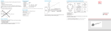
4. Measuring Principle
0
1/1
4
12
20
Output signal (mA)
Measuring range
1/2
Sensor rod
Alu tube
Fig. 1 Measuring Principle of an eddy current long stroke dis-
placement sensor, alu tube is shown at the start of the measu-
ring range
5. Unpacking, Shipping
Do not take and hold the sensor
at the sensor rod.
Check for completeness and ship-
ping damage immediately after
unpacking.
6. Installation and Assembly
6.1 Measuring Tube Guide and Fastening
Mount the measuring tube in the piston borehold.
The dimensions for the measuring tube, see Fig. 4. When the piston
is moved in the measuring tube must not touch the sensor shaft.
Observe the measuring tube position at the zero point (= 4 mA out-
put), see Fig. 2. A slightly eccentric mounting of the measuring tube
has no negative influence on the sensor signal.
Mount the measuring tube in the piston by means of pressing
or glueing.
Spot clamping is not permissable.
i
The specified technical data are valid only if the
measuring tube is used supplied by MICRO-EPSILON!
a
Fig. 2 Zero point of the measuring tube
Measuring range 220 260 300 370 400
Dimension a
20
(0.79)
20
(0.79
20
(0.79)
25
(0.98
25
(0.98)

Page 11
English
induSENSOR, EDS, model Z
6.2 Sensor Mounting
The sensor is fixed in the cylinder with a grub screw and clamped from the back panel. Sealing is effected at the sensor shaft by me-
ans of an O-ring.
Feed the connecting wires in able duct outwards and connect them with the mounting plug.
Grub screw
Sensor rod Alu tube PistonBack panel
O- ring
Adapter
M12x1 Mounting plug, 4-pin.
48H8
>
25
>18
15
Fig. 3 Sensor mounting in a hydraulic cylinder
Sealing
(not included in the delivery)
Diameter of the borehole: 48H8 dia.
O-Ring: 44.12x2.62 Borhole surface:
Material: Viton R
a
= 0.8
R
max
= 3.2
Alu tube must be
flush with the piston
Dimension Tolerance
µm
48H8
+39
0

Page 12
induSENSOR, EDS, model Z
6.3 Dimensional Drawing
Alu tube I
Sensor rod L
33 (1.3)
21(0.82)
12
(0.47)
1 x 45 °
M24x1.5
ø44
-0.1
(1.73
-0.004
dia.)
ø44
-0.3
(1.73
-0.12
dia.)
ø48f7 (1.89 dia.)
d
D
Fig. 4 induSENSOR
with axial wires, model
EDS- ... -Z, dimensions
in mm (inches), not to
scale
Dimension Tolerance
µm
48f7
-25
-50
Measuring
range
Sensor rod Alu tube
L D I d
220 (8.66) 252 (9.92) 10 (.39) 250 (9.84) 16 (.63)
260 (10.23) 292 (11.50) 10 (.39) 290 (11.42) 16 (.63)
300 (11.81) 341 (13.43) 10 (.39) 340 (13.39) 16 (.63)
370 (14.57) 457 (18.00) 12 (.47) 450 (17.72) 18 (.71)
400 (15.74) 457 (18.00) 12 (.47) 450 (17.72) 18 (.71)

Page 13
English
induSENSOR, EDS, model Z
Use an extractor pipe for dismounting, see Fig. 5.
Female thread in the extractor pipe: M24 x 1.5
Proceeding:
1. Unplug the adapter.
2. Release the grub screw.
3. Screw on the extractor pipe on the sensor shaft and pull out the sensor from the cylinder.
Extractor pipe
1
2
3
Fig. 5 Dismounting of the induSENSOR, model EDS-...-Z

Page 14
induSENSOR, EDS, model Z
6.4 Power Supply and Display/Output Device
Power supply and signal output are effected through the 4-contact connector on the hydraulic cylinder. The pin assignment, see Fig. 6.
Pin Assignment Color A 4-pin cable socket for the user-side assembly of your
own connecting cable is part of the delivery scope.
Fig. 6 Table Connection pin assignment, view of solder pin
side female cable connector
1 Signal ground brown
2 Power supply + (18 ... 30 VDC) white
3 Signal (4 ... 20 mA) blue
4 Supply ground black
EDS-...-Z EDS-...-Z
Fig. 7 Signal monitoring with amperemeter
R
L
can be inserted as an option for adaptation of the power
loss to high ambient temperatures.
Fig. 8 Signal monitoring with load resistor and voltmeter
If the signal is monitored with a voltmeter the load resistor
R
L
is dimensioned in accordance with the desired output
voltage U
OUT
.
Formula:
U
OUT
= R
L
* I
Signal

Page 15
English
induSENSOR, EDS, model Z
The sensors are connected according to the pin assignment shown, see Fig. 6
et seq. Notice the different criterias:
- R
L max
= (U
B
- 10 V) / 20 mA
- R
L min
= 82.5 * 1/V * U
B
- 1625 Ohm
- T
max
= 150 °C - 3.3 °C/V * U
B
+ 0.04 °C/W * R
L
The maximum load resistor R
L
is limited by the operating voltage U
B
.
20 mA
- 10 V)(U
B
=
R
L max
A small load resistor loads the sensor electronics more thermical. With a ma-
ximum operating temperature of 85 °C (+185 °F) the minimum load resistor R
L
permitted is calculated as:
R = - 1625 Ohm
L min
82.5 * U
V
B
(If the result is negative: R
L
= 0 Ω)
With a preset load resistor the maximum operating temperature permitted is
calculated as:
T = 150 °C - +
0.04 * R
L
max
3.3 * U
V
B
Ohm
;
and T
max
≤ 85 °C
R
L
= Load resistor
U
B
= Operating voltage
T
max
= Maximum operating temperature

X977X051.03-A021123HDR
*X977X051.03-A02*
MICRO-EPSILON MESSTECHNIK GmbH & Co. KG
Königbacher Str. 15 · 94496 Ortenburg / Germany
Tel. +49 (0) 8542 / 168-0 · Fax +49 (0) 8542 / 168-90
[email protected] · www.micro-epsilon.com
/