Page 2
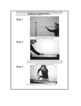
Installing RadianceRail
®
with Balusters
Measuring Your Railing Area
Important Information
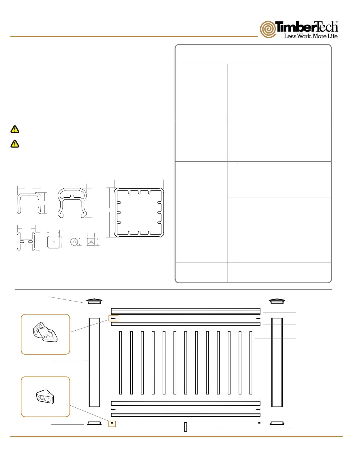
Component Dimensions
Tools Required
Components Needed For Installing
One RadianceRail
®
Section
RadianceRail
®
is available in 10’, 8’, and 6’ lengths.
• Measurements are from center to center of the posts. Rails
are produced in 10’, 8’, and 6’ lengths to allow for finished
end cuts and angles.
• Determine how many 10’, 8’, and 6’ RadianceRail sections
you need and check to be sure you have all the components
(and quantities) listed in the chart shown to the right.
• RadianceRail 10’, 8’, and 6’ Rails are designed not to exceed
10’, 8’, and 6’’ center of post to center of post, respectively.
• For stair applications maximum rail length must not exceed 91”
• Cut slowly, using a fine tooth saw blade to avoid chipping.
• For 42” railing use 12’ Post Sleeves.
• Custom Rail Packs should be used when installing Aluminum
Balusters.
• Miter Saw
• Drill
• Measuring Tape
• 7/64” Drill Bit
• 3/16” Drill Bit
Components Included
in Complete 6’ and 8’
Kits (white only).
Visit www.timbertech.com/installation to view TimberTech installation videos.
Consult your local building codes for guard and handrail requirements.
Components available
separately for
mix-and-match rail
systems
Additional Components
Needed for Each
System
1 - Top Rail
1 - Bottom Rail
2 - Support Rails
Foot Blocks
- 1 in 6’ kits
- 2 in 8’ Kits
Square Balusters
-13 in 6’ Kits
-18 in 8’ Kits
Hardware Mounting Kit
Support Block Mounting Templates
Baluster Screw Kit
1 - Top Rail
1 - Bottom Rail
2 - Support Rails (1 - Aluminum Top Support Rail for 10')
Hardware Mounting Kit
Support Block Mounting Templates
Foot Blocks
- 1 in 6’ Packs, - 2 in 8’ Packs, - 3 in 10’ Packs
RadianceRail Pack
Baluster Pack
Hardware Mounting Kit
4 - Mounting Brackets
2 - Support Blocks
16 - #8 x 3/4” Screws
6 - #8 x 1 3/4” Screws
6 - #8 x 2 5/8” Screws (Stairs Only)
3 - #8 x 3” Screws
12 - #8 x 3” Green Screws
T20 Driver Bit
2 - Post Caps
2 - Post Sleeve
2 - Post Skirts
5”
5”
2.9”
3”2.25”
2.5”
1.8”
1.8”
1.25”
1.25”
.75”
Top Rail
Post Sleeve
Bottom Rail
Support Rail
Square
Composite
Baluster
Round
Aluminum
Baluster
Square
Aluminum
Baluster
Post Cap (2)
Top Rail (1)
Mounting Bracket (4)
Support Rail (2)
Support Block (2)
Bottom Rail
Post Sleeve (2)
Composite Baluster
(23 in 10’ Section)
(18 in 8’ Section)
(13 in 6’ Section)
Aluminum Baluster
(25 in 10’ Section)
(20 in 8’ Section)
(15 in 6’ Section)
Post Skirt (2)
Foot Block
(3 in 10’ Section)
(2 in 8’ Section)
(1 in 6’ Section)
.75”
.75”
.75”
Baluster Screw Kit
18 - #8x2” Screws
18 - #8x3” Screws
Baluster Screw Kit
20 - #8x2” Screws
20 - #8x3” Screws
Composite Balusters
- 18 Balusters per Pack
(23 required per 10’ section)
(18 required per 8’ section)
(13 required per 6’ section)
- 29” for 36” Railing
- 31” for 36” Railing
(with less than 2” gap
between deck & Bottom Rail)
- 35” for 42” Railing
- 37” for 42” Railing
(with less than 2” gap
between deck & Bottom Rail)
Aluminum Balusters
- 20 Balusters per Pack
(25 required per 10’ section)
(20 required per 8’ section)
(15 required per 6’ section)
- 29” for 36” Railing
- 31” for 36” Railing
(with less than 2” gap
between deck & Bottom Rail)
- 35” for 42” Railing
- 37” for 42” Railing
(with less than 2” gap
between deck & Bottom Rail)
Hardware included in
Hardware Mounting
Kits: