Page is loading ...

MICRO-EPSILON Eltrotec GmbH
Manfred-Wörner-Straße 101 · 73037 Göppingen / Germany
Tel. +49 (0) 7161/98872-300 · Fax +49 (0) 7161/98872-303
[email protected] · www.micro-epsilon.de
Your local contact: www.micro-epsilon.com/contact/worldwide/
ILR2250-100
Operating Instructions
optoNCDT ILR2250

Laser distance measuring device
Non-contact laser-optic distance sensor
MICRO-EPSILON Eltrotec GmbH
Manfred-Wörner-Straße 101
73037 Göppingen / Germany
Tel. +49 (0) 7161 / 98872-300
Fax +49 (0) 7161 / 98872-303
e-mail [email protected]
www.micro-epsilon.com

optoNCDT ILR2250
Contents
1. Safety ........................................................................................................................................ 5
1.1 Symbols Used ................................................................................................................................................. 5
1.2 Warnings .......................................................................................................................................................... 5
1.3 Notes on CE Marking ...................................................................................................................................... 6
1.4 Intended Use ................................................................................................................................................... 6
1.5 Proper Environment ......................................................................................................................................... 6
2. Laser Safety .............................................................................................................................. 7
3. Functional Principle, Technical Data ....................................................................................... 8
3.1 Short Description ............................................................................................................................................. 8
3.2 Measuring Principle ......................................................................................................................................... 8
3.3 Term Definitions, Analog Output Displacement .............................................................................................. 8
3.4 Technical Data ................................................................................................................................................. 9
4. Delivery ................................................................................................................................... 10
4.1 Unpacking/Included in Delivery .................................................................................................................... 10
4.2 Storage .......................................................................................................................................................... 10
5. Installation and Assembly ...................................................................................................... 11
5.1 Notes for Operation ....................................................................................................................................... 11
5.1.1 Reflectance of Target Surface ..................................................................................................... 11
5.1.2 Interferences ................................................................................................................................. 12
5.1.2.1 Ambient Light ............................................................................................................ 12
5.1.2.2 Thermal Influences ................................................................................................... 12
5.1.2.3 Mechanical Vibrations .............................................................................................. 12
5.1.2.4 Motion Blur ............................................................................................................... 12
5.1.2.5 Angular Influences ................................................................................................... 12
5.2 Mechanical Fastening .................................................................................................................................... 13
5.2.1 Sensor Installation ........................................................................................................................ 13
5.2.2 Start of Measuring Range............................................................................................................. 14
5.2.3 Reflector Installation ..................................................................................................................... 14
5.3 Display Elements ........................................................................................................................................... 14
5.4 Electrical Connections ................................................................................................................................... 15
5.4.1 Connection Options ..................................................................................................................... 15
5.4.2 Pin Assignment ............................................................................................................................. 16
5.4.3 Supply Voltage ............................................................................................................................ 16
5.4.4 Analog Output .............................................................................................................................. 17
5.4.5 RS422 (with IF2001/USB Converter) ............................................................................................ 18
5.4.6 Trigger Input ................................................................................................................................ 19
5.4.7 Switching Output ......................................................................................................................... 19
6. Operation ................................................................................................................................ 20
6.1 Getting Ready for Operation ......................................................................................................................... 20
6.2 Operation using sensorTOOL ...................................................................................................................... 20
6.3 Data Acquisition, Presets ............................................................................................................................... 22
6.4 ROI Masking .................................................................................................................................................. 22
6.5 Triggering ....................................................................................................................................................... 23
6.5.1 General ......................................................................................................................................... 23
6.5.2 Triggering Measured Value Acquisition ....................................................................................... 24
6.5.3 Triggering Measured Value Output .............................................................................................. 24
6.6 Analog Output ................................................................................................................................................ 25
6.6.1 Scaling .......................................................................................................................................... 25
6.6.2 Calculating Measured Value from Current Output ....................................................................... 25
6.7 Switching Outputs, Limit Value Monitoring ................................................................................................... 26
6.8 Measured Value Holding Mode, Error Handling ........................................................................................... 27
6.9 System Settings ............................................................................................................................................. 28
6.9.1 Saving the Settings....................................................................................................................... 28
6.9.2 Language ...................................................................................................................................... 28
7. RS422 Digital Interface .......................................................................................................... 29
7.1 Preliminary Remarks ...................................................................................................................................... 29
7.2 Measurement Data Format ............................................................................................................................ 29
7.3 Resetting the Baud Rate ................................................................................................................................ 30
8. Cleaning .................................................................................................................................. 31
9. Software Support with MEDAQLib ........................................................................................ 31
10. Liability for Material Defects ................................................................................................. 32
11. Service, Repair ...................................................................................................................... 32
12. Decommissioning, Disposal .................................................................................................. 32

optoNCDT ILR2250
Appendix
A 1 Optional Accessories ............................................................................................................. 33
A 2 Factory Settings ..................................................................................................................... 33
A 3 ASCII Communication with Sensor ....................................................................................... 34
A 3.1 General .......................................................................................................................................................... 34
A 3.2 Commands Overview .................................................................................................................................... 35
A 3.3 General Commands ...................................................................................................................................... 36
A 3.3.1 HELP ............................................................................................................................................. 36
A 3.3.2 GETINFO, Sensor Information ..................................................................................................... 36
A 3.3.3 GETTEMP ..................................................................................................................................... 36
A 3.3.4 RESET, Rebooting Sensor............................................................................................................ 37
A 3.3.5 RESETCNT, Resetting Counter .................................................................................................... 37
A 3.3.6 PRINT, Sensor Settings ................................................................................................................ 37
A 3.3.7 PRINT ALL .................................................................................................................................... 37
A 3.4 Triggering ....................................................................................................................................................... 37
A 3.4.1 TRIGGER ...................................................................................................................................... 37
A 3.4.2 TRIGGERAT .................................................................................................................................. 37
A 3.4.3 TRIGGERLEVEL ........................................................................................................................... 38
A 3.4.4 TRIGGERCOUNT.......................................................................................................................... 38
A 3.4.5 TRIGGERSW ................................................................................................................................. 38
A 3.5 Interfaces ....................................................................................................................................................... 38
A 3.5.1 BAUDRATE ................................................................................................................................... 38
A 3.5.2 ERROROUT1/2/3, Activating Switching Output ........................................................................... 38
A 3.5.3 ERRORLEVELOUT1/2/3 ............................................................................................................... 38
A 3.5.4 ERRORLIMITCOMPARETO1/2/3 .................................................................................................. 38
A 3.5.5 ERRORLIMITVALUES1/2/3 ........................................................................................................... 39
A 3.5.6 ERRORHYSTERESIS1/2/3 ........................................................................................................... 39
A 3.5.7 ERROROUTHOLD ........................................................................................................................ 39
A 3.5.8 OUTHOLD, Error Handling ........................................................................................................... 39
A 3.6 Setup and Measurement Settings ................................................................................................................. 39
A 3.6.1 MEASSETTINGS .......................................................................................................................... 39
A 3.6.2 BASICSETTINGS .......................................................................................................................... 39
A 3.6.3 SETDEFAULT, Factory Settings .................................................................................................... 40
A 3.6.4 LASER ........................................................................................................................................... 40
A 3.6.5 ROI, Region of Interest ................................................................................................................. 40
A 3.7 Data Output.................................................................................................................................................... 40
A 3.7.1 OUTPUT ........................................................................................................................................ 40
A 3.7.2 GETOUTINFO_RS422, Data Selection Query .............................................................................. 40
A 3.7.3 ANALOGSCALERANGE ............................................................................................................... 40

Page 5
Safety
optoNCDT ILR2250
1. Safety
System operation assumes knowledge of the operating instructions.
1.1 Symbols Used
The following symbols are used in these operating instructions:
Indicates a hazardous situation which, if not avoided, may result in minor or moderate injury.
Indicates a situation that may result in property damage if not avoided.
Indicates a user action.
i
Indicates a tip for users.
Measurement
Indicates hardware or a software button/menu.
1.2 Warnings
Connect the power supply according to the safety regulations for electrical equipment.
> Risk of injury
> Damage to or destruction of the sensor
Avoid shocks and impacts to the sensor.
> Damage to or destruction of the sensor
The supply voltage must not exceed the specified limits.
> Damage to or destruction of the sensor
Install the sensor on a flat surface using only the mounting holes/threaded holes provided, any type
of clamping is not permitted.
> Damage to or destruction of the sensor
Protect the cables against damage.
> Damage to or destruction of the sensor
> Failure of the measuring device
Do not operate the sensor if optical components are steamed up or dirty.
> Failure of the measuring device
Do not touch the lenses or protective windows. Remove any fingerprints immediately using pure
alcohol and a clean cotton cloth without leaving any streaks.
> Damage to or destruction of the sensor
> Failure of the measuring device

Page 6
Safety
optoNCDT ILR2250
1.3 Notes on CE Marking
The following apply to the optoNCDT ILR 2250:
- EU Directive 2014/30/EU
- EU Directive 2011/65/EU
Products which carry the CE mark satisfy the requirements of the EU directives cited and the relevant applicable harmo-
nized European standards (EN). The measuring system is designed for use in industrial and laboratory applications.
The EU Declaration of Conformity is available to the responsible authorities according to EU Directive, Article 10.
1.4 Intended Use
- The optoNCDT ILR2250 is designed for use in industrial and laboratory applications. It is used for
Distance, displacement and position measurement
Monitoring quality and checking dimensions
- The system must only be operated within the limits specified in the technical data, see Chap. 3.4.
- The system must be used in such a way that no persons are endangered or machines and other material goods are
damaged in the event of malfunction or total failure of the system.
- Take additional precautions for safety and damage prevention in case of safety-related applications.
1.5 Proper Environment
- Protection class: IP65 (applies only when sensor cable is plugged in)
Lenses are excluded from the protection class. Contamination of the lenses causes impairment or failure of the function.
- Temperature range:
Operation: -10 ... +50 °C
Storage: -20 ... +70 °C
- Humidity: 5–95% (non-condensing)
- Ambient pressure: Atmospheric pressure

Page 7
Laser Safety
optoNCDT ILR2250
2. Laser Safety
The optoNCDT ILR2250 works with a semi-conductor laser at a wavelength of 655 nm (visible/red).
The sensors fall within laser class 2. The laser is pulsed; the maximum optical power is ≤ 1 mW. The pulse frequency de-
pends on the measuring rate set (1 ... 20 Hz). The pulse duration of the peaks is controlled depending on the measuring
rate and the reflectivity of the measuring object and can be 0.2 ... 0.8 ns.
Laser radiation. Close your eyes, or immediately turn away if the laser beam hits the eye. Eyes could
become irritated or damaged.
i
Observe the laser regulations!
When operating the sensors, the relevant regulations in accordance with DIN EN 60825-1 (VDE 0837, Part 1, dated
07/2015) and the accident prevention regulation on laser radiation (DGUV 12 [regulation of the Employers’ Liability Insur-
ance] dated 04/2007) valid in Germany must be observed. The following apply accordingly:
- With class 2 laser devices, the eye is not endangered by random, brief exposure to laser radiation, i.e. exposure times
of up to 0.25 s.
- Class 2 laser devices may therefore be used without further protective measures if you do not intentionally look into
the laser beam or into specular-reflected radiation for more than 0.25 s.
- Because the presence of the eyelid protective reflex should not normally be assumed, one should deliberately close
the eyes or turn away immediately if the laser beam hits the eye.
Class 2 laser devices are not subject to reporting and a laser protection officer is not required.
The warning sign below is attached to the sensor housing (front):
IEC 60825-1:2014
P≤1mW λ=655nm t=0,8ns
LASER RADIATION
DO NOT STARE INTO BEAM
CLASS 2 LASER PRODUCT
Fig. 1 Laser warning and laser information sign, optoNCDT ILR2250-100, IEC
The German laser information sign is enclosed, along with an additional international laser information sign.
i
If both information signs are covered over when the unit is installed, the user must ensure that supplementary infor-
mation signs are attached at the installation location.
Operation of the laser is indicated visually by the LED on the sensor, see Chap. 5.3.
The optoNCDT ILR2250 housings may only be opened by the manufacturer, see Chap. 10.
VORSICHT

Page 8
Functional Principle, Technical Data
optoNCDT ILR2250
3. Functional Principle, Technical Data
3.1 Short Description
The optoNCDT ILR2250 is a laser distance measuring device that precisely measures distances in the range of 0.05 m to
150 m without contact. The measurement target can be clearly identified by the red laser measuring point. The maximum
range depends on the reflectivity and surface properties of the target.
The device works on the basis of phase comparison measurement. High-frequency modulated laser light is emitted in
the process. The light diffusely reflected and phase-shifted by the measuring object is compared with the reference sig-
nal. The magnitude of the phase displacement makes it possible to determine the distance to the nearest millimeter.
The distance measurement can be started in various ways:
- A command can be sent by a PC or another control unit via a serial RS422 interface
- External triggering
- Using the autostart function
3.2 Measuring Principle
Light in the visible wavelength range is modulated with suitably chosen frequencies such that the exact distance can
be derived from the multiple of the relevant modulation wavelength contained in the distance to be measured and from
the size of the remaining interval. The remaining interval is measured using analog phase comparison methods. Several
modulation waves are used to determine the distance.
t
1
t
2
1
0
t
Target
Fig. 2 Evaluation of the phase displacement for determining the distance
3.3 Term Definitions, Analog Output Displacement
SMR
20 mA
12 mA
4 mA
Target
Measuring range (MR)
SMR EMR
Displacement
Signal
ILR2250
SMR Start of measuring range, minimum distance between sensor and target
EMR End of measuring range (start of measuring range + measuring range),
maximum distance between sensor and target
MR Measuring range

Page 9
Functional Principle, Technical Data
optoNCDT ILR2250
3.4 Technical Data
Model ILR2250-100
Part number 7112015
Measuring range
1
Start of measuring range End of measuring range
Black 6% 0.05 m 30 m
Gray 40% 0.05 m 70 m
White 80% 0.05 m 100 m
Reflector film
2
35 m 150 m
Measuring rate 20 Hz
Resolution 0.1 mm
Linearity ±1 mm
3
Repeatability
4
< 300 µm
Temperature compensation -10 ... +50 °C
Light source Semiconductor laser < mW, 655 nm (red)
Laser safety class Class 2 according to DIN EN 60825-1: 2015-07
Permissible ambient light 50,000 lx
Supply voltage 10 ... 30 VDC
Power consumption < 1.5 W (24 V)
Signal input Trigger
Digital interface RS422 / USB
5
Analog output 4 ... 20 mA (16 bit, freely scalable within the measuring range)
Switching output Q1 / Q2 / Q3 (configurable)
Connection Supply/Signal: M16 12-pin screw/plug connection
Mounting Screwing and adjustment on sensor base plate
Temperature range
Storage -25 to +70°C (non-condensing)
Operation -10 to +50°C (non-condensing)
Shock (DIN EN 60068-2-29) 15 g / 6 ms in 3 axes, in 3 directions, 1000 shocks each
Vibration (DIN EN 60068-2-6) 15 g / 10 … 500 Hz in 3 axes, 10 cycles each
Protection class (DIN EN 60529) IP65
Material Aluminum housing
Weight Approx. 300 g
Control and display elements 5x LEDs for power, signal strength and switching outputs
The specified data apply for a consistent room temperature of 20 °C, sensor is continuously in operation. Measured on
white, diffuse reflecting surface (reference ceramic)
1) Depends on the reflectivity of the target, ambient light interference and atmospheric conditions
2) ILR-RF210 reflector film 210 x 297 mm; art. 7966058
3) Measured in the range of 0.05 … 20 m; statistical spread 2s
4) Measurement frequency of 20 Hz, moving average 10
5) Connection via interface module (IF2001/USB or IF2004/USB)

Page 10
Delivery
optoNCDT ILR2250
4. Delivery
4.1 Unpacking/Included in Delivery
1 Sensor ILR2250-100
1 Assembly instructions
1 German laser information sign
1 IEC laser information sign
1 Mounting set consisting of:
2x Cylinder head bolt, hexagon socket M4x12
2x Spring washer M4
4x Hexagon socket set screw M4x6
Carefully remove the components of the measuring system from the packaging and ensure that the goods are for-
warded in such a way that no damage can occur.
Check the delivery for completeness and shipping damage immediately after unpacking.
If there is damage or parts are missing, immediately contact the manufacturer or supplier.
Optional accessories are listed in the appendix, see Chap. A 1.
4.2 Storage
Temperature range for storage: -25 ... +70 °C
Humidity: 5 ... 95% (non-condensing)

Page 11
Installation and Assembly
optoNCDT ILR2250
5. Installation and Assembly
5.1 Notes for Operation
5.1.1 Reflectance of Target Surface
The optoNCDT ILR2250-100 sensor is an optical system used to measure in the millimeter range. The sensor works
based on the phase comparison method and evaluates the direct and diffuse reflections of the laser beam sent back.
Laser beam
Ideal diffuse reflection Real reflectionDirect mirror reflection
Laser beam
Laser beam
2
Fig. 3 Reflectance of target surface
The ILR2250-100 sensor is able to work with a reflectivity between 6 % and 100 %.
It is not possible to predict the signal strength for various surfaces due to the myriad environmental influences. The color
and surface properties of the target as well as incident ambient light and meteorological influences can all affect the
signal quality.
The expected signal quality may be impaired by the color of the measurement target.
Color impression Reflection Maximum range Comparable material
Black 6–15% 30 meters Cardboard, paper, fabric, felt
Gray 30–50% 70 meters Concrete, gray hall wall
White 80–90% 100 meters White paper, light wall
Reflector 100% 150 meters ILR-RF210 reflector film
The AUTO Measurement mode is recommended for dark, reflective and far-away targets. This measurement mode op-
timizes the measuring frequency of the sensor, depending on the signal quality, and therefore provides the best results
even in difficult conditions.

Page 12
Installation and Assembly
optoNCDT ILR2250
5.1.2 Interferences
5.1.2.1 Ambient Light
The optoNCDT ILR2250 sensors are very good at suppressing ambient light thanks to their in-built optical interference
filter. Nevertheless, highly reflective targets can cause errors on account of the glare caused by the strong reflections. If
this happens, a less reflective surface should be used. The ideal target is white, slightly shiny and with a smooth surface.
If ambient light is directly incident into the sensor or onto the target, these areas should be shielded.
5.1.2.2 Thermal Influences
When the sensor is commissioned, a warm-up time of at least 5 minutes is required to achieve uniform temperature
distribution in the sensor.
Rapid temperature changes are not detected immediately due to the damping effect of the sensor’s heat capacity.
5.1.2.3 Mechanical Vibrations
If a high degree of accuracy or a long range is required, the sensor and target must be mounted on a stable surface that
is damped against vibrations.
5.1.2.4 Motion Blur
A constant travel movement of up to 1.6 m/s is possible in all cases. Targets that move faster or that are not very reflec-
tive can cause motion blurring.
5.1.2.5 Angular Influences
Target tilt angles around both the X and Y axis of less than 5° in the case of diffuse reflection only cause problems with
surfaces that produce strong direct reflection.
In principle, angular behavior during laser distance measurement is also affected by the reflective properties of the target
surface.

Page 13
Installation and Assembly
optoNCDT ILR2250
5.2 Mechanical Fastening
5.2.1 Sensor Installation
i
Ensure careful handling of the sensor during installation and operation.
Mount the sensor on the sensor base plate using four M4 screws.
Additionally, 4 grub screws can be used to adjust the sensor.
A visible laser beam helps to align the sensor with the target object. Please also refer to the notes for operation, see
Chap. 5.1, when aligning the sensor.
If the laser beam does not strike the object surface at a perpendicular angle, measurements might be inaccurate.
Bolt connection
1
Bolt length Screwing depth Number Screw Torque
5 mm Min. 10 mm 4 M4 ISO 4762-A2 1.7 Nm for strength class 70
2.3 Nm for strength class 80
Fig. 6 Installation conditions
i
Only attach the sensor on a flat surface using the holes provided. Any type of clamping is not permitted.
Never exceed the specified torques.
102 (4.0)
53 (2.1)
65 (2.6)
29 (1.1)
29 (1.1)
5
(.20)
70 (2.8)
50 (2.0)
4 x M4
2 x 4.8 x 45
ø32
(1.3 dia)
60 (2.4)
55 (2.2)
Fig. 7 Dimensional drawing optoNCDT ILR2250-100, dimensions in mm (inches)
i
Position the sensor so that the connections and display elements are not concealed.
We recommend maintaining a clearance of 2–3 centimeters at the cooling ribs on the left and right sides.
1) Recommendation: Test under use conditions!

Page 14
Installation and Assembly
optoNCDT ILR2250
5.2.2 Start of Measuring Range
For ILR2250 sensors, the start of the measuring range is placed in front of the sensor. The point of reference is the front
housing edge on the sensor housing.
Start of
measuring range
End of measuring range
ILR2250-100
Measuring range
Fig. 8 Housing edge as point of reference for start of measuring range
5.2.3 Reflector Installation
The sensor measures the distance to moving and stationary objects:
- In the range of 0.05 m ... 100 m for diffuse surfaces
- Between 35 and 150 m onto reflectors (e.g. ILR-RF210, Scotchlight by 3M etc.)
The measurement laser can be used for alignment. When aligning the sensor, proceed as follows:
Position the sensor close to the reflector (for example < 1 m).
The visible point of light of the measurement laser should be in the center of the reflector.
Position the sensor at the furthest possible point from the reflector.
Check that the measurement laser is pointing at the center of the reflector and adjust if necessary.
The center of the spot must be in the center of the reflector over the entire measuring range.
Target (reflector) and sensor can only be tilted by at most 5° relative to one another.
5.3 Display Elements
LED Function Display Status
LEDs Out 1 - 3
LED
SIGNAL
LED Power
Out 1 Switching output 1 Off Switching output inactive
White Switching output active
Out 2 Switching output 2 Off Switching output inactive
White Switching output active
Out 3 Switching output 3 Off Switching output inactive
White Switching output active
Signal Reflection strength Green Signal very good
Yellow Signal satisfactory
Red
Weak signal
1
/error
Power Operational readi-
ness
Off No supply voltage
Green Ready to use
Yellow
Warm-up phase
2
The Signal LED indicates the reflection strength of a measurement. This LED generally lights up when a measurement
is started.
1) Reduced measurement accuracy and measuring frequency possible
2) For sensors with optional heating

Page 15
Installation and Assembly
optoNCDT ILR2250
5.4 Electrical Connections
5.4.1 Connection Options
Source Cable/power supply Interface Terminal
USB
Ethernet
PC
PS 2020
PCF2250-x/IF2004
PCE2250-x
IF2004/USB
PC1100-x
Direct connection
PLC
IF2001/USB
IF2008/ETH
PC1100-x
Sensor supply is done
by peripheral.
12.000 mA
57.000 m
Display
Fig. 9 Connection examples for ILR2250
The various peripheral devices can be connected to the sensor.
The IF2001/USB, IF2004/USB and IF2008/ETH converters also supply the operating voltage (24 V DC) to the sensor. The
voltage supply for the converters is provided, for example, by the optionally available PS 2020 power supply.

Page 16
Installation and Assembly
optoNCDT ILR2250
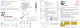
5.4.2 Pin Assignment
The plug connection is located on the back of the sensor. It is a 723 series 12-pin circular connector (flange plug) from
the company Binder.
This plug connector ensures optimum shielding as well as a high IP protection class. You will need a corresponding
cable socket with a shielding ring as the counterpart.
PC11xx cables with open ends and finished in various ways are optionally available, see Chap. A 1. The optionally avail-
able PC1100-x and PC1100/90-x supply/output cables can be used with drag chains and have the following bend radii:
- 47 mm (once)
- 116 mm (permanent)
Make sure that cable ends are not exposed. This could cause short circuits. Connecting input signals
to outputs can damage the sensor!
Sig-
nal
Pin PC1100-x cable color
Explanation
Comments, circuitry
H
M
G
J
K
A
L
B C
D
E
F
View: Solder side 12-pin cable
socket
Power supply and signal socket
M16x0.75; 12-pin
RX+ A white
RS422 input
(symmetrical)
Internally terminated with 120
Ohm
RX- B brown
TRIG C green Switching input
Trigger input, t
i
> 2 ms
I
OUT
D yellow Analog output 4 ... 20 mA
TX- E gray
RS422 output
(symmetrical)
Receiver terminated with 120
Ohm
TX+ F pink
+U
B
G red Supply voltage 10 ... 30 VDC, typ. 24 VDC
OUT1 H black Switching output 1
Switching behavior program-
mable: NPN, PNP, push-pull,
push-pull negated
I
max
= 50 mA
Protected against polarity
reversal, overload and exces-
sive temperature
OUT2 K
gray/
pink
Switching output 2
OUT3 M blue Switching output 3
GND L red/blue Supply ground
Reference potential for
switching outputs as well
GND J purple Signal ground
Reference potential for ana-
log output
Fig. 10 Pin assignment for power supply and signal, 12-pin plug connector
The ground lines are connected internally and are the reference potential for all voltage values given below. The limit
values for the voltages, loads and logic level comply with RS422 standards. All outputs are designed to be permanently
resistant to short circuits.
5.4.3 Supply Voltage
Nominal value 24 VDC (10 ... 30 V, P < 5.5 W (max. for Out1 ... Out3, I
out
and measurement mode active)
Only turn on the power supply after wiring has been completed.
Connect the G (red) and L (red/blue) inputs on the sensor to a 24 V voltage supply.
ILR2250
G
L
10 ...
30 VDC
Sensor
Pin
PC1100-x
cable color
Power supply Voltage supply only for measuring devices,
not to be used for drives or similar sources
of impulse interference at the same time.
MICRO-EPSILON recommends using the
optionally available PS2020 power supply,
see Chap. A 1, for the sensor.
G red
U
B
L red/blue Supply ground
Fig. 11 Supply voltage connection
HINWEIS

Page 17
Installation and Assembly
optoNCDT ILR2250
5.4.4 Analog Output
The sensor produces a current output of 4 ... 20 mA
i
The output may not be used continuously in short-circuit operation without a load resistor.
Continuous short-circuit operation leads to thermal overloading and thus causes the output to switch off automati-
cally.
Connect the D (yellow) and J (purple) inputs on the sensor to a measuring device.
D
I
out
J
ILR2250
G
L
10...
30 VDC
R
B
R
i
C
I
Sensor
Pin
PC1100-x
cable color
Comments
D yellow Analog output
J purple Signal ground
Fig. 12 Analog output switching
Analog Output Properties
- 4 ... 20 mA - Behavior when error reported: 3 mA
Load
R
B
< U
B
- 1 V / 20 mA
@10 V: R
B
< 450 Ohm
@24 V: R
B
< 1150 Ohm
@30 V: R
B
< 1450 Ohm
- R
i
30 Ohm
- Accuracy: 0.1 % FSO
- Distance range limits adjustable - Resistant to short circuits
- Resolution: 16 bit DA converter
The current impressed in the line is proportional to the measured distance. You can find more details on this in the Ana-
log Output section, see Chap. 6.6.
i
The measured values are always output via the analog output.

Page 18
Installation and Assembly
optoNCDT ILR2250
5.4.5 RS422 (with IF2001/USB Converter)
The RS422 interface can be used for configuration as well as for permanent data transmission, even over longer dis-
tances. It is interference-resistant and suitable for industrial applications. Distances of up to 1200 m are possible with a
twisted-pair cable.
For the connection between sensor and PC, the lines must be crossed.
i
Only disconnect or connect the sub-D connection between the RS422 and USB converter when no voltage is flow-
ing.
Characteristics
- Maximum input voltage RX+, RX- : ±14 V
max
internally terminated with 120 Ohm.
- Output voltage TX: ±2 V, differential at 2 x 50 Ohm
Parameter
- Baud rate 115200 baud - Start/stop bit: 1
- Data bits: 8 - Handshake: No
- Parity: None - Command protocol: ASCII
i
The RS422 interface is widely used in industrial applications.
Use a suitable USB converter, e.g. the IF2001/USB, see Chap. A 1, if your PC/Notebook only has USB ports.
Sensor Terminal, PLC,
IF2001/USB Converter
from MICRO-EPSILON
Symmetrical differen-
tial signals accord-
ing to EIA-422, not
electrically separated
from the voltage
supply.
Use a shielded cable
with twisted wires,
e.g. PC1100-x.
Pin Cable color
(Cable: PC1100-x)
Function Function
A White Rx+ Tx+
B Brown Rx- Tx-
E Gray Tx- Rx-
F Pink Tx+ Rx+
J Purple GND GND
Fig. 13 Crossed data lines on receive and transmit side

Page 19
Installation and Assembly
optoNCDT ILR2250
5.4.6 Trigger Input
The trigger input allows you to trigger a distance measurement using an external signal in the form of a voltage pulse.
PC1100-x
C
red/blue
L
Type 1
ILR2250
Type 2 Type 3
green
GND
+U
B
+U
B
47k
Trigger pulse: > 2 ms
High approx. 2/3 * +U
B
Low approx. 1/3 * +U
B
Internal pull-down resistor, an open input is detected
as Low.
Connect the input to +U
B
in order to trigger the
function.
Fig. 14 Basic circuit for triggering
Configure the desired triggering behavior
- with the sensorTOOL program
- or using ASCII commands (e.g. TRIGGER and TRIGGERLEVEL), see Chap. A 3.4.1.
The number of measured values received can be specified on the ILR2250 after a trigger pulse.
You can start level triggering with
- +U
B
at the trigger input for H-level triggering
- 0V at the trigger input for L-level triggering
5.4.7 Switching Output
The switching behavior (NPN, PNP, push-pull, push-pull negated) of the switching output depends on the programming.
With the digital switching output, objects to be measured can be monitored for thresholds being exceeded. A measure-
ment window must be parameterized for this. The parameters for the upper and lower switching threshold and for the
switching hysteresis can be freely selected, see Chap. 6.7.
NPN
+U
R
L
H
OUT1,2,3
H,K,M
PNP
OUT1,2,3
H,K,M
+U
B
Push-Pull
+U
B
OUT1,2,3
H,K,M
R
L
The outputs are not electrically separated.
The outputs are resistant to short circuits.
HT logic,
I
max
= 50 mA,
U
H, max
= 36 V saturation voltage at I
max
= 50 mA
Low-side < 1 V (output – GND) at 50 mA
High-side < 1 V (output – +U
B
) at 50 mA
Fig. 15 Basic circuit for switching output
Switching behavior
Name Output active (error) Output passive (no error)
NPN (Low side) GND
Approx. +U
H
PNP (High side)
+U
B
Approx. GND
Push-pull
+U
B
GND
Push-pull, negated GND
+U
B
Fig. 16 Switching output behavior
The switching output is activated when there is no target, when the target is too close/far or when no valid measurement
value can be determined.

Page 20
Operation
optoNCDT ILR2250
6. Operation
6.1 Getting Ready for Operation
Install the ILR2250 sensor as per the installation instructions, see Chap. 5.1.
Connect the system to the downstream display or monitoring units and to the voltage supply.
The sensor may only be connected to peripherals when it does not carry power, that is, only when the
supply voltage has been switched off.
The measurement laser starts when the supply voltage is applied if an active measurement (see LASER MEASURE ON)
has previously been saved in the sensor.
The sensor is ready to use after approx. 2 s, digital accuracy is immediate. The sensor typically requires a warm-up time
of 5 min for reproducible measurements via the analog output.
i
The sensor can be put in an autostart state. To do this, all desired parameters must be set and saved on the sensor.
If the sensor is then switched off during an active measurement, it immediately resumes the saved measurement
task once the power supply is connected again.
If the POWER LED is off, no power is being supplied.
6.2 Operation using sensorTOOL
The sensor must be connected to a PC/Notebook via an RS422 converter and the supply voltage must be applied.
The sensorTOOL program also finds connected sensors via a network. You can find this program online at https://www.
micro-epsilon.de/download/software/sensorTOOL.exe.
Launch the sensorTOOL program and click on the button.
The program will now search for connected ILR2250 sensors on the available interfaces.
Select a desired sensor. Click the Start Data Acquisition button.
Fig. 17 Auxiliary sensor search program
/