Page is loading ...


This page has been left blank intentionally.

TABLE OF CONTENTS
COMPONENT DESCRIPTION
OVERVIEW 1
HELMET SHELL 2
RETENTION (CHIN STRAP) ASSEMBLY 3
SUSPENSION (PAD/LINER) SYSTEM 4
COMPONENTS FOR MISSION-CONFIGURED HELMETS 5
HELMET PREPARATION
DETERMINING HELMET SIZE 6
CHECKING SUSPENSION (PAD/LINER) FIT — TEAM WENDY 8
CHECKING SUSPENSION (PAD/LINER) FIT — ADJUSTABLE 9
CHECKING SUSPENSION (PAD/LINER) FIT — 360° LINER 11
ADJUSTING RETENTION (CHIN STRAP) 12
INSTALLING WING-LOC ADAPTER 13
INSTALLING PICATINNY ADAPTER 14
MAINTENANCE
PREVENTIVE MAINTENANCE CHECKS 15
CLEANING 15
REPLACING SUSPENSION (PAD/LINER) — TEAM WENDY 16
REPLACING SUSPENSION (PAD/LINER) — ADJUSTABLE 17
REPLACING SUSPENSION (PAD/LINER) — 360° LINER 18
REPLACING RETENTION (CHIN STRAP) 19
CONTINUED ON NEXT PAGE


1
COMPONENT DESCRIPTION
OVERVIEW
The TBH-II is available in four sizes:
Small (SM), Medium (MD), Large (LG), and Extra Large (XL).
The TBH-II is available in two congurations:
The TBH-II is available in three cuts:
The TBH-II is available in two retention (chin strap) options:
The TBH-II is available in three suspension (pad/liner) options:
Clean
Mission-
Congured
Low-Cut Mid-Cut High-Cut
Team Wendy Adjustable
360° Liner
H-Nape
4-Point Head-Loc
X-Nape
4-Point Head-Loc

2
COMPONENT DESCRIPTION
HELMET SHELL
Trim Options
The helmet shell is available in three trim (cut ) options: Low-Cut, Mid-Cut, and High-Cut. These
options provide a balance between side coverage and integration with communication equipment.
Low-Cut
• Provides greatest degree of side protection
• Capable of integration with in-ear
communication systems
Mid-Cut
• Provides medium degree of side protection
• Average decrease in side protection coverage of helmet is 11%
• Capable of integration with in-ear and typical headset
communication systems
High-Cut
• Provides lowest degree of side protection
• Average decrease in side protection coverage of helmet is 35%
• Capable of integration with full range of passive and active noise
reduction headset communication systems
No holes
(non-NVG)
One hole Three holes
NVG Attachment Hole Options
Each helmet may be ordered with no holes, one hole, or three holes. The one-hole and three-hole
options allow the attachment of shrouds that hold Night Vision Goggle (NVG) mounting brackets.

3
COMPONENT DESCRIPTION
RETENTION (CHIN STRAP) ASSEMBLY
Two retention (chin strap) options are available: H-Nape Head-Loc and X-Nape Head-Loc. Both
options are available in Right Eye Dominate (RED) or Left Eye Dominate (LED) versions. Both options
feature a patented design that secures the helmet to the wearer’s head with four points of contact
(secured with ballistic bolts and T-nuts) to the helmet and direct lines from the helmet to the chin cup.
Ballistic Bolts and T-nuts
Ballistic bolts and T-nuts
simplify retention (chin strap)
replacement. They also
resist penetration and impact
spalling caused by handgun
and fragmentation threats.
Bolts
(four places)
Rail
(mission-congured
helmets only)
T-nuts
(four places)
H-Nape Head-Loc
X-Nape Head-Loc
Rear view
Rear view
Tri-Glide adjustment tabs
Installed in four places
to maximize adjustability
Head-Loc buckle
Maintains helmet security in all operations
Tri-Glide adjustment tabs
Installed in four places
to maximize adjustability
Head-Loc buckle
Maintains helmet security in all operations

4
COMPONENT DESCRIPTION
SUSPENSION (PAD/LINER) SYSTEM
Three suspension (pad/liner) system options are available: the Team Wendy 7-Pad Kit, the
Gentex Adjustable 8-Pad Kit, and the Gentex 360° Liner Kit. Each option is designed to
secure the helmet on the wearer’s head. All options (except Team Wendy) allow the movement
of the pads for the integration of communication systems with a low-prole headband.
Team Wendy 7-Pad Kit
Available in ¾-inch and 1-inch thicknesses for tting adjustments
Adjustable 8-Pad Kit
• Each pad consists of a fabric cover containing one thick foam pad and
two thinner foam pads
• One or both thinner foam pads can be removed for tting adjustments
360° Liner Kit
• Consists of a foam impact liner, a front pad, and a set of ventilated
comfort pads
• Helmet ships with ½-inch thick comfort pads installed; ¼-inch thick
comfort pads and ¾-inch thick comfort pads are also included for
tting adjustments
Cover (closed) Cover (opened)
Remove thinner
foam pad(s) to
adjust thickness
PAD
DETAIL
Exterior view

5
COMPONENT DESCRIPTION
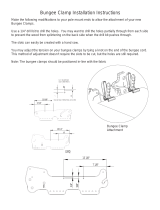
COMPONENTS FOR MISSION-CONFIGURED HELMETS
Standard components for the Mission-Congured TBH-II include the Skeleton Shroud, Skeleton
Rails, Carabiner Bungees, Hook Bungees, the Exterior Velcro Kit, two Picatinny Adapters,
and two Wing-Loc Adapters. Optional styles of shrouds and rails are also available.
STANDARD COMPONENTS
Skeleton Shroud
• Compatible
with most NVG
mounting brackets
• Also holds lights,
cameras, and
other accessories
Carabiner Bungees
• Reduce rattle and
vibration of NVGs
• Attach quickly and
easily to shroud
and rails
Skeleton Rails (two places)
• Hold various items such as
visors, mandibles, lights,
and cameras
• Attach to helmet with
retention hardware
Exterior Velcro Kit
• Permit attachment of
head-borne accessories
• Five-piece kit in sizes
that match helmet sizes
OPTIONAL COMPONENTS
Picatinny Adapters
Attach items to rails
Hook Bungees
Wing-Loc Adapters
Attach items to rails
VAS Shroud ARC Rails

6
HELMET PREPARATION
Helmet preparation includes determining helmet size, checking the t of the pad suspension, and
adjusting the chin strap.
DETERMINING HELMET SIZE
Helmet sizes are Small, Medium, Large, and X-Large. To determine size, you must (1) measure and
record the wearer’s head length, (2) measure and record the wearer’s head breadth, (3) measure
and record the wearer’s head circumference, and (4) select the helmet size based upon the
parameters in the tables on Page 7.
Tools/Equipment Needed:
• Caliper • Ruler • Tape measure
MEASURE HEAD LENGTH
Use a caliper and a ruler to measure the distance
(to the nearest
⁄ inch) from the point between
the eyebrows to the back of the head. Ensure
that the caliper touches the skin lightly and does
not indent the skin. Record the measurement.
MEASURE HEAD BREADTH
Use a caliper and a ruler to measure the maximum
head width (to the nearest
⁄ inch) above the ears.
Ensure that the caliper touches the skin lightly and
does not indent the skin. Record the measurement
.
1
2
CONTINUED ON NEXT PAGE
Between
eyebrows
Back of
head
Caliper
Caliper
Ruler
Ruler
HEAD LENGTH
HEAD BREADTH

7
HELMET PREPARATION
MEASURE HEAD CIRCUMFERENCE
Use a tape measure to determine the maximum head
circumference (to the nearest
⁄ inch) above the ears.
Ensure that the caliper touches the skin lightly and
does not indent the skin. Record the measurement
.
SELECT HELMET SIZE
Referring to the tables below (for inches or millimeters), select the helmet size based on head length,
head breadth, and head circumference.
INCHES:
Helmet Size Head Length (in.)
Head Breadth
(in.) Head Circumference (in.)
Small (S)
Up to 7¼ Up to 6½ Up to 21¼
Medium (M)
7¼ to 7¾ 6½ 21¼ to 22½
Large (L)
7¾ to 8¼ 6½ 22½ to 23½
Extra Large (XL)
8¼ and greater 6½ and greater 23½ and greater
MILLIMETERS:
Helmet Size Head Length (mm)
Head Breadth
(mm) Head Circumference (mm)
Small (S)
Up to 184 Up to 165 Up to 539
Medium (M)
184 to 196 165 539 to 571
Large (L)
196 to 209 165 571 to 596
Extra Large (XL)
209 and greater 165 and greater 596 and greater
NOTE: For best sizing, wear the helmet with all forms of equipment that will be used during an
operation. Include length of hair, balaclava, cold-weather gear, protective mask, and communication
equipment. If unable to obtain size with actual helmets, select largest size helmet based on any of the
three measurements obtained using a caliper and/or tape measure.
3
4
Tape measure
HEAD CIRCUMFERENCE

8
HELMET PREPARATION
CHECKING SUSPENSION (PAD/LINER) FIT — TEAM WENDY
PLACE THE HELMET ON THE HEAD.
Leave the chin strap loose for now. Allow the helmet to settle on the head for a few minutes. Ensure
that the front pads are just above the eyebrows. If necessary, adjust the t as follows:
• Helmet too high or too tight: Remove the pads and install a thinner pad set (ordered separately)
as shown. Re-check the t.
• Helmet too low or too loose: Remove the pads and install a thicker pad set (ordered separately)
as shown. Re-check the t.
NOTE: The Team Wendy pad kit is available in the following thicknesses: ¾-inch-thick pads, and
1-inch-thick pads (with a ¾-inch-thick crown pad). The helmet is supplied with one of these pad sets.
The user must order other pad sets separately if needed.
PROCEED TO ADJUSTING RETENTION (CHIN STRAP) — PAGE 12.
1
Ensure the helmet is properly adjusted for a snug, secure t at all times when the helmet
is worn. Failure to do so can result in an unstable helmet that will not protect the wearer.
2
TEAM WENDY PADS
Crown
Front/Rear
Lateral
Lateral
Lateral
Lateral
Front/Rear

9
HELMET PREPARATION
CHECKING SUSPENSION (PAD/LINER) FIT — ADJUSTABLE
PLACE THE HELMET ON THE HEAD.
Leave the chin strap loose for now.
Allow the helmet to settle on the head for a few minutes.
CHECK THE HELMET HEIGHT.
The front pads should be just above the
eyebrows. If the helmet is too high, have
the wearer remove the helmet. Adjust the
height as follows:
• Remove the two crown pads, noting
their position inside the helmet.
• Remove one or both ¼-inch-thick foam
pads from each pad cover.
• Reinstall both crown pads (with at
least the ½-inch-thick foam pad
inside each one) in the helmet in the
same positions from which they were
removed. Ensure that the opening
in each crown pad cover faces the
hook fasteners inside the helmet.
• If the wearer uses a headset, space
the crown pads to accommodate the
headband of the headset.
• Have the wearer don the helmet.
Recheck the helmet height.
Ensure that the helmet is properly adjusted for a snug, secure t at all times when the helmet
is worn. Failure to do so can result in an unstable helmet that will not protect the wearer.
Each pad contains one ½-inch-thick foam pad and two ¼-inch-thick foam pads inside
the cover. For impact protection and helmet stability, you must keep all ½-inch-thick
foam pads inside the covers and all pads properly installed in the helmet when the
helmet is worn. Remove the ¼-inch-thick pads only where necessary to adjust the t.
1
2
CONTINUED ON NEXT PAGE
ADJUSTABLE PADS
CROWN PAD DETAIL
Crown
Crown
¼ inch thick
foam pads
Pad cover
Opening
½ inch thick
foam pad

10
HELMET PREPARATION
CHECK THE OVERALL HELMET FIT
Ensure that the helmet t is snug and secure, yet comfortable. If the helmet is too tight, have the
wearer remove the helmet, adjust the bottom pads as follows:
• Remove the bottom pads from the helmet as needed, noting their position inside the helmet.
• Remove one or both ¼-inch-thick foam pads from the pad cover.
• Reinstall the bottom pads (with at least the ½-inch-thick foam pad inside each
one) in the helmet in the same positions from which they were removed. Ensure that
the opening in each pad cover faces the hook fasteners inside the helmet.
• Have the wearer don the helmet again. Recheck the t.
PROCEED TO ADJUSTING RETENTION (CHIN STRAP) — PAGE 12.
3
4
ADJUSTABLE PADS
¼ inch thick
foam pads
Pad cover
Opening
½ inch thick
foam pad
BOTTOM PAD DETAIL
Bottom
Bottom
Bottom
Bottom
Bottom
Bottom

11
HELMET PREPARATION
CHECKING SUSPENSION (PAD/LINER) FIT — 360° LINER
PLACE THE HELMET ON THE HEAD.
Leave the chin strap loose for now. Allow the helmet to settle on the head for a few minutes before
checking the t. Ensure that the front pad is just above the eyebrows. If necessary, adjust the t
as follows:
• Helmet too high or
too tight: Remove the
½-inch-thick comfort pads
and install the ¼-inch-
thick pads as shown.
Re-check the t.
• Helmet too low or too
loose: Remove the
½-inch-thick comfort pads
and install the ¾-inch-
thick pads as shown.
Re-check the t.
NOTE: The 360° Liner kit is shipped with the ½-inch-thick comfort pads installed. The ¼-inch thick
comfort pads and the ¾-inch-thick comfort pads are included in the package. You can use a combination
of pad thicknesses to achieve the best comfort and t.
IF USING A HEADSET, CONFIGURE THE PADS ACCORDINGLY.
Remove the comfort pad
located at the crown.
PROCEED TO ADJUSTING RETENTION (CHIN STRAP) — PAGE 12.
Ensure the helmet is properly adjusted for a snug, secure t at all times when the helmet
is worn. Failure to do so can result in an unstable helmet that will not protect the wearer.
1
3
2
¼ inch thick
comfort pads
½ inch thick
comfort pads
¾ inch thick
comfort pads
Pad removed

12
HELMET PREPARATION
ADJUSTING RETENTION (CHIN STRAP)
BUCKLE THE CHIN STRAP.
With both hands, adjust the two rear slide adjustments simultaneously until the straps are snug.
With both hands, adjust the two front slide adjustments simultaneously until the straps are snug.
NOTE: This technique works best if you only hold the slide adjustments and don’t touch the straps.
CHECK THE HELMET STABILITY.
Attempt to rock the helmet back and forth on the head. If the helmet rocks back and forth, it is not stable.
Adjust the straps further until the helmet is stable.
NOTE: Release the buckle to remove the helmet.
Ensure that all helmet adjustment mechanisms are properly adjusted for a snug, secure t at
all times when the helmet is worn. Failure to do so can result in an unstable helmet that will
not protect the wearer.
1
2

13
HELMET PREPARATION
INSTALLING WING-LOC ADAPTER
ATTACH THE ACCESSORY TO THE ADAPTER.
Attach the desired accessory to the Wing-Loc adapter by inserting the screws through the adapter holes
and tightening the screws into the accessory holes.
INSTALL THE ADAPTER ONTO THE RAIL.
Pinch the tabs, and slide the Wing-Loc adapter and slide the adapter (with accessory attached) to the
preferred position on the rail.
1
2
Screws
Wing-Loc
Adapter
Accessory
Pinch tabs;
slide adapter to
preferred position

14
HELMET PREPARATION
INSTALLING PICATINNY ADAPTER
INSERT THE ADAPTER INTO THE RAILS
Loosen the screw on the Picatinny adapter. Place the adapter within the grooves of the rail, and slide the
adapter into the rail as far as possible.
POSITION THE ADAPTER WITHIN THE RAILS.
Pinch the tab, and slide the adapter to the preferred position. Ensure that the screw is aligned with the
rail slot in the preferred position, and tighten the screw.
1
2
Loosen screw
Slide adapter into rail
Tighten screw
Pinch tab;
slide adapter to
preferred position

15
MAINTENANCE
PREVENTIVE MAINTENANCE CHECKS
Perform preventive maintenance tasks for each component as described in the table below.
Component Examine for: Helmet is not ready if:
Helmet Shell
• Gouges, scrapes, cracks,
delamination or other damage
extending below the paint
• Loose or damaged edging
• Gouges, scrapes, cracks,
delamination or other damage
extends below the paint
• Edging is loose or damaged
Suspension (Pad/Liner)
• Cuts, tears or other damage to
outer fabric or inner foam
• Exposed foam
• Pads that do not return to
original shape when squeezed
• Worn hook/pile fasteners
• Pads are torn, cut, or
otherwise damaged
• Foam is exposed
• Pads do not return to original
shape when squeezed
• Hook/pile fasteners fail to hold
pads in place
Retention (Chin Strap)
• Cuts, frays or other damage; or
loose or damaged stitching in
the webbing
• Missing, cracked, worn, or
damaged Head-Loc buckle
or Tri-Glide adjustment
• Loose or missing screw or T-nut
• Webbing is frayed more than
½ inch or has a discernible cut; or
stitching is loose or damaged
• Head-Loc buckle or Tri-Glide
adjustment is missing,
cracked, or worn.
• Screw or T-nut is
loose or missing
Shroud, rails, or bungees
(mission-congured helmets)
• Loose or missing hardware • Hardware is loose or missing
CLEANING
Perform cleaning tasks for each component as described in the table below.
Component Cleaning Procedure
Helmet Shell
Clean with mild soap and water; use a soft brush. Allow to dry.
Suspension (Pad/Liner)
Spot-clean with mild soap and water; use air pressure to remove dust and dirt.
Pads may be machine-washed, but do not machine-dry; allow to air-dry.
Retention (Chin Strap)
Same as suspension (pad/liner)
Shroud, rails, or bungees
(mission-congured helmets)
Wipe with damp cloth

16
MAINTENANCE
REPLACING SUSPENSION (PAD/LINER) — TEAM WENDY
REMOVE THE EXISTING PADS.
When removing the pads, note their position and orientation in the helmet. Also note the pad
thickness: the Team Wendy version has ¾-inch-thick or 1-inch-thick pads.
INSTALL THE REPLACEMENT PADS.
Use the same pad thickness, and install the pads in the same position and orientation as the
previous pads.
Don the helmet, and check the t in accordance with
Page 8 and Page 12
. Make any
necessary adjustments.
1
2
Front/Rear
Crown
Lateral
Lateral
Lateral
Lateral
Front/Rear
/