Page is loading ...

DUAL VISOR
SPH-5
â
HELMET ASSEMBLY
Fitting, Operation, and
Maintenance Instructions
noi ta ro proC XETNEG 5002 ©

CONTENTS
INTRODUCTION AND GENERAL DESCRIPTION .............. 1
HELMET SIZING ................................ 2
HELMET FITTING AND OPERATION ..................... 3
INSPECTIONS .................................12
CLEANING ...................................14
REPLACEMENT PROCEDURE 1:
ENERGY-ABSORBING LINER AND TPL ...................14
REPLACEMENT PROCEDURE 2: RETENTION ASSEMBLY.........15
REPLACEMENT PROCEDURE 3: EARCUPS AND EARPHONES ......16
REPLACEMENT PROCEDURE 4: MICROPHONE ASSEMBLY .......18
REPLACEMENT PROCEDURE 5: COMMUNICATIONS CORD .......19
REPLACEMENT PROCEDURE 6: DUAL VISOR ASSEMBLY ........21
ILLUSTRATED PARTS BREAKDOWN ....................24
OTHER VISOR STYLES AVAILABLE .....................26

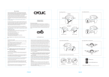
INTRODUCTION AND GENERAL DESCRIPTION
This booklet provides operation and maintenance instructions, as well as an
illustrated parts breakdown (IPB) on page 24, for the GENTEX® SPH-5® Helmet
Assembly (Figure 1).
The SPH-5 is a lightweight helmet assembly providing head protection, noise
reduction, and communication enhancement for helicopter personnel. It consists
of an impact-resistant helmet shell, a polystyrene energy-absorbing liner, a
preformed thermoplastic liner (TPL®) that allows for custom-fitting, a yoke-style
retention assembly (including a chinstrap and a nape strap — both adjustable),
sound-attenuating earcups, a dual visor assembly, and a communications
assembly featuring a boom-mounted microphone and dual earphones. The
helmet is available in four sizes: small, regular, X-large, and XX-large. (Other
visor assembly styles are available and are listed at the end of this booklet.
Contact Gentex Corporation for more information.)
Figure 1. SPH-5 Helmet Assembly
GENTEX®, SPH-5®, and TPL® are registered trademarks of GENTEX Corporation.
1
HELMET
SHELL
BOOM AND
MICROPHONE
EARCUP
ASSEMBLY (2)
RETENTION
ASSEMBLY
DUAL VISOR
ASSEMBLY
ENERGY-ABSORBING
LINER
TPL

HELMET SIZING
Helmet sizing is based on head circumference. (Figure 2 shows how the
crewmember’s head is measured for circumference.) Below are sizing
parameters.
HELMET SIZE MAXIMUM HEAD CIRCUMFERENCE (INCHES)*
Small < 21.5
Regular 21.5 - 22.4
X-Large 22.4 - 23.5
XX-Large > 23.5
• These are rule-of-thumb measurements. At times, the next larger or smaller
size may be required to achieve a satisfactory fit.
Figure 2. Head Circumference for Helmet Sizing
2
TAPE MEASURE

HELMET FITTING AND OPERATION
In this procedure, you will ensure that the helmet is properly fitted to the
crewmember. You will also familiarize the crewmember with operation
procedures, including donning and doffing the helmet (Steps 1 and 8
respectively), adjusting the nape strap (Step 2), fastening and unfastening
the chinstrap (Steps 3 and 7 respectively), operating the visors (Step 4), and
operating the communications system (Step 5).
1. Have the crewmember don the helmet as follows:
CAUTION
Spread the helmet slightly – just enough to allow ease of
donning. Excessive spreading may damage the helmet.
a. Grip the retention
assembly below the
earcups as shown in
Figure 3, view A.
b. Spread the sides of the
helmet slightly and
position the front edge
firmly against the
forehead as shown in
Figure 3, view B.
c. Roll the helmet back and
down onto the head.
Press the helmet firmly
downward with both
hands to ensure that the
helmet is properly seated
on the head and the ears
are surrounded by the
earcups. (The earcups
can be rotated for
optimum fit.)
d. Check the distance
between the eyebrows
and the edge of the
helmet shell; it should be
approximately (but no
more than) 3/4” for
optimum field of view.
(Continued on next page)
3
Figure 3. Donning Helmet
A
B

WARNING
For helmet stability, always tighten the nape strap and the
chinstrap as snugly as possible when wearing the helmet.
Failure to do so may result in injury.
2. Have the crewmember tighten the rear of the retention assembly by
adjusting the hook-and-pile closure and tightening the nape strap
through the adjustment buckle. (See Figure 4.)
Figure 4. Rear of Retention Assembly
3. Have the crewmember fasten the chinstrap as follows:
a. If not already done, insert the snap end of the chinstrap through the
D-ring on the right side (as worn) of the retention assembly and fasten
the snap as shown in Figure 5, view A.
b. Feed the other end of the chinstrap through the D-rings on the left side
of the helmet.
c. Split the D-rings, loop the chin strap end back through inner D-ring, and
pull the chin strap through both D-rings as shown in Figure 5, view B.
d. Tighten the chinstrap to the desired tension. Once the desired tension
is achieved, the chinstrap can be fastened and unfastened via the snap.
Figure 5. Fastening and Adjusting Chinstrap
4
HOOK-AND-PILE CLOSURE
NAPE STRAP
ADJUSTMENT BUCKLE
A B

4. Have the crewmember lower and raise the visors as follows (to test
operation and clearance):
NOTE
Visor knobs can be moved to either side of the visor housing
depending on crewmember preference. See Page 23 for
instructions.
Inner Visor
a. Unlock the visor by
pushing the actuator
knob downward as
shown in Figure 6,
view A.
b. While holding the knob
down, raise or lower
the visor by sliding the
knob along the track.
c. Release the actuator
knob in any of the
visor lock positions.
Outer Visor
a. Unlock the outer
visor by turning the
center lock knob
counterclockwise as
shown in Figure 6,
view B.
b. Rotate the visor by
sliding the knob along
the housing slot.
c. Lock the visor by
turning the knob
clockwise.
(Continued on next page)
5
Figure 6. Raising and Lowering Visors
A
B

CAUTION
In Step 5, be sure to loosen the knurled nut on the swivel
assembly before you rotate the boom assembly. Any attempt
to rotate the boom assembly without loosening the knurled nut
can cause the mounting hole in the helmet shell to become
rounded; consequently, the boom assembly will not be held in
place.
5. Referring to Figure 7, have the operator operate and adjust the
communications system as follows:
a. Loosen the boom swivel assembly by rotating the knurled nut
counterclockwise until the boom is free to move.
b. Rotate the boom up or down as needed.
c. Slide the boom backward or forward as needed.
d. Tighten the swivel by rotating the knurled nut clockwise.
e. Adjust the front of the boom as needed.
f. Loosen the knurled screw on the microphone, and adjust the
microphone as needed. Tighten the screw.
Figure 7. Communications System Points of Operation
6
CONNECTOR
MICROPHONE
PLUG
KNURLED NUT ON
BOOM SWIVEL ASSEMBLY
KNURLED SCREW
ON MICROPHONE
MICROPHONE
FRONT OF BOOM

6. Evaluate the fit according to the following criteria:
a. The earcups should surround the ears completely.
b. The earseals should be compressed to the greatest degree possible
without discomfort.
c. The overall fit should be comfortable; no hot spots or pressure points
should exist.
NOTE
After evaluating the fit, you will unfasten the chinstrap and doff
the helmet as instructed in Steps 7 and 8. If the helmet fulfills
all of the criteria listed in Step 6, mark and store the helmet as
required. If the earcups do not surround the ears completely,
refer to “Adjustment #1: Earcup Centering.” If the earseals are
not sufficiently compressed, refer to “Adjustment #2: Earseal
Compression.” If the overall fit is too tight or too loose, or hot
spots or pressure points exist, refer to “Adjustment #3: TPL
Custom-Fitting.”
7. Have the crewmember unfasten the chinstrap by unsnapping the strap and
disengaging the strap through the right-hand (as worn) D-ring.
8. Have the crewmember doff the helmet as follows:
CAUTION
Spread the helmet slightly – just enough to allow ease of
doffing. Excessive spreading may damage the helmet.
a. Hook the thumbs in the earcups and spread the helmet at the earcup
area.
b. Roll the helmet upward and rearward as shown in Figure 8.
Figure 8. Doffing Helmet
7

Adjustment #1: Earcup Centering
1. If the ears are not centered within the earcups, rotate the earcups within the
retention assembly. Don the helmet, tighten the chinstrap, and recheck the
earcup centering.
2. If the ears are not centered within the earcups after the earcups have been
rotated, unfasten the chinstrap, doff the helmet, and remove the TPL as in
Replacement Procedure 1, Step 1 (Page 13). Have the crewmember don
the helmet and hold it so that the edge of the helmet is approximately 3/4"
above the eyebrows. With the helmet in this position, check the location of
the earcups. If the earcups now completely surround the ears, this indicates
a need for TPL custom-fitting. Have the crewmember doff the helmet.
Perform the TPL Custom Fitting Procedure. This should result in a proper
fit of the helmet and the earcups.
3. If the ears are not centered in the earcups after the TPL has been removed,
or you must raise or lower the helmet to achieve proper centering, you will
have to adjust the retention straps upward or downward. To obtain access
to these straps, you must remove the energy-absorbing liner and at least one
earcup. Follow these steps:
a. Remove either earcup from the retention assembly as in Replacement
Procedure 3, Steps 2 and 3 (Page 16).
b. Remove the energy-absorbing liner as in Replacement Procedure 1,
Steps 3 and 4 (Page 14).
c. Adjust the retention strap
holes upward or downward as
necessary. The front and
center straps allow for upward
or downward adjustment; the
rear straps allow for forward
or rearward adjustment. (See
Figure 9.) Remove the
attachment hardware. Apply
one or two drops of white
Weldwood glue #281 or
equivalent to the first two
threads of each screw and
reinstall the hardware in the
selected holes as needed.
d. Reinstall the energy-
absorbing liner as in
Replacement Procedure 1,
Step 5 (Page 14).
e. Reinstall the earcups as in Replacement Procedure 3, Steps 10 -11
(Page 17).
8
Figure 9. Retention Straps
FRONT STRAPS
CENTER
STRAPS
REAR STRAPS

f. Reinstall the TPL as in Replacement Procedure 1, Step 7 (Page 14).
g. Have the crewmember don the helmet and fasten the chinstrap. If the
ears are now centered in the earcups, remove and store the helmet as
required. If not, readjust the retention straps as necessary until the ears
are centered in the earcups.
Adjustment #2: Earcup Compression
1. If the earseals are not sufficiently
compressed, doff the helmet and
tighten the helmet cross straps. Two
cross straps are located behind each
earcup; each cross strap has a loop.
To tighten each cross strap, insert a
finger into the loop and move the loop
toward the bottom of the shell. (See
Figure 10.) Don the helmet, tighten
the chinstrap, and recheck the earseal
compression.
2. If the earseals are not sufficiently compressed after the cross straps have
been tightened, doff the helmet and add earcup spacer pads behind each
earcup as required. The earcup spacer pad set supplied with each helmet
consists of four pads (two ½" thick and two 1/4" thick) and pressure-sensitive
pile fastener. Install the pads as follows:
a. Peel the backing from one pressure-sensitive pile fastener and apply the
adhesive side of the fastener directly to the back of one earcup. Repeat
for the other earcup.
NOTE
Spacer pads may be installed whole or cut to any size or shape
needed to increase or balance earcup compression. See
Figure 11 for examples.
9
Figure 10. Cross Straps
CROSS
STRAPS
Figure 11. Earcup Spacer Pad Uses
INCREASE
OVERALL
PRESSURE
BALANCE TOP OR
BOTTOM PRESSURE
BALANCE FRONT
OR REAR PRESSURE
BALANCE TOP/BOTTOM OR
FRONT/REAR PRESSURE
BALANCE CORNER
PRESSURE
(Continued on next page)

b. Attach spacer pad(s) to an earcup with the hook side of the pad facing
the pile fastener on the earcup. Ensure that the fasteners are firmly
attached. Repeat for the other earcup.
3. Don the helmet, tighten the chinstrap, and recheck the earseal compression.
Add more spacer pads if needed until earseals are sufficiently compressed
and a uniform, comfortable earcup fit is attained.
Adjustment #3: TPL Custom-Fitting
If the helmet does not fit properly, i.e. it has hot spots or pressure points or the fit
is too tight or too loose, remove the helmet and custom-fit the TPL following the
Custom-Fitting Procedure below.
Tools and Equipment Required
1. Oven - Capable of stabilized sustained temperature of 200°F ± 5°F
(93.3°C ± 2.8°C) with thermometer and internal volume of approximately 1.5
cubic feet or equivalent
2. Ruler
3. Timer or equivalent
4. Masking Tape
STEP RESULT/REMARKS
1. Set oven rack to lowest position; heat
oven to 200°F ± 5°F (93.3°C 2.8°C).
- Ensure oven stabilizes at
approximately 200°F.
- Do not remove TPL cover; heat as a
unit.
2. Place TPL fabric side down in
center of rack in heated oven.
CAUTION
ENSURE THAT NO UPPER BURNER
ACTIVATES DURING HEATING, OR
TPL PLASTIC LAYERS WILL MELT.
- Preview Steps 5 through 10 so that
they may be completed within 30
seconds.
3. Allow oven to stabilize at temperature
listed in Step 1 before starting timed
sequence.
- In helmet, cover hook fasteners on
rear of energy-absorbing liner with
masking tape to ease TPL positioning.
4. Heat TPL for approximately 10
minutes.
- Set timer, stopwatch, or equivalent.
- Check TPL every two or three minutes
to ensure plastic layers are not
melting.
- Describe procedure to crewmember
being fitted.
5. Remove TPL from oven. - Steps 5 - 10 should be completed
within 30 seconds.
10

STEP RESULT/REMARKS
WARNING
TPL PLASTIC WILL BE HOT TO
TOUCH. AVOID BURNING HANDS.
WEAR GLOVES IF
NECESSARY.
6. Squeezing sides of TPL together to
clear earcups, place TPL in helmet
with label and holes facing front.
7. Align TPL to protrude approximately
1/4" past energy-absorbing liner.
- Ensure TPL is centered within the
helmet.
- Do not be concerned if rear of TPL
extends beyond energy-absorbing liner.
CAUTION
HOT TPL PLASTIC LAYERS ARE
SOFT. WHEN PERFORMING STEP 8,
DO NOT PRESS TOO HARD IN ANY
ONE AREA; THIS WILL DEFORM TPL.
8. Position TPL crown into helmet.
9. Have crewmember don helmet. - To ensure TPL does not bunch up in
rear during donning, hold rear of TPL
against energy-absorbing liner while
crewmember dons helmet. (See
Figure 12.)
10. With hands on top of helmet, press
down until ears are centered in
earcups. Hold for three to five
minutes.
(Continued on next page)
- Ensure entire ear is surrounded by
earcup; press helmet down further if
necessary.
- Chinstrap may be fastened to hold
helmet in position.
- Ensure helmet shell is centered
comfortably on head.
- Lower visors to check centering and
nose clearance.
11
Figure 12. Donning Helmet with Heated TPL

STEP RESULT/REMARKS
11. Check distance between eye-
brow and edge of helmet shell.
- Distance should be approximately (but no
more than)
3
/
4²
for optimum field of view.
12. Release pressure and remove
helmet.
- Remove tape from hook fasteners
covered in Step 3.
13. Have crewmember don helmet. - Adjust earcups; tighten nape strap and
chinstrap.
14. Check fit. - Check for hot spots and pressure points. If
none exist, remove and store helmet as
required. If the helmet does not fit
properly, remove TPL and repeat fitting
procedure.
WARNING
In some cases, it will be necessary to remove
one or more plastic layers to achieve an
optimum fit. If removing layers, at least two
layers must be retained or helmet stability will
not be maintained. Do not remove outer
layers; remove inner layers only. The TPL will
not fit into the EA liner properly if outer layers
are removed.
NOTE
The TPL cloth cover can be laundered or dry cleaned. Before removing
cover in preparation for cleaning, note the direction in which the cover is
facing. Note especially the “Y” seams on the cover; the double leg of the
“Y” should face the front of the TPL and the single leg should face the
rear. Replace the two-sided tape after cleaning, and install cover on
layers in the proper direction.
INSPECTIONS. Inspections consist of preflight and postflight inspections by the
user, and periodic inspections by the technician.
Preflight Inspection. Prior to each flight, the user should inspect the helmet
assembly to see that it is in good working order. This inspection should ensure
that:
1. The helmet, liners and earcup assemblies have been fitted properly.
2. The chinstrap and nape strap are adjusted properly and the retention
assembly is attached to the helmet with the screws tightened securely.
3. The visors operate properly and are clean and free of scratches and cracks.
4. All communication components have been installed properly and the
earphones and microphone operate properly.
5. The overall condition of the helmet has been checked for serviceability.
Postflight Inspections. After each flight, the user should note any component
malfunction or damage to the helmet resulting from operational use. Affected
components should be replaced as specified in Table 1.
Periodic Inspection. Crewmembers are responsible for ensuring that their
helmet assembly has been inspected, cleaned or replaced as necessary.
Periodic or scheduled inspections should occur at least every 180 days or as
required. Refer to Table 1 for applicable replacement procedures.
12

Table 1. Periodic Inspection
COMPONENT INSPECT FOR: APPLICABLE PROCEDURE
Helmet Shell Cracks, holes, warping.
Cleanliness.
Remove all components; install
components in replacement shell.
Clean per instructions on the next
page.
Energy-
Absorbing
Liner
Worn or loose hook
fasteners.
Gouges, cracks,
indentations.
Remove liner as in Replacement
Procedure 1, Page 14. Replace
fasteners; reinstall liner.
Replace liner as in Replacement
Procedure 1.
TPL Torn or damaged areas.
Loose bond at edges.
Worn cover.
Replace TPL as in Replacement
Procedure 1, Page 14.
Remove TPL as in Replacement
Procedure 1; replace two sided
tape attaching cloth cover to plastic
layers; reinstall TPL.
Remove TPL from helmet as in
Replacement Procedure 1; replace
TPL cover, reinstall TPL.
Earcup
Assembly
Cracked cup, broken or
missing tab, torn earseal,
worn earphone holder or
spacer pad, or failed
earphone.
Cleanliness.
Remove earcup as in Replacement
Procedure 3, Page 16; replace
parts as necessary; reinstall
earcup.
Clean per instructions on the next
page.
Retention
Assembly
(including
nape strap
and chinstrap)
Frayed or torn fabric,
loose stitching, corroded
or bent buckles or snap.
Cleanliness.
Replace as in Replacement
Procedure 2, Page 15.
Clean per instructions on the next
page.
Microphone,
Boom, Swivel
Assembly
Failed microphone;
damaged or worn swivel
or boom.
Replace assembly as in
Replacement Procedure 4,
Page 18.
Microphone
Cord,
Connector
Cuts, cracks, deteriorated
insulation, general
damage.
Replace as in Replacement
Procedure 5, Page 19.
Visor
Assembly
Cracks, scratches, loose
knobs.
Cleanliness.
Replace as in Replacement
Procedure 6, Page 21
Clean per instructions on the next
page.
13

CLEANING
Components of the SPH-5 helmet assembly can be cleaned as follows:
Helmet shell and visor assembly (including visors, housing, tracks, and knobs):
Wipe with clean, soft cloth dampened with mild soap solution; rinse with clean
water and allow to air dry.
Earcups, cords, retention assembly: Wipe with damp cloth; allow to air dry
thoroughly.
TPL cloth cover: Machine wash (gentle cycle) or hand wash with warm water and
soap; allow to air dry.
TPL plastic layers: Hand wash with soap and water; allow to air dry.
REPLACEMENT PROCEDURE 1:
ENERGY-ABSORBING LINER AND TPL
1. Squeezing the sides of the TPL together to clear the earcups as shown in
Figure 13, remove the TPL from the helmet.
2. Remove at least one earcup from the retention assembly as in Replacement
Procedure 3, Steps 1-3 (Page 16).
3. Insert a flat-tip screwdriver or a tongue depressor between the energy-
absorbing liner and the helmet shell in the front and rear and disengage the
hook-and-pile fasteners holding the liner in place.
4. Apply slight pressure to the energy-absorbing liner from the rear and slide it
out through the front of the helmet.
NOTE
Before you install the replacement energy-absorbing liner, ensure that
its hook-fastener tabs are in place in the front and rear.
5. Install the replacement energy-absorbing liner by inserting the rear of the
liner into the front of the helmet and applying slight pressure to position the
liner in the helmet. Ensure that the hook-and-pile fasteners are engaged.
6. Reinstall the earcup(s) as in Replacement Procedure 3, Steps 10 -11
(Page 17).
7. Referring to Figure 13, squeeze the sides of the TPL together to clear the
earcups and attach the TPL to the energy-absorbing liner in the helmet.
Ensure that the label and holes in
the plastic layers (as well as the
double leg of the “Y” seam on the
cloth cover) are positioned toward
the front of the helmet. Center the
TPL in the energy-absorbing liner.
The TPL should protrude
approximately 1/4" past the front
edge of the energy-absorbing
liner.
8. Recheck the helmet fit.
14
Figure 13. Removing/Replacing TPL

REPLACEMENT PROCEDURE 2:
RETENTION ASSEMBLY
1. Squeeze the sides of the TPL together and remove it from the helmet.
2. Remove the earcups from the retention assembly as in Replacement
Procedure 3, Steps 1-3 (Page 16).
3. Remove the energy-absorbing liner as follows as in Replacement
Procedure 1, Steps 3 and 4 (Page 14).
NOTES
• Prior to removing attaching hardware from retention straps, note which
strap holes are used for attachment. These same holes must be used
when installing new retention assembly.
• The front and center straps on both sides share attaching hardware with a
helmet shell cross strap. The left rear strap shares hardware with the
communications cord strain relief plate. When removing hardware from
any of these points, note position and order of attachment to ensure
correct installation (see Figure 14).
4. Remove the six screws (three each side), washers, and posts attaching the
retention assembly to the helmet shell and remove the retention assembly
from the helmet.
15
Figure 14. Retention Assembly Attachment
CROSS
STRAP
RETENTION
STRAP
POST
HELMET
SHELL (REF.)
WASHER
SCREW
HELMET
SHELL (REF.)
WASHER
SCREW
COMM.
CORD
RETENTION
STRAP
POST
STRAIN
RELIEF
(Continued on next page)

5. Align the straps of the replacement retention assembly within the helmet and
install the retention assembly using hardware removed in step 3. Applying
Weldwood glue #281 to the first two threads of each screw, insert the screws
through holes previously used. Tighten the screws securely, but do not
overtighten.
6. Reinstall the energy-absorbing liner.
7. Reinstall the TPL.
8. Reinstall the earcups as in Replacement Procedure 3, Steps 10 - 11.
9. Recheck the helmet fit.
REPLACEMENT PROCEDURE 3:
REPLACING EARCUPS AND EARPHONES
NOTE
Replacement of the earphone does not require earcup
removal. If replacing the earphone only, perform steps 4, 5, 7,
8 and 9.
1. Pull the earcup away from the cross straps; pull retention cloth back toward
the shell to expose the raised tabs on the earcup edge.
2. Insert a small, flat-tip screwdriver between the earcup and the retention
assembly as shown in Figure 15.
3. Work the screwdriver carefully around the edge of the earcup and lift the
retention cloth over the earcup tabs until the earcup is free of the cloth.
NOTE
You may rotate the earcup slightly within the retention
assembly to allow room for the screwdriver between the earcup
and the retention assembly.
16
Figure 15. Earcup Removal

4. Carefully remove the earphone holder and the earphone from the earcup.
(See Figure 16.)
5. Remove the earphone from the earphone holder. Remove the cord leads
from the earphone using a jeweler’s screwdriver or a hex wrench as
required.
6. Remove the communications cord and the grommet from the earcup.
7. Insert the communications cord and the grommet into the replacement
earcup. Attach the communications cord leads to the replacement earphone
using a jeweler’s screwdriver or a hex key as required. Ensure filler pad is
installed into earcup prior to starting the next step.
8. Insert the earphone into the earphone holder, and insert both into the
replacement earcup, ensuring the earphone holes are positioned toward the
ear.
9. Install the earseal on the earcup (if not already installed).
10. Position the earcup into the retention assembly so that the retention
assembly is between raised tabs on earcup.
11. Carefully insert screwdriver
from outside the retention
assembly as shown in
Figure 17, and lift the
retention cloth over the
earcup tabs.
12. Repeat the procedure for
the other earcup as
required.
13. Recheck the helmet fit.
17
Figure 16. Earcup Assembly
Figure 17. Earcup Replacement
EARSEAL
EARPHONE HOLDER
EARPHONE
FILLER PAD
EARCUP
EARCUP
SPACER
PADS

REPLACEMENT PROCEDURE 4:
MICROPHONE ASSEMBLY
NOTE
The microphone, microphone cord, boom, and swivel
(Figure 18) are replaced as one assembly in this procedure.
1. Unplug the microphone cord from the connector at the rear of the helmet.
2. Remove the center screw attaching the boom swivel to the helmet.
3. Attach the replacement microphone, boom, and swivel assembly to the
helmet with the center screw, and hand-tighten the swivel knob until secure.
4. Insert the microphone cord connector into the plug at the rear of the helmet.
Figure 18. Microphone Assembly
18
MICROPHONE
BOOM
CENTER SCREW
MICROPHONE CORD
CONNECTOR
/