Page is loading ...

CREW
®
CREW
®
Manual • Rev N • 07610-003-78-18 • Issued: 07-27-10 • Revised: 8-22-16
INSTALLATION, OPERATION,
AND SERVICE MANUAL
CREW
®
SERIES CONVEYOR DISHMACHINES


MANUFACTURER'S WARRANTY
ONE YEAR LIMITED PARTS AND LABOR WARRANTY
ALL NEW JACKSON DISHWASHERS ARE WARRANTED TO THE ORIGINAL PURCHASER TO BE FREE FROM DEFECTS IN
MATERIAL OR WORKMANSHIP, UNDER NORMAL USE AND OPERATION, FOR A PERIOD OF (1) ONE YEAR FROM DATE OF
PURCHASE, BUT IN NO EVENT TO EXCEED (18) EIGHTEEN MONTHS FROM DATE OF SHIPMENT FROM THE FACTORY.
Jackson WWS agrees under this warranty to repair or replace, at its discretion, any original part which fails under normal use
due to faulty material or workmanship during the warranty period, providing the equipment has been unaltered, and has been
properly installed, maintained, and operated in accordance with the applicable factory instruction manual and failure is reported
to an authorized service agency within the warranty period. This includes the use of factory-specied genuine replacement parts,
purchased directly from a Jackson-authorized parts distributor or service agency. Use of generic replacement parts may create a
hazard and void warranty certication.
The labor to repair or replace such failed part will be paid by Jackson WWS, within the continental United States, Hawaii, and Canada,
during the warranty period provided a Jackson WWS authorized service agency, or those having prior authorization from the factory,
performs the service. Any repair work by persons other than a Jackson WWS authorized service agency is the sole responsibility of
the customer. Labor coverage is limited to regular hourly rates; overtime premiums and emergency service charges will not be paid
by Jackson WWS.
Accessory components not installed by the factory carry a (1) one year parts warranty only. Accessory components such as table limit
switches, pre-rinse units, etc. that are shipped with the unit and installed at the site are included. Labor to repair or replace these
components is not covered by Jackson WWS.
This warranty is void if failure is a direct result from shipping, handling, re, water, accident, misuse, acts of God, attempted repair by
unauthorized persons, improper installation, if serial number has been removed or altered, or if unit is used for a purpose other than
originally intended.
TRAVEL LIMITATIONS
Jackson WWS limits warranty travel time to (2) two hours and mileage to (100) one-hundred miles. Jackson WWS will not pay for
travel time and mileage that exceeds this, or any additonal fees—such as those for air or boat travel—without prior authorization.
WARRANTY REGISTRATION
To register your product, go to www.jacksonwws.com or call 1-888-800-5672. Failure to register your product will void the warranty.
REPLACEMENT PARTS WARRANTY
Jackson replacement parts are warranted for a period of (90) ninety days from date of installation or (180) one-hundred-eighty days
from the date of shipment from the factory, whichever occurs rst.
PRODUCT CHANGES AND UPDATES
Jackson WWS reserves the right to make changes in the design and specication of any equipment as engineering or necessity
requires.
THIS IS THE ENTIRE AND ONLY WARRANTY OF JACKSON WWS. JACKSON’S LIABILITY ON ANY CLAIM OF ANY KIND,
INCLUDING NEGLIGENCE, WITH RESPECT TO THE GOODS OR SERVICES COVERED HEREUNDER, SHALL IN NO CASE
EXCEED THE PRICE OF THE GOODS OR SERVICES OR PART THEREOF WHICH GIVES RISE TO THE CLAIM.
THERE ARE NO WARRANTIES, EXPRESSED OR IMPLIED, INCLUDING FOR FITNESS OR MERCHANTABILITY, THAT ARE
NOT SET FORTH HEREIN, OR THAT EXTEND BEYOND THE DURATION HEREOF. UNDER NO CIRCUMSTANCES WILL
JACKSON WWS BE LIABLE FOR ANY LOSS OR DAMAGE, DIRECT OR CONSEQUENTIAL, OR FOR DAMAGES IN THE
NATURE OF PENALTIES, ARISING OUT OF THE USE OR INABILITY TO USE ANY OF ITS PRODUCTS.
ITEMS NOT COVERED
THIS WARRANTY DOES NOT COVER CLEANING OR DELIMING OF THE UNIT OR ANY COMPONENT SUCH AS, BUT NOT
LIMITED TO, WASH ARMS, RINSE ARMS, OR STRAINERS AT ANYTIME. NOR DOES IT COVER ADJUSTMENTS SUCH
AS, BUT NOT LIMITED TO, TIMER CAMS, THERMOSTATS, OR DOORS BEYOND (30) THIRTY DAYS FROM THE DATE OF
INSTALLATION. IN ADDITION, THE WARRANTY WILL ONLY COVER REPLACEMENT WEAR ITEMS SUCH AS CURTAINS,
DRAIN BALLS, DOOR GUIDES, OR GASKETS DURING THE FIRST (30) THIRTY DAYS AFTER INSTALLATION. ALSO,
NOT COVERED ARE CONDITIONS CAUSED BY THE USE OF INCORRECT (NON-COMMERICAL) GRADE DETERGENTS,
INCORRECT WATER TEMPERATURE OR PRESSURE, OR HARD WATER CONDITIONS.

ii
07610-003-78-18-N
Revision
Letter
Revision
Date
Made by Applicable ECNs Details
A 07-27-10 CW/JC N/A Initial release of manual.
B 02-25-11 JC
8183
8186
8187
8177
Transformer change for 208V units.
Drain handle operation & alignment change.
Door splash shield addition.
Rinse paddle switch operation.
Initial release of 66" units, 44" Steam units & 66" Steam units.
C 06-30-11 JC N/A Initial release of 23" & 30" unhooded side loaders.
D 03-28-13 JC N/A Changed Jackson logo.
E 08-12-13 BG 8271 Added door magnet cover.
F 01-31-14 MHH
Added Blower/Dryer option.
Updated control box.
Updated schematics.
G 10-27-14 KAP QOF-386 Added new Vent Shield P/N 05700-004-18-73 on pg. 54
H 03-02-15 KAP N/A Updated P/N for item #10 on pg. 55.
J 03-10-15 KAP N/A Updated P/N for item #4 on pg. 71
K 04-17-15 KAP N/A Updated Rinse Assembly Drawing on pg. 41
L 05-26-15 KAP N/A Combined PLC 1 & 2 under part # 06401-004-13-59
M 01-25-16 JH N/A
Added Hatco Booster service information to page 61.
Updated manual format.
Added External Device Wiring and Drain Quench Kit Instructions.
N 08-22-16 JH N/A
Corrected P/N for item #11 on pg. 30.
Corrected water ow pressure for CREW 66 on pg. 9.
Corrected booster information for 70-degree-rise booster on pg. 12.
Added range of adjustable feet to pgs. 1-4.
Removed MCA and MOP values from pgs. 11-12.
Added directional arrows and prewash indicators to pg. 18.
REVISION HISTORY

iii
07610-003-78-18-N
SYMBOLS
!
CAUTION
!
WARNING
NOTICE
- risk of injury to personnel.
- risk of damage to equipment.
- risk of electrical shock.
- lockout electrical power.
- reference data plate.
- important note.
i
- caustic chemicals.
ABBREVIATIONS & ACRONYMS
ANSI - American National Standards Institute
CFM - Cubic Feet per Minute
GHT - Garden Hose Thread
GPM - Gallons per Minute
GPG - Grains per Gallon
HP - Horse Power
Hz - Hertz
ID - Inside Diameter
kW - Kilowatts
NFPA - National Fire Protection Association
NPT - National Pipe Thread
PSI - Pounds per Square Inch
GUIDES


v
NOMENCLATURE
Model:
Serial No.:
Installation Date:
Service Rep. Name:
Phone Number:
Jackson WWS, Inc. provides
technical support for all of
the dishmachines detailed
in this manual. We strongly
recommend that you refer to
this manual before making a
call to our technical support
staff. Please have this manual
with you when you call so
that our staff can refer you, if
necessary, to the proper page.
Technical support is not available
on holidays.
Contact technical support toll
free at 1-888-800-5672.
Technical support is available
for service personnel only.
ELECTRICALLY-HEATED MODELS:
CREW
®
44
CREW
®
66
Chemical-sanitizing rack conveyer machine.
STEAM-HEATED MODELS:
CREW
®
44S
CREW
®
66S
Steam-cleaning rack conveyer machine.

SPECIFICATIONS
Machine Dimensions ..................................................................................................................1
Side-Loader Dimensions ............................................................................................................5
Steam Booster Heater Dimensions ............................................................................................6
Blower/Dryer Option Dimensions.................................................................................................7
Operating Parameters ................................................................................................................8
Electrical Requirements ............................................................................................................10
INSTALLATION
Installation Instructions .............................................................................................................13
External Device Wiring .............................................................................................................17
Curtain Installation ....................................................................................................................18
Drain Quench Kit......... .............................................................................................................19
Operating Instructions ..............................................................................................................21
Delime Instructions ...................................................................................................................23
MAINTENANCE
Troubleshooting ........................................................................................................................24
PARTS
Control Box Components .........................................................................................................26
Overloads .................................................................................................................................28
Miscellaneous Electrical Components ......................................................................................29
Wash Heater & Heater Shroud Assemblies ..............................................................................30
Pump Suction Assembly ...........................................................................................................31
Wash Heaters ...........................................................................................................................32
Door Assembly .........................................................................................................................33
Pre-Wash Door Assembly ........................................................................................................ 34
Door Spring Assembly ............................................................................................................. 35
Plumbing Assembly, Main Water Inlet ...................................................................................... 36
Wash Tank Fill Assembly ......................................................................................................... 37
Pre-Wash Tank Fill Assemblies ................................................................................................ 38
Wash Manifold & Arm Assembly ...............................................................................................39
Pre-Wash Manifold & Arm Assemblies ......................................................................................41
Rinse Assembly ........................................................................................................................43
Pawl Bar Assemblies ................................................................................................................45
Pawl Bar Bracket Assembly ......................................................................................................46
Pawl Bar Gutter Assembly ........................................................................................................47
Rack Paddle Assembly .............................................................................................................48
TABLE OF CONTENTS

PARTS
Rinse Paddle Assemblies .........................................................................................................49
Drain Assembly Parts ...............................................................................................................50
Covers, Guards & Panels ..........................................................................................................51
Brackets ....................................................................................................................................52
Miscellaneous Parts ..................................................................................................................53
Ventilation Cowl Parts ...............................................................................................................54
Ventilation Cowl for Unhooded Side-Loader .............................................................................55
Drive Assembly .........................................................................................................................56
Side-Loaders ............................................................................................................................58
Side-Loader Drive Linkage .......................................................................................................60
Steam Heating Coil Assembly ..................................................................................................62
Booster Heater Option (Electric) ...............................................................................................63
Booster Heater Option (Steam) .................................................................................................64
Blower/Dryer Option, Machine Assembly ..............................................................................66
Blower/Dryer Option, Control Box .........................................................................................67
Blower/Dryer Option, Blower Assembly ................................................................................68
SCHEMATICS
Booster Heater, 3-Phase ...........................................................................................................69
Booster Heater, 1-Phase, 12kW ................................................................................................70
Booster Heater, 1-Phase, 18kW ...............................................................................................71
Steam Booster Heater ..............................................................................................................72
Temperature Board ...................................................................................................................73
Photocell Table Limit Switch ......................................................................................................74
44" 208/230/460V, 60Hz, 3-Phase ............................................................................................75
44" 208/230V, 60Hz, 1-Phase ...................................................................................................76
44" Steam, 208/230/460V, 60Hz, 3-Phase ................................................................................77
44" Steam, 208/230V, 60Hz, 1-Phase .......................................................................................78
66" 208/230/460V, 60Hz, 3-Phase ............................................................................................79
66" 208/230V, 60Hz, 1-Phase ...................................................................................................80
66" Steam, 208/230/460V, 60Hz, 3-Phase ...............................................................................81
66" Steam, 208/230V, 60Hz, 1-Phase ......................................................................................82
Blower/Dryer, 240V ...................................................................................................................83
Blower/Dryer, 480V ...................................................................................................................84
TABLE OF CONTENTS

1
07610-003-78-18-N
E1 MAIN ELECTRICAL CONNECTION (1.375” DIA HOLE)
E2 BOOSTER HEATER ELECT. CONNECTION (1.375" DIA)
W MAIN INLET WATER CONNECTION (1/2 NPT-F)
D DRAIN CONNECTION (1-1/2" NPT-F)
DET DETERGENT BULKHEAD ACCESS (.875" DIA HOLE)
SAN** SANITIZER INLET TO RINSE (1/8" NPT-F)
RA RINSE AID CONNECTION TO RINSE (1/8" NPT-F)
CP CONDUCTIVITY PROBE ACCESS (.875" DIA HOLE)
S* STEAM TO WASH TUB HEATING COIL (3/4" NPT-F)
C* CONDENSATE RETURN (3/4" NPT-F)
VI VENTILATION DUCT CONN. (LOAD END) 4" x 16" ID
V2 VENTILATION DUCT CONN. (UNLOAD END) 4" x 16" ID
34 in
67
1
2
in
71
5
8
in
51
1
2
in MIN
(NOTE 2)
11 in
21 in
23.50
14
1
2
in
6
1
8
in
10
1
8
in (NOTE 3)
3
8
in
8
3
4
in
61
1
8
in
63
5
8
in
64
1
2
in
TABLE to TABLE
44 in
63
3
8
in
93 in MAX
(NOTE 1)
34 in
20 in
20
5
8
in
14 in
16
1
2
in
30
1
2
in
E1
E2
W
V2
V1
S*
C*
D
CP
DET
CP
4 in
7
3
8
in
RA
SAN
E2
E1
W
23
3
4
in
23
3
4
in
23
3
4
in
3
3
4
in
17
1
8
in
DET
DET
S*
W
E2
E1
C*
SAN
2
1
4
in
RA
26
5
8
in
D
7
7
8
in
19
1
8
in
11
1
2
in
11
1
2
in
44
1
8
in
NOTE 2:
VENTILATION DUCT ADAPTERS ARE
ADJUSTABLE FROM 51-1/2" TO 54".
NOTE 1:
THE MAXIMUM DOOR HEIGHT MAY BE
REDUCED BY THE ADDITION OF OPTIONAL
DOOR BRACKETS. MAXIMUM HEIGHTS OF
91", 89" & 87" ARE AVAILABLE.
NOTE 3:
THE DRIVE ASSEMBLY AND GUARD
MAY BE INSTALLED ON EITHER END
OF THE UNIT. INSTALLATION ON THE
UNLOAD END IS STANDARD. IF
INSTALLED ON THE LOAD END,
PLEASE ENSURE ANY SCRAP SINKS
IN THE TABLING ARE AT AN ADEQUATE
DISTANCE TO PROVIDE FOR CLEARANCE
OF THE DRIVE ASSEMBLY.
15
1
4
in
21
1
2
in
14
7
8
in
NOTE 4:
ALL VERTICAL DIMENSIONS MAY
VARY DUE TO THE ADJUSTABLE
FEET.
(NOTE 4)
(NOTE 4)
(NOTE 4)
(NOTE 4)
4
3
8
in
44" LEFT-TO-RIGHT
*Applies to steam heated units
** Chemical sanitizing units only
SPECIFICATIONS
44" MACHINE DIMENSIONS
NOTE 4:
ALL DIMENSIONS FROM THE
FLOOR CAN BE INCREASED
1 3/4" USING THE MACHINE'S
ADJUSTABLE FEET.

2
07610-003-78-18-N
63
5
8
in
64
1
2
in
61
1
8
in
71
5
8
in
67
1
2
in
15
1
4
in
9 in
8
3
4
in
11
1
2
in
11
1
2
in
6
1
8
in
14
1
2
in
21
1
8
in
23
5
8
in
11
1
8
in
4
1
4
in
7
3
8
in
23
3
4
in
23
3
4
in
51
5
8
in
(NOTE 2)
4
3
8
in
RA
3
8
in
2
1
4
in
7
7
8
in
19
1
8
in
14
7
8
in
21
1
2
in
26
5
8
in
4
3
8
in
TABLE to TABLE
44 in
63
3
8
in
93 in MAX
(NOTE 1)
34 in
23
3
4
in
3
3
4
in
17
1
8
in
20 in
20
5
8
in
14 in
30
1
2
in
16
1
2
in
W
E1
E2
DET
CP
S*
W
E2
E1
SAN
D
C*
S*
E1
E2
W
RA
SAN
DET
DET
S*
C*
D
CP
(NOTE 3) 10
1
8
in
(NOTE 4)
(NOTE 4)
(NOTE 4)
(NOTE 4)
NOTE 1:
THE MAXIMUM DOOR HEIGHT MAY BE
REDUCED BY THE ADDITION OF OPTIONAL
DOOR BRACKETS. MAXIMUM HEIGHTS OF
91", 89" & 87" ARE AVAILABLE.
NOTE 2:
VENTILATION DUCT ADAPTERS ARE
ADJUSTABLE FROM 51-1/2" TO 54".
NOTE 3:
THE DRIVE ASSEMBLY AND GUARD
MAY BE INSTALLED ON EITHER END
OF THE UNIT. INSTALLATION ON THE
UNLOAD END IS STANDARD. IF
INSTALLED ON THE LOAD END,
PLEASE ENSURE ANY SCRAP SINKS
IN THE TABLING ARE AT AN ADEQUATE
DISTANCE TO PROVIDE FOR CLEARANCE
OF THE DRIVE ASSEMBLY.
NOTE 4:
ALL VERTICAL DIMENSIONS MAY
VARY DUE TO THE ADJUSTABLE
FEET.
16 in
4 in
44
1
8
in
V2
V1
44" RIGHT-TO-LEFT
*Applies to steam heated units
** Chemical sanitizing units only
44" MACHINE DIMENSIONS
SPECIFICATIONS
E1 MAIN ELECTRICAL CONNECTION (1.375” DIA HOLE)
E2 BOOSTER HEATER ELECT. CONNECTION (1.375" DIA)
W MAIN INLET WATER CONNECTION (1/2 NPT-F)
D DRAIN CONNECTION (1-1/2" NPT-F)
DET DETERGENT BULKHEAD ACCESS (.875" DIA HOLE)
SAN** SANITIZER INLET TO RINSE (1/8" NPT-F)
RA RINSE AID CONNECTION TO RINSE (1/8" NPT-F)
CP CONDUCTIVITY PROBE ACCESS (.875" DIA HOLE)
S* STEAM TO WASH TUB HEATING COIL (3/4" NPT-F)
C* CONDENSATE RETURN (3/4" NPT-F)
VI VENTILATION DUCT CONN. (LOAD END) 4" x 16" ID
V2 VENTILATION DUCT CONN. (UNLOAD END) 4" x 16" ID
NOTE 4:
ALL DIMENSIONS FROM THE FLOOR CAN BE
INCREASED 1 3/4" USING THE MACHINE'S
ADJUSTABLE FEET.

3
07610-003-78-18-N
E1 MAIN ELECTRICAL CONNECTION (1.375” DIA HOLE)
E2 BOOSTER HEATER ELECT. CONNECTION (1.375" DIA)
W1 MAIN INLET WATER CONNECTION (1/2 NPT-F)
W2 PRE-WASH INLET WATER CONN. (1/2 NPT-F)
W3*** PRE-WASH COLD WATER CONN. (1/2 NPT-F)
D1 DRAIN CONNECTION, WASH (1-1/2" NPT-F)
D2 DRAIN CONNECTION, PRE-WASH (1-1/2" NPT-F)
DET DETERGENT BULKHEAD ACCESS (.875" DIA HOLE)
SAN** SANITIZER INLET TO RINSE (1/8" NPT-F)
RA RINSE AID CONNECTION TO RINSE (1/8" NPT-F)
CP CONDUCTIVITY PROBE ACCESS (.875" DIA HOLE)
S* STEAM TO WASH TUB HEATING COIL (3/4" NPT-F)
C* CONDENSATE RETURN (3/4" NPT-F)
VI VENTILATION DUCT CONN. (LOAD END) 4" x 16" ID
V2 VENTILATION DUCT CONN. (UNLOAD END) 4" x 16" ID
15
1
4
in
67
1
2
in
63
5
8
in
64
1
2
in
7
3
8
in
61
1
8
in
23
1
2
in
21 in
11
1
8
in
4
1
4
in
73
1
2
in MIN
(NOTE 2)
63
1
2
in
61 in
10
7
8
in
34 in
11
1
2
in
23
3
4
in
3
3
in
17
1
8
in
33
1
2
in
7
5
8
in
14
1
2
in
6
1
8
in
9 in
8
3
4
in
8
3
4
in
20
5
8
in
20 in
93 in MAX
(NOTE 1)
3
8
in
9 in
2
1
4
in
14
7
8
in
21
1
2
in
26
5
8
in
30
5
8
in
TABLE to TABLE
66 in
85
1
2
in
14 in
16
5
8
in
20
3
8
in
14
7
8
in
W2
W3***
W1
SAN**
D1
C*
S*
RA
D2
E1
E2
W3***
W2
E1
E2
W1
RA
SAN**
V1
V2
S*
DET
D1
C*
CP
D2
E1
E2
W1
CP
66
1
8
in
DET
16 in
4 in
71
5
8
in
10
1
8
in (NOTE 3)
NOTE 1:
THE MAXIMUM DOOR HEIGHT MAY BE
REDUCED BY THE ADDITION OF OPTIONAL
DOOR BRACKETS. MAXIMUM HEIGHTS OF
91", 89" & 87" ARE AVAILABLE.
NOTE 2:
VENTILATION DUCT ADAPTERS ARE
ADJUSTABLE FROM 73-1/2" TO 76".
NOTE 3:
THE DRIVE ASSEMBLY AND GUARD
MAY BE INSTALLED ON EITHER END
OF THE UNIT. INSTALLATION ON THE
UNLOAD END IS STANDARD. IF
INSTALLED ON THE LOAD END,
PLEASE ENSURE ANY SCRAP SINKS
IN THE TABLING ARE AT AN ADEQUATE
DISTANCE TO PROVIDE FOR CLEARANCE
OF THE DRIVE ASSEMBLY.
NOTE 4:
ALL VERTICAL DIMENSIONS MAY
VARY DUE TO THE ADJUSTABLE
FEET.
(NOTE 4)
(NOTE 4)
(NOTE 4)
66" LEFT-TO-RIGHT
*Applies to steam heated units
** Chemical sanitizing units only
*** Pre-wash cold water thermostat option only
SPECIFICATIONS
66" MACHINE DIMENSIONS
NOTE 4:
ALL DIMENSIONS FROM THE
FLOOR CAN BE INCREASED
1 3/4" USING THE MACHINE'S
ADJUSTABLE FEET.

4
07610-003-78-18-N
15
1
4
in
73
1
2
in
(NOTE 2)
10
1
8
in (NOTE 3)
71
5
8
in
67
1
2
in
9 in
11
1
2
in
63
5
8
in
64
1
2
in
61
1
8
in
7
3
8
in
4
1
4
in
11
1
8
in
21 in
23
1
2
in
10
7
8
in
61 in
63
1
2
in
8
3
4
in
7
5
8
in
29
1
2
in
93 in MAX
(NOTE 1)
3
3
4
in
17
1
8
in
23
3
4
in
3
8
in
2
1
4
in
7
3
4
in
19
1
8
in
14
7
8
in
26
5
8
in
TABLE to TABLE
66 in
85
1
2
in
21
1
2
in
14 in
30
5
8
in
16
5
8
in
66
1
8
in
4
3
8
in
4 in
16 in
E2
E1
SAN**
RA
W1
W2
W3***
D1
D2
S*
C*
SAN**
RA
W1
E2
E1
W2
W3***
S*
DET
C*
CP
D2
D1
CP
DET
W1
E1
E2
V2
V1
6
1
8
in
11
5
8
in
34 in
(NOTE 4)
(NOTE 4) (NOTE 4)
(NOTE 4)
NOTE 3:
THE DRIVE ASSEMBLY AND GUARD
MAY BE INSTALLED ON EITHER END
OF THE UNIT. INSTALLATION ON THE
UNLOAD END IS STANDARD. IF
INSTALLED ON THE LOAD END,
PLEASE ENSURE ANY SCRAP SINKS
IN THE TABLING ARE AT AN ADEQUATE
DISTANCE TO PROVIDE FOR CLEARANCE
OF THE DRIVE ASSEMBLY.
NOTE 2:
VENTILATION DUCT ADAPTERS ARE
ADJUSTABLE FROM 73-1/2" TO 76".
NOTE 1:
THE MAXIMUM DOOR HEIGHT MAY BE
REDUCED BY THE ADDITION OF OPTIONAL
DOOR BRACKETS. MAXIMUM HEIGHTS OF
91", 89" & 87" ARE AVAILABLE.
NOTE 4:
ALL VERTICAL DIMENSIONS MAY
VARY DUE TO THE ADJUSTABLE
FEET.
66" RIGHT-TO-LEFT
*Applies to steam heated units
** Chemical sanitizing units only
*** Pre-wash cold water thermostat option only
E1 MAIN ELECTRICAL CONNECTION (1.375” DIA HOLE)
E2 BOOSTER HEATER ELECT. CONNECTION (1.375" DIA)
W1 MAIN INLET WATER CONNECTION (1/2 NPT-F)
W2 PRE-WASH INLET WATER CONN. (1/2 NPT-F)
W3*** PRE-WASH COLD WATER CONN. (1/2 NPT-F)
D1 DRAIN CONNECTION, WASH (1-1/2" NPT-F)
D2 DRAIN CONNECTION, PRE-WASH (1-1/2" NPT-F)
DET DETERGENT BULKHEAD ACCESS (.875" DIA HOLE)
SAN** SANITIZER INLET TO RINSE (1/8" NPT-F)
RA RINSE AID CONNECTION TO RINSE (1/8" NPT-F)
CP CONDUCTIVITY PROBE ACCESS (.875" DIA HOLE)
S* STEAM TO WASH TUB HEATING COIL (3/4" NPT-F)
C* CONDENSATE RETURN (3/4" NPT-F)
VI VENTILATION DUCT CONN. (LOAD END) 4" x 16" ID
V2 VENTILATION DUCT CONN. (UNLOAD END) 4" x 16" ID
66" MACHINE DIMENSIONS
SPECIFICATIONS
NOTE 4:
ALL DIMENSIONS FROM THE FLOOR
CAN BE INCREASED 1 3/4" USING THE
MACHINE'S ADJUSTABLE FEET.

5
07610-003-78-18-N
23.00
29.00
30.32
23.00
29.00
30.32
16.35
16.35
10.00
34.00
+1.00
-1.00
10.00
34.00
+1.00
-1.00
22.00
22.00
ADJUSTABLE VENTILATION
DUCT ADAPTER
ADJUSTABLE VENTILATION
DUCT ADAPTER
SIDE-LOADER
DRAIN HOSE
SIDE-LOADER
DRAIN HOSE
23" L-R UNHOODED
SIDE-LOADER
23" R-L UNHOODED
SIDE-LOADER
VENTILATION SCOOP
VENTILATION SCOOP
VENTILATION COWL
WITH CUTOUT FOR
R-L UNITS
VENTILATION COWL
WITH CUTOUT FOR
L-R UNITS
DIMENSION IS 30.00" FOR THE
30" UNHOODED SIDE-LOADER
DIMENSION IS 30.00" FOR THE
30" UNHOODED SIDE-LOADER
ELECTRICAL
CONDUIT
ELECTRICAL
CONDUIT
SPECIFICATIONS
SIDE-LOADER DIMENSIONS

6
07610-003-78-18-N
20
3
4
in
2
7
8
in
17
1
2
in
24 in
14
5
8
in
33
1
8
in
8
7
8
in8
5
8
in
S
PS
PW
C
S
W1
W2
C
10
1
8
in
PW
1
3
4
in
PS
W2
11
1
8
in
22 in
3
3
8
in
19
3
8
in
20
1
8
in
28
5
8
in
20
1
4
in
W1
S
W2
PS
PW
33.69
11
3
8
in
22 in
7
1
2
in
E
E
E
E MAIN ELECTRICAL CONNECTION (7/8" DIA HOLE)
W1 MAIN INLET WATER CONNECTION (3/4" NPT-F)
W2 WATER OUTLET CONNECTION (3/4" NPT-F)
PW WATER PRESSURE RELIEF OUTLET (3/4" NPT-F)
PS STEAM PRESSURE RELIEF OUTLET (1" NPT-F)
S STEAM SUPPLY TO BOOSTER (1" NPT-F)
C STEAM CONDENSATE CONNECTION (3/4" NPT-F)
STEAM BOOSTER HEATER DIMENSIONS
SPECIFICATIONS

7
07610-003-78-18-N
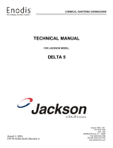
Machine Dimensions:
Height 72.5"
Width 48"
Depth 30.625"
Wall Clearance: 5'
Height 19.75"
Width 21"
Shipping Weight: 750lbs.
Shipping Size:
Length 77"
Depth 41"
Height 89"
124.06
48.07
25.50
9.00
ELECTRICAL
CONNECTION
25.50
9.00
ELECTRICAL
CONNECTION
48.07
102.07
124.06
48.07
25.50
9.00
ELECTRICAL
CONNECTION
25.50
9.00
ELECTRICAL
CONNECTION
48.07
102.07
WITH 44" DISHMACHINE
WITH 66" DISHMACHINE
SPECIFICATIONS
BLOWER/DRYER OPTION DIMENSIONS

8
07610-003-78-18-N
Machine Dimensions:
Height 72.5"
Width 48"
Depth 30.625"
Wall Clearance: 5'
Height 19.75"
Width 21"
Shipping Weight: 750lbs.
Shipping Size:
Length 77"
Depth 41"
Height 89"
Model Designation: 44" 66" 44" STEAM 66" STEAM
Operating Capacity:
Racks per Hour 218 218 218 218
Dishes per Hour 3488 3488 3488 3488
Glasses per Hour 7848 7848 7848 7848
Tank Capacity (Gallons):
Wash Tank 35.6 35.6 35.6 35.6
Pre-Wash Tank N/A 15.8 N/A 15.8
Electrical Loads (as applicable):
Wash Motor HP 3.0 3.0 3.0 3.0
Drive Motor HP 0.25 0.25 0.25 0.25
Pre-Wash Motor HP N/A 2.0 N/A 2.0
Wash Heater kW 15 or 18 18 N/A N/A
OPERATING PARAMETERS
SPECIFICATIONS
NOTE: Always refer to the machine data plate for specic electrical and water requirements.
The material provided on this page is for reference only and may change without notice.
NOTICE
i

9
07610-003-78-18-N
SPECIFICATIONS
OPERATING PARAMETERS
Model Designation: 44" 66" 44" STEAM 66" STEAM
HOT WATER SANITIZING
Water Temperatures (°F):
Pre-Wash Temperature (recommended) N/A 110-140 N/A 110-140
Minimum Wash Temperature 160 160 160 160
Incoming Rinse Temperature 180 180 180 180
Incoming Water Temperature
12 kW Booster 140 140 N/A N/A
18 kW Booster 110 110 N/A N/A
No Booster 180 180 180 180
CHEMICAL SANITIZING
Water Temperatures (°F):
Pre-Wash Temperature (recommended) N/A 110-140 N/A 110-140
Minimum Wash Temperature 120 120 120 120
Minimum Rinse Temperature 120 120 120 120
Incoming Water Temperature
12 kW Booster 80 80 N/A N/A
18 kW Booster 50 50 N/A N/A
No Booster 120 120 120 120
Other Water Requirements:
Water Flow Pressure (PSI) 15 15 15 15
Flow Rate Minimum (GPM) 1.27 1.18 1.27 1.18
Water Line Size (NPT) 1/2" 1/2" 1/2" 1/2"
Drain Line Size (NPT) 1-1/2" 1-1/2" 1-1/2" 1-1/2"
Steam Requirements:
Steam Line for Wash Tank (NPT) N/A N/A 3/4" 3/4"
Steam Flow Pressure (PSI) N/A N/A 10-20 10-20
Consumption @ 15 PSI (lbs/hr) N/A N/A 60 60
NOTE: Always refer to the machine data plate for specic electrical and water requirements.
The material provided on this page is for reference only and may change without notice.
NOTICE
i

10
07610-003-78-18-N
All electrical ratings provided in this manual are for reference only. Always refer to the machine data plate to get the exact
electrical information for this machine. All electrical work performed on machines should be done in accordance
with applicable local, state, territorial, and national codes. Work should only be performed by qualied electricians and
authorized service agents. A list of authorized Service Agencies is located in the back of this manual.
Note that all electrical wiring used in the dishmachine must be rated, at a minimum, for 212 °F (100 °C), and that only
copper conductors must be used.
Where applicable, heating element amperage draws have been adjusted for the assumed input voltage. The manufacturer
assumes incoming voltages will be either 208, 230, or 460 Volts. Some of the heating elements used in our machines are
actually rated for other voltages, such as 240 or 480 Volts. Always verify the amperage draw of the machine in operation
when sizing circuit protection.
If the machine is equipped with the optional rinse heater, note the rinse heater has its own electrical connection and
therefore requires a separate service. Amperage loads for motors and heaters are called out on the machine data plate
for the installation/service technician.
The electrical congurations of the machines are as follows:
Available Electrical Characteristics:
• 208 V, 60 Hz, Single-phase
• 230 V, 60 Hz, Single-phase
• 208 V, 60 Hz, Three-phase
• 230 V, 60 Hz, Three-phase
• 460 V, 60 Hz, Three-phase
Available Wash Tank Heaters:
• 15 kW (standard for CREW 44)
• 18 kW (optional for CREW 44, standard for CREW 66)
Available Electrical Characteristics:
• None (standard)
• 12 kW (40 °F rise in temperature)
• 18 kW (70 °F rise in temperature)
ELECTRICAL REQUIREMENTS
SPECIFICATIONS
i

11
07610-003-78-18-N
Volts Phase Freq
Wash
Motor
Amps
Drive
Motor
Amps
Wash
Heater
Amps
Total
Load
208 1 60 10.0 1.8 72.1 83.9
230 1 60 10.0 1.8 *59.9 71.7
240 1 60 10.0 1.8 62.5 74.3
208 3 60 8.6 1.1 41.6 51.3
230 3 60 8.4 1.1 *34.6 44.1
240 3 60 8.4 1.1 36.1 45.6
460 3 60 4.2 0.6 **17.3 22.1
480 3 60 4.2 0.6 18.1 22.9
44" with 15 kW Wash Heater
Volts Phase Freq
Wash
Motor
Amps
Drive
Motor
Amps
Wash
Heater
Amps
Total
Load
208 1 60 10.0 1.8 86.5 98.3
230 1 60 10.0 1.8 *71.9 83.7
240 1 60 10.0 1.8 75.0 86.8
208 3 60 8.6 1.1 50.0 59.7
230 3 60 8.4 1.1 *41.5 51.0
240 3 60 8.4 1.1 43.4 52.9
460 3 60 4.2 0.6 **20.8 25.6
480 3 60 4.2 0.6 21.7 26.5
44" with 18 kW Wash Heater
Volts Phase Freq
Wash
Motor
Amps
Drive
Motor
Amps
Total
Load
208 1 60 10.0 1.8 11.8
230 1 60 10.0 1.8 11.8
208 3 60 8.6 1.1 9.7
230 3 60 8.4 1.1 9.5
460 3 60 4.2 0.6 4.8
44" Steam
* Denotes 240 volt heating elements that have been down-rated when 230 volts is applied.
** Denotes 480 volt heating elements that have been down-rated when 460 volts is applied.
SPECIFICATIONS
ELECTRICAL REQUIREMENTS
i
/