Page is loading ...

AX8000 | Multi-axis
servo system
Operating instructions | EN
11/21/2019 | Version 1.0
Order No.: TDmlAX-8000-0000-0201


Table of content
Version: 1.0 ─── 3AX8000
Table of content
Documentation notes .......................................................................................................................................... 5
Disclaimer ......................................................................................................................................................... 5
Version numbers............................................................................................................................................... 7
Scope of the documentation ............................................................................................................................. 7
Staff qualification............................................................................................................................................... 8
Safety and instruction ....................................................................................................................................... 9
Explanation of symbols ..................................................................................................................................... 9
Beckhoff Services ........................................................................................................................................... 10
For your safety................................................................................................................................................... 11
Safety pictograms ........................................................................................................................................... 11
General safety instructions ............................................................................................................................. 12
Product overview............................................................................................................................................... 14
Power supply module...................................................................................................................................... 15
Axis module .................................................................................................................................................... 16
Capacitor module............................................................................................................................................ 17
Product characteristics.................................................................................................................................... 18
Ordering options ............................................................................................................................................. 19
Intended use ................................................................................................................................................... 20
Dual Use ......................................................................................................................................................... 21
Technical data.................................................................................................................................................... 22
Data for operation and environment ............................................................................................................... 22
Power supply modules.................................................................................................................................... 23
Axis modules................................................................................................................................................... 24
Capacitor module............................................................................................................................................ 25
Brake resistor [+]............................................................................................................................................. 25
Dimensional drawings..................................................................................................................................... 26
Scope of supply ................................................................................................................................................. 29
Packaging ....................................................................................................................................................... 30
Transport and storage....................................................................................................................................... 31
Conditions ....................................................................................................................................................... 31
Transport......................................................................................................................................................... 32
Long-term storage........................................................................................................................................... 32
Technical description........................................................................................................................................ 33
Installation position ......................................................................................................................................... 33
Residual current circuit breaker ...................................................................................................................... 33
Safe system stop ........................................................................................................................................... 33
Wide voltage range ......................................................................................................................................... 34
Dimensioning .................................................................................................................................................. 35
Display ............................................................................................................................................................ 38
Capacitor module............................................................................................................................................ 42
Mechanical Installation ..................................................................................................................................... 43
Preparation ..................................................................................................................................................... 43
Modules .......................................................................................................................................................... 45
Electrical installation......................................................................................................................................... 48
Project planning .............................................................................................................................................. 48
Block diagrams ............................................................................................................................................... 50
Grounding ....................................................................................................................................................... 54
Power supply .................................................................................................................................................. 58
Voltage input ................................................................................................................................................... 59

Table of content
4 ─── Version: 1.0AX8000
Brake chopper................................................................................................................................................. 60
DC link ............................................................................................................................................................ 61
Fieldbus system .............................................................................................................................................. 62
Multi-feedback................................................................................................................................................. 63
Motor feedback ............................................................................................................................................... 65
Digital inputs ................................................................................................................................................... 66
Supply networks.............................................................................................................................................. 67
Fuse protection ............................................................................................................................................... 68
Commissioning.................................................................................................................................................. 71
Before commissioning..................................................................................................................................... 71
During commissioning..................................................................................................................................... 71
Prerequisites during operation ........................................................................................................................ 72
After operation ................................................................................................................................................ 72
Maintenance and cleaning ................................................................................................................................ 73
Intervals .......................................................................................................................................................... 73
Accessories........................................................................................................................................................ 74
Brake resistor.................................................................................................................................................. 74
Decommissioning.............................................................................................................................................. 75
Disassembly.................................................................................................................................................... 75
Disposal .......................................................................................................................................................... 76
Guidelines and Standards ................................................................................................................................ 77
Standards........................................................................................................................................................ 77
Guidelines ....................................................................................................................................................... 78
Test centers .................................................................................................................................................... 79
EU conformity ................................................................................................................................................. 79
UL certification ................................................................................................................................................ 80
Index ................................................................................................................................................................... 82

Documentation notes
Version: 1.0 ─── 5AX8000
Documentation notes
Disclaimer
The documentation has been prepared with care. Beckhoff products
are subject to continuous further development.
We reserve the right to revise the documentation at any time and
without notice.
No claims for the modification of products that have already been
supplied may be made on the basis of the data, diagrams and de-
scriptions in this documentation.
Trademarks
Beckhoff
®
, TwinCAT
®
, EtherCAT
®
, EtherCAT G
®
, EtherCAT G10
®
,
EtherCAT P
®
, Safety over EtherCAT
®
, TwinSAFE
®
, XFC
®
, XTS
®
and
XPlanar
®
are registered and licensed trademarks of Beckhoff Auto-
mation GmbH.
The use of other brand names or designations by third parties may
lead to an infringement of the rights of the owners of the corre-
sponding designations.
Patents
The EtherCAT technology is protected by patent rights through the
following registrations and patents with corresponding applications
and registrations in various other countries:
• EP1590927
• EP1789857
• EP1456722
• EP2137893
• DE102015105702
EtherCAT
®
is a registered trademark and patented technology, li-
censed by Beckhoff Automation GmbH & Co. KG, Germany.

Documentation notes
6 ─── Version: 1.0AX8000
Limitation of liability
All components of this product described in the original operating in-
structions are delivered in a hardware and software configuration,
depending on the application requirements. Modifications and
changes to the hardware and/or software configuration that go be-
yond the documented options are prohibited and nullify the liability
of Beckhoff Automation GmbH & Co. KG.
In addition, the following are excluded from the liability:
• Failure to comply with this documentation
• Improper use
• Use of untrained personnel
• Use of unauthorized spare parts
Copyright
© Beckhoff Automation GmbH & Co. KG, Germany
The copying, distribution and utilization of this document as well as
the communication of its contents to others without express autho-
rization is prohibited.
Offenders will be held liable for the payment of damages. We re-
serve all rights in the event of registration of patents, utility models
and designs.

Documentation notes
Version: 1.0 ─── 7AX8000
Version numbers
Origin of the document
These operating instructions were originally written in German. All
other languages are derived from the German original.
Product features
The product features specified in the latest version of the original
operating instructions are always applicable. Further information
given on the product pages of the Beckhoff homepage, in emails or
in other publications is not authoritative.
Issue Comment
1.0 First release
Scope of the documen-
tation
The complete documentation consists of the following documents:
AX8000 Definition
Translation of the original instructions;
this documentation
Description of the mechanical and electri-
cal parameters as well as all information
necessary for the use, installation and
mounting of the AX8000 multi-axis servo
system
Commissioning under TwinCAT3 Commissioning tutorial under TwinCAT3
including user information on the
TCDriveManager 2 and a description of
the safety function STO; Safe Torque Off
over FSoE; Safety over EtherCAT
CoE object description Documentation of the CAN over Ether-
CAT objects with attribute tables
Diagnostic messages Documentation of the error messages of
the AX8000 multi-axis servo system with
attribute tables, problem descriptions and
possible solutions
AX2090-BW80-xxxx brake resistors Operating instructions for the use and in-
stallation of the AX2090-BW80 brake re-
sistors as accessories for the AX8000
multi-axis servo system

Documentation notes
8 ─── Version: 1.0AX8000
Staff qualification
These operating instructions are intended for trained control and au-
tomation specialists with knowledge of the applicable and required
standards and directives.
Qualified personnel must have knowledge of drive technology and
electrical equipment as well as knowledge of safe working on electri-
cal systems and machines. This includes knowledge of proper setup
and preparation of the workplace as well as securing the working
environment for other persons.
The documentation published at the time must be used for each in-
stallation and commissioning. The products must be used in compli-
ance with all safety requirements, including all applicable laws, regu-
lations, provisions and standards.
Designation of the target groups Explanation
Instructed person This target group has been informed about the possible dangers of improper use.
The assigned scope of duties is clearly defined. Training will be provided for any
tasks outside this scope. Instructions on the required protective measures and de-
vices were provided.
Trained user This target group meets all the requirements of an instructed person. In addition,
machine-specific or plant-specific training has taken place at the machine manufac-
turer or vendor.
Trained specialists Users who, based on their training, knowledge and experience, are able to assess
the tasks assigned to them and recognize potential hazards, are regarded as
trained specialists. Work experience over several years in a relevant field can also
be considered as part of the technical training.
Qualified electricians Qualified electricians are able to work on electrical machines or systems based on
their specialist training like university degree, apprenticeship or specialist training.
Possible sources of danger are automatically identified and avoided.
Qualified electricians are specially trained for the working environment and are fa-
miliar with the relevant standards and guidelines. Knowledge of control engineering
and automation is required. The provisions of the accident prevention regulations
must be complied with.
Customer service Customer service is provided by technicians who have been demonstrably trained
and authorized by Beckhoff or the machine manufacturer to work on the respective
machine or plant.

Documentation notes
Version: 1.0 ─── 9AX8000
Safety and instruction
Read the contents that refer to the activities you have to perform
with the product. Always read the chapter "For your safety", [Page
11] in the operating instructions. Observe the warning notes in the
chapters so that you can handle and work properly and safely with
the product.
Explanation of symbols
Various symbols are used for a clear arrangement:
► The triangle indicates instructions that you should execute
• The bullet point indicates an enumeration
[…] The square parentheses indicate cross-references to other
text passages in the document
[+] The plus sign in square brackets indicates ordering options
and accessories
Pictograms
Pictograms are used to identify important text passages:
The warning triangle indicates warning notes.
The possible consequences of failure to observe these include:
• Damage and/or serious injuries
• Fatal injuries
The warnings are shown at the points in the documentation where
it is important to observe them in order to prevent accidents and
injuries.
Notes are used for important information on the product.
The possible consequences of failure to observe these include:
• Malfunctions of the product
• Damage to the product
• Damage to the environment
Information
This sign indicates information, tips and notes for dealing with the
product or the software.
Example
This symbol shows examples of how to use the product or soft-
ware.

Documentation notes
10 ─── Version: 1.0AX8000
Beckhoff Services
Beckhoff and its international partner companies offer comprehen-
sive support and service.
Support
The Beckhoff Support offers technical advice on the use of individ-
ual Beckhoff products and system planning. Staff provide assistance
for programming and commissioning complex automation systems
and offer a comprehensive training program.
Hotline: +49(0)5246/963-157
Fax: +49(0)5246/963-199
E-mail: [email protected]
Web: www.beckhoff.de/support
Training
Training in Germany takes place in our training center at the Beck-
hoff headquarters in Verl, at branch offices or, by arrangement, at
the customer's premises.
Hotline: +49(0)5246/963-5000
Fax: +49(0)5246/963-95000
E-mail: [email protected]
Web: www.beckhoff.de/training
Service
The Beckhoff Service Center supports you with after-sales services
such as on-site service, repair service or spare parts service.
Hotline: +49(0)5246/963-460
Fax: +49(0)5246/963-479
E-mail: [email protected]
Web: www.beckhoff.de/service
Download area
In the download area you will find product information, software up-
dates, the TwinCAT automation suite, documentation and much
more.
Web: www.beckhoff.de/download
Headquarters
Beckhoff Automation GmbH & Co. KG
Hülshorstweg 20
33415 Verl
Germany
Phone: +49(0)5246/963-0
Fax: +49(0)5246/963-198
E-mail: [email protected]
Web: www.beckhoff.de
The addresses of the international Beckhoff branch offices can be
found on the Beckhoff website: http://www.beckhoff.de

For your safety
Version: 1.0 ─── 11AX8000
For your safety
Read this chapter containing general safety information. The chap-
ters in these operating instructions also contain warning notices. Al-
ways observe the safety instructions for your own safety, the safety
of other persons and the safety of the product.
When working with control and automation products, many dangers
can result from careless or incorrect use. Work particularly thor-
oughly, not under time pressure and responsibly towards other peo-
ple.
Safety pictograms
On Beckhoff products you will find attached or lasered safety pic-
tograms, which vary depending on the product. They serve to pro-
tect people and to prevent damage to the products. Safety pic-
tograms must not be removed and must be legible for the user.
Warning of high voltage!
The DC link capacitors and test contacts on all modules can carry
life-threatening voltages of over 875V
DC
.

For your safety
12 ─── Version: 1.0AX8000
General safety instruc-
tions
This chapter provides you with instructions on security when han-
dling the AX8000 multi-axis servo system. Servo drives cannot be
used alone and are therefore regarded as incomplete machines.
They must be installed in a machine / plant by the machine manu-
facturer. The documentation prepared by the machine manufacturer
is to be read afterwards.
Before operation
Keep the surroundings clean
Keep your workplace and the surrounding area clean. Ensure safe
working. Prevent dirt from penetrating into the components.
Secure the control cabinet
When working on machines, secure the control cabinet against inad-
vertent power-up.
Do not use defective servo drives
Observe the specifications in the "technical data", [Page22] during
storage, transport and operation. Do not use damaged servo drives.
Check safety pictograms
Check whether the designated pictograms are on the product. Re-
place missing or illegible stickers.
Observe tightening torques
Install connections and components in compliance with the specified
tightening torques and check them regularly.
Ground electrical components or modules correctly
Do not touch electrical components or modules unless you are
wearing protective ESD clothing. Only walk on conductive floors.
Only use original packaging for further processing
When shipping, transporting, storing and packing, use the original
packaging or conductive materials. Conductive materials are foam
or aluminum, for example.

For your safety
Version: 1.0 ─── 13AX8000
During operation
Avoid contact with DC link DC+ and DC-
Measure the voltage on the DC link test contacts DC+ und DC-. Ob-
serve the following delay times after disconnecting from the mains
supply:
• AX8620 and AX8640 30 minutes
• AX8108, AX8118 and AX8206 30 minutes
Do not work on live electrical parts
Do not open the AX8000 when it is live. Ensure that the protective
conductor is properly connected. Never disconnect electrical con-
nections while they are live. Only work on the AX8000 when the
voltage has dropped to < 50V. Disconnect all components from the
mains and secure against reconnection.
Do not touch hot surfaces
Check cooling of the surfaces with a thermometer. Do not touch the
housing during and after operation. Leave the servo drive to cool
down for at least 15minutes after it is switched off.
Avoid overheating
Operate the servo drive according to the technically foreseen speci-
fications. Please refer to chapter: "Technical data", [Page22]. Pro-
vide for adequate cooling and switch the servo drive off immediately
if the temperature is too high.
Do not touch rotating components
Do not touch any rotating components during the operation of a
plant with the servo drive. Ensure that all parts / components on the
machine / plant are firmly seated.
After operation
De-energize and switch off components before working on
them
Carry out a voltage test and check all safety-relevant devices for
functionality. Secure the working environment and the control cabi-
net against inadvertent power-up. Observe the chapter "Decommis-
sioning", [Page75].

Product overview
14 ─── Version: 1.0AX8000
3
Product overview
Number Explanation
1 Housing
2 Display; with 2-channel modules: left channel 1, right channel 2
3 Digital inputs X15, channel A and X25, channel B
4 Feedback connection X21 and X22; optional
5 Quick coupling 24V
DC
; AX bridge
6 EtherCAT connection
7 Quick coupling, DC link and protective earth PE; AX bridge
8 8-pin motor connector X23, channel B; U, V, W, PE, T+ / OCT+, T- / OCT-, B+ and B-
9 8-pin motor connector X13, channel A; U, V, W, PE, T+ / OCT+, T- / OCT-, B+ and B-
10 AX-Bridge: DC link, FE
11 AX-Bridge: 24V
DC
12 Fieldbus EtherCAT input X04
13 Fieldbus EtherCAT output X05
14 10-pin input terminal X01; DC, 24V, supply network, PE and external brake resistor
15 Earthing bolt
16 Test contact DC link DC-
17 Test contact DC link DC+
18 Test contact GND
19 Test contact +24V
DC

Product overview
Version: 1.0 ─── 15AX8000
Power supply module
3.1.1
Name plate
Number Explanation
1 Order number
2 Serial number
3 Rated input voltage
4 Rated input current
5 Input frequency
6 Maximum ambient temperature
7 Rated output voltage
8 Rated output current
9 Date of manufacture
10 QR code
11 EtherCAT conformity
12 cULus approval
13 EAC conformity
14 CE approval
3.1.2
Type key
AX 8x yz-a b c d-0000 Explanation
AX Product line
Servo drive
8 Series
AX8000
x Supply
6
In combination with "a"
yz Rated output current
20 = 7A
DC
- single-phase supply
20 = 20A
DC
- three-phase supply
40 = 40A
DC
- three-phase supply
a Supply
0 = three-phase 200 to 480V
AC
1 = single-phase or three-phase 100 to 240V
AC
b Reserved
0 = Standard
c Hardware features
0 = Standard
d Execution
0 = Standard

Product overview
16 ─── Version: 1.0AX8000
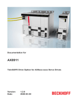
Axis module
3.2.1
Name plate
9 10
12
11
13
1
2
3
4
5
6
8
7
Input rated voltage : 680 V ( )DC UL
: 875 V ( -Link max.)DC DC
Max. amb. temp. : 55 °C
Catalog No. : 8206-0000-0000 AX
Serial # : 000000100
Output rated voltage : 3 0V - mains voltage PH AC
Output rated current : 2 x 6 A
Output frequency range : 0 - 599 Hz
Manufacturing date : 2017 / 02
Made in Germany
Ind. Cond. E.q.
41GE
BECKHOFF
Phone: + 49 52 46 / 9 63 - 0
Fax. : + 49 52 46 / 9 63 - 198
www.beckhoff.com [email protected]
Huelshorstweg 20
D-33415 Verl
Germany
Automation GmbH & Co. KG
Number Explanation
1 Order number
2 Serial number
3 Rated input voltage
4 Maximum ambient temperature
5 Rated output voltage
6 Rated output current
7 Output frequency range
8 Date of manufacture
9 QR code
10 EtherCAT conformity
11 cULus approval
12 EAC approval
13 CE conformity
3.2.2
Type key
AX 8x yz-a b c d-0000 Explanation
AX Product line
Servo drive
8 Series
AX8000
x Axis module
1 = single-channel servo axis
2 = two-channel servo axis
yz Rated channel current
08 = 1 x 8A
18 = 1 x 18A
06 = 2 x 6A
a DC link voltage
0 = 0 to 875V
DC
b Safety function
0 = No safety function
1 = Safety functions, see "Ordering options", [Page19]
2 = Safety functions, see "Ordering options", [Page19]
c Hardware features
0 = OCT
1 = EnDat 2.2, BiSS C; Multi-Feedback Interface
d Execution
0 = Standard

Product overview
Version: 1.0 ─── 17AX8000
Capacitor module
3.3.1
Name plate
Number Explanation
1 Order number
2 Serial number
3 Rated input voltage
4 Maximum ambient temperature
5 DC link capacitance
6 Date of manufacture
7 QR code
8 EtherCAT conformity
9 cULus approval
10 CE conformity
3.3.2
Type key
AX 8 8 yz-a b c d-0000 Explanation
AX Product line
Servo drive
8 Series
AX8000
8 Option module
yz Option modules
10 = capacitor module
a Supply
0 = 0 to 875V
DC
b Reserved
0 = Standard
c Hardware features
0 = Standard
d Execution
0 = Standard

Product overview
18 ─── Version: 1.0AX8000
Product characteristics
Short cycle times
With the servo drive you can implement fast and highly dynamic po-
sitioning tasks through the integrated control technology. EtherCAT
enables the ideal connection to the PC-based control technology.
With EtherCAT and the AX8000 multi-axis servo system you can
achieve minimum cycle times, synchronicity and simultaneity in the
drive technology.
Scalable rated motor power
With the axis modules you can operate different rated motor powers
through scalable motor current measurement. A rated motor current
of between 1A and 8A can be set on an 8A module without influ-
encing the quality of the resolution.
Operation of different motor sizes
With a two-channel axis module you can connect two identical motor
sizes or also different ones. The sum of the rated currents of both
servo motors is relevant for the selection of the axis module. The
sum of the rated currents of the axis modules is the most that can
be provided at the same time here.
High-speed capture inputs
The digital high-speed capture inputs record binary control signals
from the process level and make them available for latching / captur-
ing an encoder position. The signal propagation delay of these in-
puts is 15µs.
Diagnostics and parameter display
The display of the AX8000 multi-axis servo system shows error
groups in various categories and is based on the 7-segment tech-
nology. The output takes place as LED.
Toolless connection
The simple and fast connection of the DC link of power supply mod-
ules and several axis modules is enabled by the AX bridge. The
connection takes place without tools with spring-loaded terminals for
DC link, control circuit and EtherCAT. The compact design of the
AX8000 multi-axis servo system enables simple mounting inside the
control cabinet.

Product overview
Version: 1.0 ─── 19AX8000
Ordering options
Ordering options are defined via the type key and must be ordered
separately. The listed components cannot be retrofitted.
Drive-integrated safety
technology
The axis modules are optionally available with integrated safety
functions . These conform to IEC 61800-5-2 and fulfill the following
safety standards:
• EN ISO 13849-1:2015, up to Cat 4, PL e
• EN 61508:2010, SIL 3
• EN 62061:2005 + A1:2013/A2:2015 SILCL3
Communication takes place via the Safety-over-EtherCAT FSoE
protocol according to IEC 61784-3-12. The safety function STO can
optionally be activated via two safely integrated digital inputs or
FSoE.
Order designation Safety functions
AX8xxx-x1xx STO; safe torque off
SS1; safe stop 1
SBC; safe brake control
AX8xxx-x2xx STO; safe torque off
SOS; safe operating stop
SS1; safe stop 1
SS2; safe stop 2
SLP; safely-limited position
SCA; safe cam
SLI; safely-limited increment
SDIp; safe direction positive
SDIn; safe direction negative
SLS; safely-limited speed
SSR; safe speed range
SSM; safe speed monitor
SMS; safe maximum speed
SMA; safe maximum acceleration
SAR; safe acceleration range
SBC; safe brake control
SBT; safe break test
Observe the TwinSAFE documentation
Before putting the axis module with integrated safety technology
into operation, read the documentation:
• "AX8911 TwinSAFE Drive Option for servo drives from the
AX8000 series"
Multi-feedback interface
The "multi-feedback interface", [Page63] supports the digital feed-
back systems EnDat 2.2 or BiSS-C.
There are two further D-Sub 15-pin connectors behind the front
cover of the axis module. Therefore, up to two EnDat 2.2 or BiSS-C
feedbacks can be connected with a single-axis module. With a dual-
axis module one feedback interface is assigned to each axis.

Product overview
20 ─── Version: 1.0AX8000
Intended use
The AX8000 multi-axis servo system may be operated exclusively
for the activities foreseen and defined in this documentation, taking
into account the prescribed environmental conditions.
The components are to be installed only in closed control cabinets in
electrical plants or machines and put into operation only as inte-
grated components of the plant or machine.
Read the entire drive system documentation:
• This translation of the original instructions
• Complete machine documentation provided by the machine
manufacturer
Improper use
Any use exceeding the permissible values specified in the Technical
data is considered improper and therefore prohibited.
The AX8000 multi-axis servo system is not suitable for use in the
following areas:
• ATEX zones without suitable housing
• Areas with aggressive environments, for example aggressive
gases or chemicals
The relevant standards and directives for EMC interference emis-
sions must be complied with in residential areas.
/