Page is loading ...

User information
Multi axis servo system - AX8000
Diagnostic messages
1.1
2019-02-28
Version:
Date:


Inhaltsverzeichnis
Multi axis servo system - AX8000 3
Version: 1.1
Inhaltsverzeichnis
1 Notes on the documentation ....................................................................................................................9
2 Introduction to the diagnostic system...................................................................................................10
2.1 Basic knowledge of the diagnostic system ......................................................................................10
2.2 Settings with respect to the diagnostic system................................................................................14
3 Standard-Messages.................................................................................................................................15
3.1 0000, No Error .................................................................................................................................15
3.2 5190, Test 5V supply failed .............................................................................................................16
3.3 5580, Read failure EEPROM...........................................................................................................17
3.4 5581, Checksum failure EEPROM ..................................................................................................18
3.5 5582, EEPROM contains blank Data ..............................................................................................19
3.6 5583, Unexpected EEPROM...........................................................................................................20
3.7 5584, EEPROM contains blank Data ..............................................................................................21
3.8 5585, Unexpected EEPROM...........................................................................................................22
3.9 5586, Restored Errormessages from persistent memory................................................................23
3.10 5590, Detected incompatible Pcb....................................................................................................24
3.11 5591, Identity incompatible to a Pcb................................................................................................25
3.12 5592, FirmwareIndex is incompatible to this Firmware ...................................................................26
3.13 5593, Structure Version is incompatible to this Firmware ...............................................................27
3.14 5594, Simulating persistent data features. ......................................................................................28
3.15 5596, Storing of persistent data failed. ............................................................................................29
3.16 5597, Unsupported prototype hardware. .........................................................................................30
3.17 5598, Identity incompatible to Device..............................................................................................31
3.18 5599, Identity incompatible to a Device...........................................................................................32
3.19 6180, Internal Software Error Type A ..............................................................................................33
3.20 6181, Internal Software Error Type B ..............................................................................................34
3.21 6182, Internal Software Error Type C..............................................................................................35
3.22 6190, Init Timeout............................................................................................................................36
3.23 6382, Illegal Slotconfiguration. Slot is empty...................................................................................37
3.24 6383, Illegal Slotconfiguration. Double Feedback Selection. ..........................................................38
3.25 6384, Illegal Slotconfiguration. Slot has to be empty.......................................................................39
3.26 63B0, Transition Pre-Op to Safe-Op (ECat) not successful ............................................................40
3.27 63B1, Transition Safe-Op to Op (ECat) not successful ...................................................................41
3.28 63B2, Transition Op to Safe-Op (ECat) not successful ...................................................................42
3.29 63B3, Transition Safe-Op to Pre-Op (ECat) not successful ............................................................43
3.30 8180, System restart or sync lost ....................................................................................................44
3.31 8181, Lost Distributed clocks Sync..................................................................................................45
3.32 A000, Transition Pre-Op to Safe-Op not successful. Sync Manager Length Error. ........................46
3.33 A001, Transition Pre-Op to Safe-Op not successful. Sync Manager Address Error. ......................47
3.34 A002, Transition Pre-Op to Safe-Op not successful. Sync Manager Settings Error. ......................48
3.35 A003, Transition Pre-Op to Safe-Op not successful. Sync Manager Address Range overlap........49
3.36 A004, Sync Manager is disabled and has a Size unequal zero. .....................................................50
3.37 A005, Sync Manager Address is not multiple of 4...........................................................................51
3.38 A00B, Dynamic Sync Manager Address is not multiple of 4. ..........................................................52
3.39 A00C, Dynamic Sync Manager Address Range overlap.................................................................53

Inhaltsverzeichnis
Multi axis servo system - AX80004
Version: 1.1
3.40 A00D, Dynamic Sync Manager Settings Error. ...............................................................................54
3.41 A00E, Dynamic Sync Manager Address Error. ...............................................................................55
3.42 A00F, Dynamic Sync Manager Length Error...................................................................................56
3.43 A010, SDO Complete Access Error. ...............................................................................................57
3.44 A011, Pdo Mapping Error: Unable to map Object (not possible).....................................................58
3.45 A013, Pdo Mapping Error: Double Mapping of Object. ...................................................................59
3.46 A015, Pdo Mapping Error: Unable to map Object (no Mappings left). ............................................60
3.47 A017, Pdo Mapping Error: Object has to be mapped always..........................................................61
3.48 A019, Pdo Mapping Error: Object has to be mapped because of modes of operation. ..................62
3.49 A01B, Pdo BitMapping Error: Object A is not next to Object B. ......................................................63
3.50 A01D, Pdo BitMapping Error: Can not Transform Bit-Mappings to Byte-Mappings. .......................64
3.51 A01F, Pdo Mapping Error: Invalid Oversampling Factor. ................................................................65
3.52 A021, Pdo Mapping Error: Oversampling is not allowed. ................................................................66
3.53 A023, Pdo Assignment Error ...........................................................................................................67
3.54 A031, DynPdo Mapping Warning: Unable to map Object (not possible).........................................68
3.55 A033, DynPdo Mapping Warning: Double Mapping of Object.........................................................69
3.56 A035, DynPdo Mapping Warning: Unable to map Object (no Mappings left)..................................70
3.57 A037, DynPdo Mapping Warning: Object has to be mapped always. .............................................71
3.58 A039, DynPdo Mapping Warning: Object has to be mapped because of modes of operation........72
3.59 A03B, DynPdo BitMapping Warning: Object A is not next to Object B............................................73
3.60 A03D, DynPdo BitMapping Warning: Can not Transform Bit-Mappings to Byte-Mappings. ...........74
3.61 A03F, DynPdo Mapping Warning: Invalid Oversampling Factor. ....................................................75
3.62 A041, DynPdo Mapping Warning: Oversampling is not allowed. ....................................................76
3.63 A043, DynPdo Assignment Warning ...............................................................................................77
3.64 A080, Safe-Op is not possible because the local TwinCAT Runtime is in ConfigMode. .................78
3.65 A081, Transition Pre-Op to Safe-Op not successful. Safetycard not detected................................79
3.66 A082, EtherCAT Slave Stack Error: ................................................................................................80
3.67 FFFD, Debug firmware, replace "As soon as possible"!..................................................................81
3.68 FFFF, Internal Error, Additional Errorcode ......................................................................................82
4 Diagmessages of module DeviceMain ..................................................................................................83
4.1 3210, DC link overvoltage ...............................................................................................................83
4.2 4380, Fan speed seems to be zero. ................................................................................................84
4.3 5112, Supply undervoltage: supply +24V ........................................................................................85
4.4 5181, Power supply controlword, torque off order...........................................................................86
4.5 5182, Power supply controlword, live counter inactive....................................................................87
4.6 5183, Power supply controlword, NC handling order ......................................................................88
4.7 5185, Power supply controlword, non-regenerative brake order.....................................................89
4.8 5186, Power supply controlword, regenerative brake order ............................................................90
4.9 5192, Supply overvoltage: supply +24V ..........................................................................................91
4.10 6320, Parameter error .....................................................................................................................92
4.11 8780, Configured Sync1 Cycle Time is above Maximum ................................................................93
4.12 8781, Configured Sync1 Cycle Time is below Minimum .................................................................94
4.13 8782, Configured Sync1 Cycle Time is not a multiple of the Sync0 Cycle Time .............................95
4.14 8783, Configured Sync0 Cycle Time is not legal.............................................................................96
4.15 A017, Pdo Mapping Error: Object has to be mapped always..........................................................97
4.16 FFFF, Internal Error, Additional Errorcode ......................................................................................98

Inhaltsverzeichnis
Multi axis servo system - AX8000 5
Version: 1.1
5 Diagmessages of module DeviceDebug ...............................................................................................99
5.1 FFFF, Internal Error, Additional Errorcode ......................................................................................99
6 Diagmessages of module AxisMain ....................................................................................................100
6.1 0000, No Error ...............................................................................................................................100
6.2 2340, Short circuit (motor-side) .....................................................................................................101
6.3 2380, Continuous over current (device output side) Phase U .......................................................102
6.4 2381, Continuous over current (device output side) Phase V .......................................................103
6.5 2382, Continuous over current (device output side) Phase W ......................................................104
6.6 2383, Phase U current offset out of range.....................................................................................105
6.7 2384, Phase V current offset out of range.....................................................................................106
6.8 2385, Phase W current offset out of range....................................................................................107
6.9 3180, Phase failure motor .............................................................................................................108
6.10 3220, DC link under-voltage ..........................................................................................................109
6.11 3280, DC link is not ready .............................................................................................................110
6.12 4310, Drive overtemperature shut down .......................................................................................111
6.13 5180, Output stage STO active. ....................................................................................................112
6.14 5184, Supply DC link circuit is not ready .......................................................................................113
6.15 5187, Power supply communication is not established .................................................................114
6.16 5441, Positive limit switch active ...................................................................................................115
6.17 5442, Negative limit switch active..................................................................................................116
6.18 5443, Loss of the hardware enable ...............................................................................................117
6.19 5444, Loss of the hardware enable (Reaction TorqueOff) ............................................................118
6.20 5595, Modulo remainder will not be stored....................................................................................119
6.21 6183, Internal Watchdog Error ......................................................................................................120
6.22 638A, The Axis seems not to be parameterized............................................................................121
6.23 6390, Factor Group Parameters: Feed constant illegal feed.........................................................122
6.24 6391, Factor Group Parameters: Feed constant illegal shaft revolutions......................................123
6.25 6392, Factor Group Parameters: Gear ratio illegal Motor shaft revolutions ..................................124
6.26 6393, Factor Group Parameters: Gear ratio illegal Driving shaft revolutions ................................125
6.27 6394, Factor Group Parameters: Position encoder resolution illegal encoder increments............126
6.28 6395, Factor Group Parameters: Position encoder resolution illegal motor revolutions................127
6.29 6396, additional Factor Group Parameters: Feed constant illegal feed ........................................128
6.30 6397, additional Factor Group Parameters: Feed constant illegal shaft revolutions .....................129
6.31 6398, additional Factor Group Parameters: Gear ratio illegal Motor shaft revolutions..................130
6.32 6399, additional Factor Group Parameters: Gear ratio illegal Driving shaft revolutions................131
6.33 639A, additional Factor Group Parameters: Position encoder resolution illegal encoder increments
.......................................................................................................................................................132
6.34 639B, additional Factor Group Parameters: Position encoder resolution illegal motor revolutions
.......................................................................................................................................................133
6.35 639C, Velocity factor illegal. ..........................................................................................................134
6.36 639D, Acceleration factor illegal. ...................................................................................................135
6.37 639E, Scaling index object does not fit the Factor group parameters for the first Encoder...........136
6.38 639F, Scaling index object does not fit the Factor group parameters for the second Encoder .....137
6.39 63A0, Motor or Primary Feedback changed..................................................................................138
6.40 63A1, Secondary Feedback changed ...........................................................................................139
6.41 63A2, Offset position actual value: No position offset existing in source 'encoder memory' .........140

Inhaltsverzeichnis
Multi axis servo system - AX80006
Version: 1.1
6.42 63A3, Offset additional position actual value: No position offset existing in source 'encoder
memory' .........................................................................................................................................141
6.43 63A4, Offset position actual value: No position offset existing in source 'drive memory' ..............142
6.44 63A5, Offset additional position actual value: No position offset existing in source 'drive
memory' .........................................................................................................................................143
6.45 63A6, Jerk factor illegal. ................................................................................................................144
6.46 63A7, The range of the Position range limit is below the minimum accepted value......................145
6.47 63A8, Position range limit Inc with remainder is not supported for primary feedback. ..................146
6.48 63A9, Position range limit Inc with remainder is not supported for secondary feedback. .............147
6.49 63AA, Object changed in EtherCAT SafeOP or OP. .....................................................................148
6.50 7180, Motor brake: Current monitoring error. ................................................................................149
6.51 7380, Current sensor motor phase U ............................................................................................150
6.52 7381, Current sensor motor phase V ............................................................................................151
6.53 7382, Current sensor motor phase W ...........................................................................................152
6.54 8182, EtherCAT Statemachine shutdown with enabled Axis ........................................................153
6.55 8183, Controlword output cycle counter monitoring ......................................................................154
6.56 8184, Dynoutput cycle counter monitoring ....................................................................................155
6.57 8185, Axis needs an extended fault reset command.....................................................................156
6.58 8A80, Illegal Modes Of Operation .................................................................................................157
6.59 8A81, Illegal Modes Of Operation change.....................................................................................158
6.60 A017, Pdo Mapping Error: Object has to be mapped always........................................................159
6.61 FF01, Init Timeout .........................................................................................................................160
6.62 FF07, Error reaction forced: Torque Off ........................................................................................161
6.63 FF08, Error reaction forced: Shorted Coils Brake .........................................................................162
6.64 FF09, Error reaction forced: Open Loop Ramp .............................................................................163
6.65 FF0A, Error reaction forced: Closed Loop Ramp ..........................................................................164
6.66 FF0B, Error reaction forced: NC handling .....................................................................................165
6.67 FF0C, Error reaction TorqueOff with emergency brake ................................................................166
6.68 FFFF, Internal Error, .....................................................................................................................167
7 Diagmessages of module Interpolator ................................................................................................168
7.1 6386, Parameter Interpolator: Illegal NC-Task cycle time .............................................................168
7.2 8680, Position Demand Value outside of the specified Position Range Limits .............................169
7.3 A01A, TxPdo Mapping Error: Object 0 has to be mapped for modes of operation .......................170
7.4 FFFF, Internal Error, .....................................................................................................................171
8 Diagmessages of module PositionControl .........................................................................................172
8.1 8611, Following error.....................................................................................................................172
8.2 FFFF, Internal Error, Additional Errorcode ....................................................................................173
9 Diagmessages of module VelocityControl..........................................................................................174
9.1 3183, The bipolar velocity limit is higher than 1/4 of position range limit per EtherCAT Sync1 cycle.
.......................................................................................................................................................174
9.2 7186, Detected moving axis on enable transition..........................................................................175
9.3 8480, Overspeed error ..................................................................................................................176
9.4 FFFF, Internal Error,......................................................................................................................177
10 Diagmessages of module VelocityControl2........................................................................................178
10.1 3183, The bipolar velocity limit is higher than 1/4 of position range limit per EtherCAT Sync1 cycle.
.......................................................................................................................................................178

Inhaltsverzeichnis
Multi axis servo system - AX8000 7
Version: 1.1
10.2 7186, Detected moving axis on enable transition..........................................................................179
10.3 8480, Overspeed error ..................................................................................................................180
10.4 FFFF, Internal Error, .....................................................................................................................181
11 Diagmessages of module BiquadFilter ...............................................................................................182
11.1 6320, Parameter error in object.....................................................................................................182
11.2 63AB, The filter parameterization is not valid ................................................................................183
11.3 FFFF, Internal Error,......................................................................................................................184
12 Diagmessages of module TorqueControl ...........................................................................................185
12.1 2330, Earth leakage (motor-side) ..................................................................................................185
12.2 3181, Phase frequency (motor-side) raised above 600 Hz ...........................................................186
12.3 3182, Velocity actual Value raised above the max channel accepted velocity..............................187
12.4 6320, Parameter error ...................................................................................................................188
12.5 6388, Parameter Torque Control: The value in object is higher then the motor peak current.......189
12.6 6389, Parameter Torque Control: The value in object is higher then the configured peak current
.......................................................................................................................................................190
12.7 638F, Parameter Torque Control: The value in Object is higher then the Motor maximum voltage
slope ..............................................................................................................................................191
12.8 FFFF, Internal Error, Additional Errorcode ....................................................................................192
13 Diagmessages of module ActiveFrontEnd..........................................................................................193
13.1 2330, Earth leakage (motor-side) ..................................................................................................193
13.2 3181, Phase frequency (motor-side) raised above 600 Hz ...........................................................194
13.3 3182, Velocity actual Value raised above the max channel accepted velocity..............................195
13.4 6320, Parameter error ...................................................................................................................196
13.5 6388, Parameter Torque Control: The value in object is higher then the motor peak current.......197
13.6 6389, Parameter Torque Control: The value in object is higher then the configured peak current
.......................................................................................................................................................198
13.7 638F, Parameter Torque Control: The value in Object is higher then the Motor maximum voltage
slope ..............................................................................................................................................199
13.8 FFFF, Internal Error, .....................................................................................................................200
14 Diagmessages of module OCT rotary (Hiperface DSL) .....................................................................201
14.1 7320, HpfDsl: Encoder error (position invalid),..............................................................................201
14.2 7380, HpfDsl: Encoder start sequence failed, ...............................................................................202
14.3 7381, HpfDsl: Encoder shutdown failed, .......................................................................................203
14.4 7382, HpfDsl: Parameter access error, .........................................................................................204
14.5 7383, HpfDsl: Internal error, .........................................................................................................205
14.6 7384, HpfDsl: Cyclic monitoring error, ..........................................................................................206
14.7 7385, HpfDsl: Encoder file processing, ........................................................................................207
14.8 7386, HpfDsl: Found no encoder (No link to an encoder)! ............................................................208
14.9 7387, HpfDsl: The encoder doesn't meet the specified policies. ...................................................209
14.10 FFFF, Internal Error, .....................................................................................................................210
15 Diagmessages of module SimulationRotary.......................................................................................211
15.1 63AC, Encoder simulation is not supported for the selected motor type.......................................211
15.2 FFFF, Internal Error, .....................................................................................................................212
16 Diagmessages of module SyncServoMotor........................................................................................213
16.1 6320, Parameter error ...................................................................................................................213

Inhaltsverzeichnis
Multi axis servo system - AX80008
Version: 1.1
16.2 6387, Parameter Motor. The configured DCLink Max Voltage is higher then the Motor Max Voltage.
.......................................................................................................................................................214
16.3 638A, The Axis seems not to be parameterized............................................................................215
16.4 638B, Parameter Torque Current curve: Unable to calculate Torque Current curve. ...................216
16.5 638C, Motor type does not match .................................................................................................217
16.6 638D, Connected Motor is compatible to the configured Motor ....................................................218
16.7 638E, The Motor brake is automatically unlocked.........................................................................219
16.8 7122, Motor error or commutation malfunction..............................................................................220
16.9 7181, Motor thermal utilization has reached the warning level......................................................221
16.10 7182, Motor thermal utilization has left the warning level..............................................................222
16.11 7183, Motor thermal utilization has reached the Error Level .........................................................223
16.12 7184, Motor overload shut down ...................................................................................................224
16.13 7185, Motor overtemperature shut down.......................................................................................225
16.14 7186, Commutation offset source: No commutation offset existing in source 'encoder memory' .226
16.15 7187, Cogging compensation init error, ........................................................................................227
16.16 FFFF, Internal Error, .....................................................................................................................228
17 Diagmessages of module PowerGridConnection ..............................................................................229
17.1 FFFF, Internal Error, Additional Errorcode ....................................................................................229
18 Diagmessages of module AsynchronousMotor .................................................................................230
18.1 6320, Parameter error ...................................................................................................................230
18.2 6387, Parameter Motor. The configured DCLink Max Voltage is higher then the Motor Max Voltage.
.......................................................................................................................................................231
18.3 638A, The Axis seems not to be parameterized............................................................................232
18.4 638B, Parameter Torque Current curve: Unable to calculate Torque Current curve. ...................233
18.5 638C, Motor type does not match .................................................................................................234
18.6 638D, Connected Motor is compatible to the configured Motor ....................................................235
18.7 638E, The Motor brake is automatically unlocked.........................................................................236
18.8 7122, Motor error or commutation malfunction..............................................................................237
18.9 7181, Motor thermal utilization has reached the warning level......................................................238
18.10 7182, Motor thermal utilization has left the warning level..............................................................239
18.11 7183, Motor thermal utilization has reached the Error Level .........................................................240
18.12 7184, Motor overload shut down ...................................................................................................241
18.13 7185, Motor overtemperature shut down.......................................................................................242
18.14 7186, Commutation offset source: No commutation offset existing in source 'encoder memory' .243
18.15 7187, Cogging compensation init error,.........................................................................................244
18.16 FFFF, Internal Error,......................................................................................................................245
19 Diagmessages of module AxisDebug .................................................................................................246
19.1 FFFF, Internal Error,......................................................................................................................246

Notes on the documentation
Multi axis servo system - AX8000 9
Version: 1.1
1 Notes on the documentation
This description is only intended for the use of trained specialists in control and automation engineering who
are familiar with the applicable national standards.
It is essential that the documentation and the following notes and explanations are followed when installing
and commissioning the components.
It is the duty of the technical personnel to use the documentation published at the respective time of each
installation and commissioning.
The responsible staff must ensure that the application or use of the products described satisfy all the
requirements for safety, including all the relevant laws, regulations, guidelines and standards.
Disclaimer
The documentation has been prepared with care. The products described are, however, constantly under
development.
We reserve the right to revise and change the documentation at any time and without prior announcement.
No claims for the modification of products that have already been supplied may be made on the basis of the
data, diagrams and descriptions in this documentation.
Trademarks
Beckhoff
®
, TwinCAT
®
, EtherCAT
®
, EtherCAT P
®
, Safety over EtherCAT
®
, TwinSAFE
®
, XFC
®
and XTS
®
are
registered trademarks of and licensed by Beckhoff Automation GmbH.
Other designations used in this publication may be trademarks whose use by third parties for their own
purposes could violate the rights of the owners.
Patent Pending
The EtherCAT Technology is covered, including but not limited to the following patent applications and
patents:
EP1590927, EP1789857, DE102004044764, DE102007017835
with corresponding applications or registrations in various other countries.
The TwinCAT Technology is covered, including but not limited to the following patent applications and
patents:
EP0851348, US6167425 with corresponding applications or registrations in various other countries.
EtherCAT
®
is registered trademark and patented technology, licensed by Beckhoff Automation GmbH,
Germany
Copyright
© Beckhoff Automation GmbH & Co. KG, Germany.
The reproduction, distribution and utilization of this document as well as the communication of its contents to
others without express authorization are prohibited.
Offenders will be held liable for the payment of damages. All rights reserved in the event of the grant of a
patent, utility model or design.

Introduction to the diagnostic system
Multi axis servo system - AX800010
Version: 1.1
2 Introduction to the diagnostic system
2.1 Basic knowledge of the diagnostic system
Control in the AX8000 is monitored by the device itself. Diagnostic messages are generated if an error
occurs in the control process or in the parameterization. In case of an error, all previous diagnostic
messages should be examined in addition to the latest message. All diagnostic messages are displayed in
the TwinCAT Drive Manager 2 and in the System Manager.
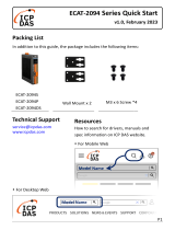
Background information: Layout of the firmware structure
The AX8000 has various slots that can be combined with a module. A module is assigned automatically to
each slot by TwinCAT Drive Manager 2, irrespective of the configuration. The modules are already contained
in the firmware of the AX8000.
A module is mandatory for some slots. In other cases the slot is always occupied by the same module,
because only one module is available (see Device Main or Axis Main, for example). Otherwise the TC Drive
Manager 2 chooses between the modules, e.g. sync servo module and linear module for the motor slot.
Fig.1: Modules and slots - basic knowledge
A module becomes effective and can send diagnostic messages as soon as it is assigned to a slot.
However, the different modules can issue the same diagnostic messages. In order for the cause of each
message to be identified and remedied, it is important to know the origin of the diagnostic message.
Therefore, in addition to the diagnostic message itself, the module that issued it needs to be known.
A module is made up of several CoE objects that contain further subindices (number after the colon). Each
subindex has a pool of parameter objects.

Introduction to the diagnostic system
Multi axis servo system - AX8000 11
Version: 1.1
Parameter objects are either standardized CoE parameter objects or Beckhoff-specific parameter objects.
Parameter object Description
0x60xx Standardized CoE parameter objects for the first axis
0x68xx Standardized CoE parameter objects for the second axis
0x3000 to 0x33FF Beckhoff-specific parameter objects for the first axis
0x3400 to 0x37FF Beckhoff-specific parameter objects for the second axis
Layout of the diagnostic system
The Axis Main slot is combined automatically with the Axis Main module. There are several CoE objects
within this module, including the object 0x10F3:xx. This contains information about the diagnostic system.
The subindices of this CoE object contain the following:
Parameter object Description
01 Maximum number of diagnostic messages
02 Latest diagnostic message
03 Latest confirmed diagnostic message
04 Availability of new diagnostic messages
05 Flags
06..255 Memory space for the last 250 diagnostic messages
The structure of the individual subindices is shown in the diagram. The parameter objects of the subindices
are described in detail below.
Structure of a diagnostic message
The following section described the parameter objects of a saved diagnostic message (subindex 06 to 255)
in the diagnosis history object 0x10F3.
A diagnostic message is displayed in hexadecimal notation and contains the following Beckhoff-specific
parameter objects:
• Diagnostic class
• Diagnostic type
• (Error) reaction
• Reset condition
In conjunction with the diagnostic class, some diagnostic messages contain further parameter objects.
Diagnostic class
A diagnostic message is assigned to a diagnostic class. There are three diagnostic classes in all:
Diagnostic class Information
1 Error An error always causes the axis to be stopped. We recommend the following procedure for the rectifica-
tion of errors:
• Disable the axis
• Rectify the error
• Reset the axis, e.g. via the NC error reset
• Enable the axis
• Put the plant into operation again
2 Warning Warnings are displayed, but the AX8000 does not react directly.
3 Information Information is displayed, but the AX8000 does not react directly.
Diagnostic messages of the diagnostic class Error have two further parameter objects: error cause and error
solution.

Introduction to the diagnostic system
Multi axis servo system - AX800012
Version: 1.1
Diagnostic type
Each diagnostic message is assigned to a diagnosis type that contains the type group of the diagnostic
object. In total, there are 20 different diagnosis type groups (see table).
The diagnosis type groups 0 to 16 differ from the rest because the error counters are read directly via the
associated CoE object. The CoE object is called 0x2C1E:x (DeviceMain error counter) and, analogous to the
diagnosis type groups, has 17 sub-objects. Each of these sub-objects has the same name as the assigned
diagnosis type group.
Diagnosis type group Description
0 Motor overload shut down Motor overloaded
1 Motor overtemperature shut down Motor temperature exceeded
2 Drive overtemperature shut down Axis module temperature exceeded
3 Control voltage error Error in the 24V power supply
4 Feedback error Error in the feedback system
5 Commutation error Commutation error
6 Overcurrent error Overcurrent error in the motor phases
7 Overvoltage error Overvoltage in DC link
8 Undervoltage error Undervoltage in DC link
9 Power supply phase error Phase error in the supply module
10 Communication error Communication error
11 TorqueOff with emergency brake Torque-free axis with emergency braking
12 Motor connection error Motor connection error
13 Safety STO error Axis enabled and STO active
14 Overspeed error Speed exceeded
15 Motor Brake connection error Motor brake connection error
16 DC link connection overcurrent error Overcurrent error in the DC link
17 Warning A warning has no effect on the AX8000.
18 Information Information has no effect on the AX8000.
19 Information without history entry Information has no effect on the AX8000.
Reaction
The AX8000 can react in different ways to a diagnostic message. See also "AX8000 Diagnostic Messages".
In total there are seven different types of reaction, sorted hierarchically.
Since not all types of reaction are implemented, the next executable type of reaction is executed in the case
of an inexecutable reaction. The lowest type of reaction in this hierarchy is "torque-free".
Execution hierarchy Type of reaction Description
1 NC control The reaction of the AX8000 is controlled by the NC. The reaction time in which
the AX8000 takes control can be parameterized (see "AX8000 Diagnostic Mes-
sages")
2 "Closed loop" ramp The axis is brought to a standstill in a controlled manner. The ramp is parame-
terizable.
3 "Open loop" ramp The axis is brought to a standstill in a controlled manner. The ramp is parame-
terizable.
4 Emergency brake The motor is ramped down.
5 Torque-free The AX8000 switches the axis torque-free.
- No Reaction No reaction takes place; the AX8000 remains in the normal operating condi-
tion.
Examples of the hierarchical reaction execution
Expected reaction according to diagnostic Reaction performed by AX8000
1 NC control 2 "Closed loop" ramp
2 "Closed loop" ramp 2 "Closed loop" ramp
3 "Open loop" ramp 5 Torque-free
4 Emergency braking 4 or 5 For asynchronous motors this is followed by DC braking, for
synchronous motors torque-free
5 Torque-free 5 Torque-free

Introduction to the diagnostic system
Multi axis servo system - AX8000 13
Version: 1.1
Object 605E
h
– Fault reaction option code
With the Fault reaction option code you can specify the reaction to the diagnosis that is to be exe-
cuted. The "Closed Loop Ramp" reaction is stored as standard.
Reset condition
Depending on the diagnostic message, reset conditions will be specified for eliminating the diagnostic
message. The following resets can be executed with the AX8000.
Diagnostic class / cause Rest possible Remedy
Error: fatal hardware or software error No Replace servo drive if necessary
Error: fatal error Yes Restart AX8000
(interrupt 24V power supply for at least 10sec.)
Error Yes Execute an NC error reset
Error due to motor replacement Yes Execute an NC error reset
Warning Not required There is no reaction by the AX8000 to any warning.
Information Not required There is no direct reaction by the AX8000 to informa-
tion.
Possible causes
All causes that could have caused the diagnostic message are listed there. Please always read all of the
causes.
Solutions
Analogous to the causes, all solutions are listed there. The ordinal numbers before the "possible causes" and
the "solutions" correspond to one another.
Readout on the AX8000 display
Supply module
Display Description
E
EtherCAT symbol flashes red
There is an EtherCAT error
P
Power symbol lights up red
There is a power supply error
P
Power symbol flashes red
There is a power supply error and the DC link is being charged or discharged
• Fast: DC link > 48V
• Slowly: DC link ≤48V
Axis module
Display Description
A
Axis symbol is flashing red-green
Axis error reaction is active
A
Axis symbol is flashing red
There is an axis error

Introduction to the diagnostic system
Multi axis servo system - AX800014
Version: 1.1
2.2 Settings with respect to the diagnostic system
Standard reactions of the AX8000 are stored for a diagnostic message of the diagnostic class Error. They
can be set individually by means of parameterization.
Object 605E
h
– Fault reaction option code
With the Fault reaction option code you can specify the reaction to the diagnosis that is to be executed. The
Closed Loop Ramp reaction is stored as standard.
The new reaction is defined by specifying the following values.
Value Error reaction Comment
2 (0x0002) Closed Loop Ramp Default value: The standard
reaction to the error is performed.
0 (0x0000) Torque-free ATTENTION! The axis is stopped
in an uncontrolled manner.
1 (0xFFFF): NC handling (the reaction is left to
the NC for a certain time before the
AX8000 "ramps down")
Note, however, that no reaction ranked higher in the hierarchy than the standard reaction may be selected.

Standard-Messages
Multi axis servo system - AX8000 15
Version: 1.1
3 Standard-Messages
3.1 0000, No Error
This Message is thrown always, if the Device enters an error-free state.
Diagnostic Code (Hex.) Diagnostic Code (Dez.)
0000 0
Class Type
Info Information
Standard Reaction Reset
No Information: No reset required.
Possible Causes Solutions
An Axis entered the error free state.
Internal: 0x0000, No Error

Standard-Messages
Multi axis servo system - AX800016
Version: 1.1
3.2 5190, Test 5V supply failed
Diagnostic Code (Hex.) Diagnostic Code (Dez.)
5190 20880
Class Type
Error Error
Standard Reaction Reset
Axis is inoperable A reset is not possible. The drive detected a fatal
hard- or software error.
Possible Causes Solutions
There is an internal hardware error. Send the AX8000 to the Beckhoff branch office that is
responsible for you.
Internal: 0x5190, Test 5V supply failed

Standard-Messages
Multi axis servo system - AX8000 17
Version: 1.1
3.3 5580, Read failure EEPROM
Impossible to read Data from the Identity EEPROM of a Pcb. (no Response)
- ID 0: ControlPcb
- ID 1: FrontPcb
- ID 2: AdditionalAxisPcb
- ID 3: DisplayPcb
- ID 6: SafetyPcb
- ID 7: CpuPcb
Diagnostic Code (Hex.) Diagnostic Code (Dez.)
5580 21888
Class Type
Error Error
Standard Reaction Reset
Axis is inoperable A reset is not possible. The drive detected a fatal
hard- or software error.
Possible Causes Solutions
There is an internal hardware error. Send the AX8000 to the Beckhoff branch office that is
responsible for you.
Internal: 0x5580, Read failure EEPROM. Pcb ID %u.

Standard-Messages
Multi axis servo system - AX800018
Version: 1.1
3.4 5581, Checksum failure EEPROM
Checksum failure in read Data from the Identity EEPROM of a Pcb. (no Response)
- ID 0: ControlPcb
- ID 1: FrontPcb
- ID 2: AdditionalAxisPcb
- ID 3: DisplayPcb
- ID 6: SafetyPcb
- ID 7: CpuPcb
Diagnostic Code (Hex.) Diagnostic Code (Dez.)
5581 21889
Class Type
Error Error
Standard Reaction Reset
Axis is inoperable A reset is not possible. The drive detected a fatal
hard- or software error.
Possible Causes Solutions
There is an internal hardware error. Send the AX8000 to the Beckhoff branch office that is
responsible for you.
Internal: 0x5581, Checksum failure EEPROM. Pcb ID %u.

Standard-Messages
Multi axis servo system - AX8000 19
Version: 1.1
3.5 5582, EEPROM contains blank Data
The Identity EEPROM of a Pcb is blank. (no Response)
- ID 0: ControlPcb
- ID 1: FrontPcb
- ID 2: AdditionalAxisPcb
- ID 3: DisplayPcb
- ID 6: SafetyPcb
- ID 7: CpuPcb
Diagnostic Code (Hex.) Diagnostic Code (Dez.)
5582 21890
Class Type
Warning Warning
Standard Reaction Reset
No Warning: No reset required.
Possible Causes Solutions
This Message is generated instead of 0x5584, if you
are using a debug Firmware or a special Prototype
Hardware.
Internal: 0x5582, EEPROM contains blank Data. Pcb ID %u.

Standard-Messages
Multi axis servo system - AX800020
Version: 1.1
3.6 5583, Unexpected EEPROM
The Identity EEPROM of a Pcb is unexpected. This Device shouldn't contain this Pcb.
- ID 0: ControlPcb
- ID 1: FrontPcb
- ID 2: AdditionalAxisPcb
- ID 3: DisplayPcb
- ID 6: SafetyPcb
- ID 7: CpuPcb
Diagnostic Code (Hex.) Diagnostic Code (Dez.)
5583 21891
Class Type
Warning Warning
Standard Reaction Reset
No Warning: No reset required.
Possible Causes Solutions
This Message is generated instead of 0x5585, if you
are using a debug Firmware.
Internal: 0x5583, Unexpected EEPROM Pcb ID %u.
/