Page is loading ...

Operating Instruction | EN
EP1918
TwinSAFE EtherCAT Box with 8 fail-safe inputs
2020-09-10 | Version: 1.1.0


Table of contents
EP1918 3Version: 1.1.0
Table of contents
1 Foreword ....................................................................................................................................................5
1.1 Notes on the documentation..............................................................................................................5
1.2 Safety instructions .............................................................................................................................6
1.2.1 Delivery state ..................................................................................................................... 6
1.2.2 Operator's obligation to exercise diligence ........................................................................ 6
1.2.3 Description of instructions.................................................................................................. 7
1.3 Documentation issue status ..............................................................................................................8
1.4 Version history of the TwinSAFE product..........................................................................................8
2 System description ...................................................................................................................................9
2.1 EtherCAT Box Modules .....................................................................................................................9
3 Product description.................................................................................................................................10
3.1 EP1918-0002...................................................................................................................................10
3.2 Intended use....................................................................................................................................11
3.3 Technical data .................................................................................................................................12
3.4 Safety parameters ...........................................................................................................................13
3.5 Safe inputs.......................................................................................................................................14
3.6 Dimensions......................................................................................................................................15
4 Operation..................................................................................................................................................16
4.1 Environmental conditions ................................................................................................................16
4.2 Installation .......................................................................................................................................16
4.2.1 Fixing ............................................................................................................................... 16
4.2.2 Connection....................................................................................................................... 16
4.2.3 EP1918 temperature measurement................................................................................. 23
4.2.4 Signal cables ................................................................................................................... 24
4.3 EP1918 configuration in TwinCAT...................................................................................................26
4.3.1 Adding an EtherCAT device ............................................................................................ 26
4.3.2 Inserting an EP1918 ........................................................................................................ 26
4.3.3 Using the integrated TwinSAFE Logic functions.............................................................. 26
4.3.4 Project design limits of the EP1918 ................................................................................. 27
4.3.5 Address settings on the TwinSAFE EtherCAT Box ......................................................... 28
4.3.6 Alias devices.................................................................................................................... 29
4.3.7 Parameters of the EP1918 .............................................................................................. 31
4.3.8 Process image of the EP1918 ......................................................................................... 34
4.4 TwinSAFE reaction times ................................................................................................................35
4.5 Diagnosis.........................................................................................................................................37
4.5.1 EtherCAT- Fieldbus LEDs ............................................................................................... 37
4.5.2 Status LEDs..................................................................................................................... 38
4.5.3 Diagnostic LEDs .............................................................................................................. 39
4.5.4 Flash code display ........................................................................................................... 40
4.5.5 Diagnostic objects............................................................................................................ 40
4.5.6 Cycle time of the safety project........................................................................................ 42
4.5.7 Diag History tab ............................................................................................................... 42
4.5.8 Diagnosis History............................................................................................................. 43

Table of contents
EP19184 Version: 1.1.0
4.6 Maintenance ....................................................................................................................................46
4.7 Service life .......................................................................................................................................46
4.8 Decommissioning ............................................................................................................................47
4.9 Firmware update of TwinSAFE products.........................................................................................48
5 Appendix ..................................................................................................................................................51
5.1 Protection classes according to IP code..........................................................................................51
5.2 Support and Service ........................................................................................................................52
5.3 Certificates.......................................................................................................................................53

Foreword
EP1918 5Version: 1.1.0
1 Foreword
1.1 Notes on the documentation
Intended audience
This description is only intended for the use of trained specialists in control and automation engineering who
are familiar with the applicable national standards.
It is essential that the following notes and explanations are followed when installing and commissioning
these components.
The responsible staff must ensure that the application or use of the products described satisfy all the
requirements for safety, including all the relevant laws, regulations, guidelines and standards.
Origin of the document
This original documentation is written in German. All other languages are derived from the German original.
Currentness
Please check whether you are using the current and valid version of this document. The current version can
be downloaded from the Beckhoff homepage at http://www.beckhoff.com/english/download/twinsafe.htm.
In case of doubt, please contact Technical Support [}52].
Product features
Only the product features specified in the current user documentation are valid. Further information given on
the product pages of the Beckhoff homepage, in emails or in other publications is not authoritative.
Disclaimer
The documentation has been prepared with care. The products described are subject to cyclical revision. For
that reason the documentation is not in every case checked for consistency with performance data,
standards or other characteristics. We reserve the right to revise and change the documentation at any time
and without prior announcement. No claims for the modification of products that have already been supplied
may be made on the basis of the data, diagrams and descriptions in this documentation.
Trademarks
Beckhoff
®
, TwinCAT
®
, EtherCAT
®
, EtherCATG
®
, EtherCATG10
®
, EtherCATP
®
, SafetyoverEtherCAT
®
,
TwinSAFE
®
, XFC
®
, XTS
®
and XPlanar
®
are registered trademarks of and licensed by Beckhoff Automation
GmbH. Other designations used in this publication may be trademarks whose use by third parties for their
own purposes could violate the rights of the owners.
Patent Pending
The EtherCAT Technology is covered, including but not limited to the following patent applications and
patents: EP1590927, EP1789857, EP1456722, EP2137893, DE102015105702 with corresponding
applications or registrations in various other countries.

Foreword
EP19186 Version: 1.1.0
EtherCAT
®
and Safety over EtherCAT
®
are registered trademarks and patented technologies, licensed by
Beckhoff Automation GmbH, Germany.
Copyright
© Beckhoff Automation GmbH & Co. KG, Germany.
The reproduction, distribution and utilization of this document as well as the communication of its contents to
others without express authorization are prohibited.
Offenders will be held liable for the payment of damages. All rights reserved in the event of the grant of a
patent, utility model or design.
Delivery conditions
In addition, the general delivery conditions of the company Beckhoff Automation GmbH & Co. KG apply.
1.2 Safety instructions
1.2.1 Delivery state
All the components are supplied in particular hardware and software configurations appropriate for the
application. Modifications to hardware or software configurations other than those described in the
documentation are not permitted, and nullify the liability of Beckhoff Automation GmbH & Co. KG.
1.2.2 Operator's obligation to exercise diligence
The operator must ensure that
• the TwinSAFE products are only used as intended (see chapter Product description);
• the TwinSAFE products are only operated in sound condition and in working order.
• the TwinSAFE products are operated only by suitably qualified and authorized personnel.
• the personnel is instructed regularly about relevant occupational safety and environmental protection
aspects, and is familiar with the operating instructions and in particular the safety instructions contained
herein.
• the operating instructions are in good condition and complete, and always available for reference at the
location where the TwinSAFE products are used.
• none of the safety and warning notes attached to the TwinSAFE products are removed, and all notes
remain legible.

Foreword
EP1918 7Version: 1.1.0
1.2.3 Description of instructions
In these operating instructions the following instructions are used.
These instructions must be read carefully and followed without fail!
DANGER
Serious risk of injury!
Failure to follow this safety instruction directly endangers the life and health of persons.
WARNING
Risk of injury!
Failure to follow this safety instruction endangers the life and health of persons.
CAUTION
Personal injuries!
Failure to follow this safety instruction can lead to injuries to persons.
NOTE
Damage to the environment/equipment or data loss
Failure to follow this instruction can lead to environmental damage, equipment damage or data loss.
Tip or pointer
This symbol indicates information that contributes to better understanding.

Foreword
EP19188 Version: 1.1.0
1.3 Documentation issue status
Version Comment
1.1.0 • Chapter EP1918 temperature measurement updated
1.0.0 • First release
0.4 • Technical data for sensor supply updated
• Technical data for current consumption updated
0.3 • Technical data updated
0.2 • Note on commissioning test added
• Version history of the TwinSAFE product added
• Note on safe inputs added
0.1 • First draft
1.4 Version history of the TwinSAFE product
This version history lists the software and hardware version numbers. A description of the changes
compared to the previous version is also given.
Updated hardware and software
TwinSAFE products are subject to a cyclical revision. We reserve the right to revise and change the
TwinSAFE products at any time and without prior notice.
No claims for changes to products already delivered can be asserted from these hardware and/or
software changes.
A description of how a firmware (software) update can be performed can be found in chapter Firmware
update of TwinSAFE products [}48].
Date Software version Hardware version Modifications
2020-05-20 01 00 First release of the EP1918-0002

System description
EP1918 9Version: 1.1.0
2 System description
2.1 EtherCAT Box Modules
The EtherCAT system has been extended with EtherCAT Box modules with protection class IP67. Through
the integrated EtherCAT interface the modules can be connected directly to an EtherCAT network without an
additional Coupler Box. The high-performance of EtherCAT is thus maintained into each module.
The extremely low dimensions of only e.g.126x30x26.5mm are identical to those of the Fieldbus Box
extension modules. They are thus particularly suitable for use where space is at a premium. The small mass
of the EtherCAT modules facilitates applications with mobile I/O interface (e.g. on a robot arm). The
EtherCAT connection is established via screened M8 connectors.
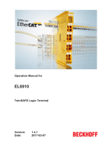
Fig.1: EtherCAT Box modules extend the EtherCAT system with IP67 protection
The robust design of the EtherCAT Box modules enables them to be used directly at the machine. Control
cabinets and terminal boxes are now no longer required. The modules are fully sealed and therefore ideally
prepared for wet, dirty or dusty conditions.
Pre-assembled cables significantly simplify EtherCAT and signal wiring. Very few wiring errors are made, so
that commissioning is optimized. In addition to pre-assembled EtherCAT, power and sensor cables, field-
configurable connectors and cables are available for maximum flexibility. Depending on the application, the
sensors and actuators are connected through M8 or M12 connectors.
Basic EtherCAT documentation
You will find a detailed description of the EtherCAT system in the Basic System Documentation for
EtherCAT, which is available for download from our website (www.beckhoff.com) under Downloads.

Product description
EP191810 Version: 1.1.0
3 Product description
3.1 EP1918-0002
The EP1918-0002 TwinSAFE EtherCAT Box is a digital EtherCAT Box for sensors with potential-free
contacts for 24V
DC
. It has eight fail-safe inputs.
The EP1918-0002 meets the requirements of the following standards:
• EN 61508:2010 (SIL 3)
• EN 62061:2005/A2:2015 (SILCL3)
• EN ISO 13849-1:2015 (Cat.4,PLe)
Fig.2: EP1918-0002 - TwinSAFE EtherCAT Box with 8 fail-safe inputs

Product description
EP1918 11Version: 1.1.0
3.2 Intended use
WARNING
Caution - Risk of injury!
TwinSAFE components may only be used for the purposes described below!
The TwinSAFE EtherCAT Box expands the application range of the Beckhoff system with functions that
enable it to be used for machine safety applications. The TwinSAFE Boxes are designed for machine safety
functions and directly associated industrial automation tasks. They are therefore only approved for
applications with a defined fail-safe state. This safe state is the wattless state. Fail-safety according to the
relevant standards is required.
The TwinSAFE EtherCAT Box allows the connection of:
24V
DC
sensors such as
• emergency stop push buttons, rope pull switches, position switches, two-hand switches, safety mats,
light curtains, light barriers, laser scanners etc.
• Safe sensors, which use a 24V
DC
supply and send safe OSSD signals.
WARNING
The fail-safe principle!
The basic rule for a safety system such as TwinSAFE is that failure of a part, a system component or the
overall system must never lead to a dangerous condition. The safe state is always the switched off and wat-
tless state.
WARNING
Power supply from SELV/PELV power supply unit!
The TwinSAFE components must be supplied with 24V
DC
by an SELV/PELV power supply unit with an out-
put voltage limit U
max
of 36V
DC
. Failure to observe this can result in a loss of safety.
WARNING
System limits
The TÜV SÜD certificate applies to this TwinSAFE component, the function blocks available in it, the docu-
mentation and the engineering tool. TwinCAT 3.1 and the TwinSAFE Loader are permitted as engineering
tools. Any deviations from these procedures or tools, particularly externally generated xml files for Twin-
SAFE import or externally generated automatic project creation procedures, are not covered by the certifi-
cate.
WARNING
Commissioning test
Before the EP1918-0002 can be used for the safety task, the user must carry out a commissioning test so
that sensor and actuator wiring faults can be ruled out.
CAUTION
Follow the machinery directive!
The TwinSAFE components may only be used in machines as defined in the machinery directive.
CAUTION
Ensure traceability!
The buyer has to ensure the traceability of the device via the serial number.

Product description
EP191812 Version: 1.1.0
3.3 Technical data
Product designation EP1918-0002
Fieldbus EtherCAT
Number of inputs 8
Connecting the inputs M12
Status display 8 (one green LED per input), 5 diagnostic LEDs, 2 LEDs for Us/Up,
2 LEDs for EtherCAT Link/Act
Response time
(read input/write to E-bus)
typically: 3ms,
maximum: see fault response time
Watchdog time adjustable from 2ms to 60s
Fault response time ≤ watchdog time
Cable length between sensor and EtherCAT Box Unshielded: 100m max. (at 0.75 or 1mm²)
Shielded: 100m max. (at 0.75 or 1mm²)
Output current of the clock outputs
(Input Power Mode parameter: Diag Testpulse)
typically 10mA
Output current of sensor supply
(Input Power Mode parameter: PowerMode A/B)
max. 250mA
Max. output current clock outputs/sensor supply in the
event of an error
max. 3A (the duration depends on the overtemperature-related shutdown of
the output driver)
Input process image 7bytes (via FSoE if using the default project)
Output process image 6bytes (via FSoE if using the default project)
Supply voltage for the EP1918 24V
DC
(–15%/+20%)
Current consumption U
S
(wired with 8 potential-free contacts)
8 channels occupied: typically 100mA
0 channels occupied: typically 91mA
(provide 4A fuse)
Current consumption U
P
(wired with 8 potential-free contacts)
8 channels occupied: approx. 60mA
0 channels occupied: approx. 35mA
(provide 4A fuse)
Power dissipation of the EtherCAT Box typically 3.8watts
Electrical isolation (between the channels) no
Electrical isolation
(between the channels and EtherCAT)
yes
Insulation voltage (between the channels and Ether-
CAT, under common operating conditions)
Insulation tested with 500V
DC
Dimensions (WxHxD) 30 mm x 126 mm x 26.5 mm
Housing material PA66-GV 30 (WELLAMID)
Flame Class: V-0
Sealing compound Polyurethane PU552L
Flame Class: V-0
Weight approx.170g
Permissible ambient temperature
(operation)
-25°C to +60°C
Permissible ambient temperature
(transport/storage)
-40°C to +85°C
Permissible air pressure
(operation/storage/transport)
750hPa to 1100hPa
(this is equivalent to an altitude of approx. -690m to 2450m above sea level
assuming an international standard atmosphere)
Inadmissible operating conditions TwinSAFE EtherCAT boxes must not be used under the following conditions:
• under the influence of ionizing radiation (exceeding the natural
background radiation)
• in corrosive environments
EMC immunity/emission conforms to EN61000-6-2/ EN61000-6-4 (EMC ZoneB)
Vibration resistance conforms to EN60068-2-6
5 Hz ≤ f < 8.4 Hz (3.5 mm peak)
8.4 Hz ≤ f < 150 Hz (10 m/s
2
peak)
Shock resistance conforms to EN60068-2-27
15g with pulse duration 11ms in all three axes
Protection class (when screwed together) IP67 (according to EN60529)
Correct installation position variable
Approvals CE, TÜV SÜD

Product description
EP1918 13Version: 1.1.0
Derating table for altitudes above 2000m
The derating table (table 8) from the IEC61131-2:2017 standard can be referred to for the use of the
TwinSAFE components above the specified maximum altitude.
Altitude in m Derating factor for the temperature
1
0 to 2000
2
1.0
3000 0.9
4000 0.8
5000 0.7
Note: Linear interpolation is permissible between the altitudes
1)
Ambient temperature of the device at an altitude of 2000m
2)
The air pressure and air density increase as the altitude decreases. Therefore the derating factor for 0 to
2000 m (1.0) is used for altitudes below sea level.
Calculation example
In the following example the calculation is performed for a TwinSAFE component at an operating altitude of
4000m.
Permissible ambient temperature up to 2000 m above sea level = 55°C
Permissible ambient temperature up to 4000m above sea level = 55°C * 0.8 = 44°C
CAUTION
Compliance with the temperature limits
The TwinSAFE component has a maximum internal temperature at which a switch-off takes place. This is
designed for the maximum permissible ambient temperature. If the derating factor for the temperature for
higher altitudes is used, the user is solely responsible for ensuring that the calculated maximum ambient
temperature is complied with.
3.4 Safety parameters
Characteristic numbers EP1918-0002
Lifetime [a] 20
Proof test interval [a] not required
1
PFH
D
5.00E-09
PFD 6.90E-05
MTTF
D
high (875a)
DC high (98,6% CAT 4)
Performance level PL e
Category 4
HFT 1
Element classification
2
Type B
1)
Special proof tests throughout the service life of the EtherCAT Box are not required.
2)
Classification according to EN 61508-2:2010 (see chapter 7.4.4.1.2 and 7.4.4.1.3)
The EP1918-0002 TwinSAFE EtherCAT Box can be used for fail-safe applications within the meaning of
IEC61508:2010 up to SIL3 and ENISO13849-1:2015 up to PLe(Cat.4).
Further information on calculating or estimating the MTTF
D
value from the PFH
D
value can be found in the
TwinSAFE Application Guide or in ENISO13849-1:2015, TableK.1.
In terms of safety-related parameters, the Safety-over-EtherCAT communication is already considered with
1% of SIL3 according to the protocol specification.

Product description
EP191814 Version: 1.1.0
3.5 Safe inputs
The safe input modules and corresponding clock outputs have a two-channel design. This has the
advantage that a two-channel safe sensor with an M12 connection can be used, and a fault such as cross-
circuit or external feed results in shutdown of the whole module.
DANGER
Clocked signals inside a sheathed cable
If clocked signals (clock outputs for the safe inputs) of different modules are used within a sheathed cable,
a fault of one module, such as cross-circuit or external feed, must lead to the switch-off of all of these mod-
ules. This is achieved by setting the Module Fault Link active parameter for all modules involved. This pa-
rameter is set to TRUE by default.
DANGER
Safe inputs in Cat.4 / PL e
If two safe input channels are to be used in a category 4 structure that are not on one M12 connector,
please make sure to combine always an even and an odd channel number.

Product description
EP1918 15Version: 1.1.0
3.6 Dimensions
Fig.3: EP1918-0002 - Dimensions
The TwinSAFE EtherCAT Box has the following dimensions.
Width 30.0 mm
Height 126.0 mm
Depth 26.5 mm
When fully wired, the connected cables increase the total depth of the module.

Operation
EP191816 Version: 1.1.0
4 Operation
4.1 Environmental conditions
Please ensure that the TwinSAFE Boxes are only transported, stored and operated under the specified
conditions (see technical data)!
WARNING
Risk of injury!
The TwinSAFE EtherCAT boxes must not be used under the following conditions.
• under the influence of ionizing radiation (that exceeds the level of the natural environmental radiation)
• in corrosive environments
NOTE
Electromagnetic compatibility
The TwinSAFE components comply with the current standards on electromagnetic compatibility with regard
to spurious radiation and immunity to interference in particular.
However, in cases where devices such as mobile phones, radio equipment, transmitters or high-frequency
systems that exceed the interference emissions limits specified in the standards are operated near Twin-
SAFE components, the function of the TwinSAFE components may be impaired.
4.2 Installation
4.2.1 Fixing
NOTE
Protect connectors against soiling!
Protect all connections from contamination during installation and operation of the modules! Protection
class IP67 is only guaranteed if all cables and plug connectors are connected, and unused connections are
protected with the appropriate cover plugs!
Connector sets see catalog.
• Modules with narrow housing are installed with two M3 screws.
• Modules with wide housing are installed with two M3 screws in the mounting holes in the corners or
two M4 screws in the central fastening holes (see also chapter Power connection and grounding).
• The bolts must be longer than 15mm. The fastening holes in the modules have no thread.
• Note when mounting that the overall height is increased further by the fieldbus connections.
4.2.2 Connection
4.2.2.1 Nut torque for connectors
M8 connector
We recommend fastening the M8 connector with a torque of 0.4Nm. A max. torque of 0.5Nm is also
permissible if using a torque screwdriver (Beckhoff article ZB8800).

Operation
EP1918 17Version: 1.1.0
Fig.4: EtherCAT Box with M8 plug connectors
M12 connector
We recommend fastening the M12 connector with a torque of 0.6Nm.
Fig.5: EtherCAT Box with M8 and M12 connectors
7/8" plug connectors
We recommend fastening the 7/8" plug connectors with a torque of 1.5Nm.
Fig.6: 7/8" plug connectors
Torque wrench
Fig.7: Torque wrench ZB8801
NOTE
Ensure the proper torque is used
Use torque wrenches available from Beckhoff to tighten the connectors (see accessories)!

Operation
EP191818 Version: 1.1.0
4.2.2.2 EtherCAT connection
The EtherCAT Box (EPxxxx) has two M8 connectors marked green for the incoming and outgoing EtherCAT
connection.
Fig.8: EtherCAT connection 30 mm housing M8
Connection
There are various different standards for the assignment and colors of connectors and cables for EtherCAT.
EtherCAT Connector Cable Standard
Signal Description M8 ZB9010, ZB9020,
ZK1090-6292
ZB903x,
ZK1090-31xx
TIA-568B
Tx + Transmit Data+ Pin 1 yellow
1
orange/white
2
white/orange
Tx - Transmit Data- Pin 4 orange
1
orange
2
orange
Rx + Receive Data+ Pin 2 white
1
blue/white
2
white/green
Rx - Receive Data- Pin 3 blue
1
blue
2
green
Shield Shield Housing Shield Shield Shield
1)
Core colors according to EN61918
2)
Core colors
4.2.2.3 EtherCAT cables
For connecting EtherCAT devices only Ethernet cables that meet the requirements of at least category 5
(CAT5) according to EN 50173 or ISO/IEC 11801 should be used.
Wiring recommendations
Detailed recommendations for EtherCAT wiring can be found in the documentation "Design recom-
mendations for EtherCAT/Ethernet infrastructure", which is available for download from www.Beck-
hoff.de.
EtherCAT uses four cable wires for signal transmission. Due to automatic cable detection (auto-crossing)
symmetric (1:1) or cross-over cables can be used between EtherCAT devices from BECKHOFF.

Operation
EP1918 19Version: 1.1.0
4.2.2.4 Power connection and grounding
This chapter provides basic information about the power supply and grounding of the EP1918 TwinSAFE
EtherCAT Box. In particular, please note that the General information on connecting the functional earth only
serves as an example.
Supply voltages (power connection)
The supply and distribution of the supply voltages takes place via the connections:
• Us/Up IN for feeding in the supply voltages
• Us/Up OUT for distribution of the supply voltages.
Both connections have an M8 thread and are located to the left (Us/Up IN) and right (Us/Up OUT) of the
TwinSAFE EtherCAT Box (see figure: EP1918 - power connection and FE).
Information: An overview of pin assignment for the two connections can be found later in this chapter.
General information for connecting the functional earth
The earth connection of the EP1918 (see figure: EP1918 - power connection and FE) and the grounding
sleeves in the fastening holes for the M3 screws for fixing the EtherCAT Box are internally connected. The
earth connection is capacitively connected to Us, Up and the shield of the EtherCAT connection.
The earthing screw is installed in the factory. An additional M3 ring cable lug and the earthing cable are
required for the installation
To provide functional earthing , if possible the connection should:
• have a large surface
• have low resistance and
• be permanent.
In order to establish a permanent connection, all operating states of the machine, such as vibrations, must
be taken into account.
NOTE
Connecting the functional earth
The functional earth connection should have low resistance and a large surface.
EP1918 – Power connection and functional earth
M8 - pin assignment

Operation
EP191820 Version: 1.1.0
Contact Voltage
1 Control voltage Us, +24V
DC
(provide a 4A fuse)
2 Peripheral voltage Up, +24V
DC
(provide a 4A fuse)
3 GND Us
4 GND Up
Connecting the functional earth
The contacts of the M8 plug connectors can conduct a maximum current of 4A.
Two LEDs indicate the status of the supply voltages.
NOTE
Do not confuse the power port with EtherCAT port!
Never connect the power cables (M8, 24V
DC
) to the green-marked EtherCAT sockets of the EtherCAT Box
Modules. This can cause the destruction of the modules!
Control voltage Us
The fieldbus and the processor logic are supplied from the 24 V
DC
control voltage Us. The control voltage is
electrically isolated from the fieldbus circuitry.
Peripheral voltage Up
The peripheral voltage Up supplies the digital clock outputs and the safe inputs.
Redirection of the supply voltages
The power IN and OUT connections are bridged in the module. Hence, the supply voltages Us and Up can
be passed from EtherCATBox to EtherCATBox in a simple manner.
CAUTION
Note the maximum current!
Also ensure when forwarding the supply voltages Us and Up that the maximum permissible current of 4A
for each contact of the M8 plug connector is not exceeded!
/