Page is loading ...

Installation
Operation
Maintenance
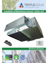
T-Series Climate Changer™
Air Handlers
Sizes 3 to 100
Part No. X39510024010A
January 2008
CLCH-SVX06A-EN

© 2008 Trane All rights reserved
Warnings and Cautions
Protecting the Environment
World environmental scientists have concluded, based on the best currently available
evidence, that ozone in our upper atmosphere is being reduced due to the release of CFC
(chlorofluorocarbon) fully halogenated compounds.
Trane urges that all HVAC servicers working on Trane equipment, or any manufacturer’s
products, make every effort to eliminate, if possible, or vigorously reduce the emission
of CFC, HCFC (halocarbon that contains fluorine, chlorine, carbon, and hydrogen), and
HFC (halocarbon that contains only fluorine, carbon, and hydrogen) refrigerants to the
atmosphere resulting from installation, operation, routine maintenance, or major service
on this equipment. Always act in a responsible manner to conserve refrigerants for
continued use even when acceptable alternatives are available.
Refrigerant used in any type of air-conditioning or refrigerating equipment should be
recovered for reuse, recovered and/or recycled for reuse, reprocessed (reclaimed), or
properly destroyed, whenever it is removed from equipment. Never release it to the
atmosphere!
NOTICE:
Warnings and Cautions appear at appropriate sections throughout this manual. Read these carefully.
WARNING
...indicates a potentially hazardous situation which, if not avoided, could result in death or serious injury.
CAUTION
...indicates a potentially hazardous situation which, if not avoided, may result in minor or moderate injury.
It may also be used to alert against unsafe practices.
CAUTION
...indicates a situation that may result in equipment or property-damage-only accidents.

CLCH-SVX06A-EN • T-Series Climate Changer Air Handler 3
Warnings and Cautions
WARNING
Equipment Damage From Ultraviolet (UV) Lights!
Trane does not recommend field-installation of ultraviolet lights in its air handling
equipment for the intended purpose of improving indoor air quality. High intensity
C-band ultraviolet light is known to severely damage polymer (plastic) materials and
poses a personal safety risk to anyone exposed to the light without proper personal
protective equipment (could cause damage to eyes and skin). Polymer materials
commonly found in HVAC equipment that may be susceptible include insulation on
electrical wiring, fan belts, thermal insulation, various fasteners and bushings.
Degradation of these materials can result in serious damage to the equipment.
Trane accepts no responsibility for the performance or operation of our air handling
equipment in which ultraviolet devices were installed outside of the Trane factory.
Ultraviolet (UV) Germicidal Irradiation Lights (optional)
The United States Environmental Protection Agency (EPA) believes that molds and
bacteria inside buildings have the potential to cause health problems in sensitive
individuals. If specified, Trane provides ultraviolet lights (UV-C) as a factory-engineered
and installed option in select commercial air handling products for the purpose of
reducing microbiological growth (mold and bacteria) within the equipment. When
factory provided, polymer materials that are susceptible to deterioration by the UV-C
light will be substituted or shielded from direct exposure to the light. In addition, UV-C
radiation can damage human tissue, namely eyes and skin. To reduce the potential for
inadvertent exposure to the lights by operating and maintenance personnel, electrical
interlocks that automatically disconnect power to the lights are provided at all unit entry
points to equipment where lights are located.

4 CLCH-SVX06A-EN
Contents
Warnings and Cautions . . . . . . . . . . . . . . . . . . . . . . . . . . . . . . . . . . . . . . . . . . . . .2
Protecting the Environment . . . . . . . . . . . . . . . . . . . . . . . . . . . . . . . . . . . . . . . 2
Ultraviolet (UV) Germicidal Irradiation Lights (optional) . . . . . . . . . . . . . . . . 3
Description . . . . . . . . . . . . . . . . . . . . . . . . . . . . . . . . . . . . . . . . . . . . . . . . . . . . . . .6
Overview of Manual . . . . . . . . . . . . . . . . . . . . . . . . . . . . . . . . . . . . . . . . . . . . . 6
Nameplate . . . . . . . . . . . . . . . . . . . . . . . . . . . . . . . . . . . . . . . . . . . . . . . . . . . . . 6
General Information . . . . . . . . . . . . . . . . . . . . . . . . . . . . . . . . . . . . . . . . . . . . . . .7
Operating Environment . . . . . . . . . . . . . . . . . . . . . . . . . . . . . . . . . . . . . . . . . . 7
Unit Description . . . . . . . . . . . . . . . . . . . . . . . . . . . . . . . . . . . . . . . . . . . . . . . . . 7
Factory-Mounted Controls . . . . . . . . . . . . . . . . . . . . . . . . . . . . . . . . . . . . . . . . 8
Wiring . . . . . . . . . . . . . . . . . . . . . . . . . . . . . . . . . . . . . . . . . . . . . . . . . . . . . . . . . 9
Pre-Installation Requirements . . . . . . . . . . . . . . . . . . . . . . . . . . . . . . . . . . . . . .10
Inspection Checklist . . . . . . . . . . . . . . . . . . . . . . . . . . . . . . . . . . . . . . . . . . . . 10
Assembly Hardware . . . . . . . . . . . . . . . . . . . . . . . . . . . . . . . . . . . . . . . . . . . . 11
Resolving Shipping Damage . . . . . . . . . . . . . . . . . . . . . . . . . . . . . . . . . . . . . 11
Storage Recommendations . . . . . . . . . . . . . . . . . . . . . . . . . . . . . . . . . . . . . . 12
Preparing the Unit Site . . . . . . . . . . . . . . . . . . . . . . . . . . . . . . . . . . . . . . . . . . 13
Unit Dimensions and Weights . . . . . . . . . . . . . . . . . . . . . . . . . . . . . . . . . . . . . .15
Service Clearances . . . . . . . . . . . . . . . . . . . . . . . . . . . . . . . . . . . . . . . . . . . . . 15
Installation-Mechanical . . . . . . . . . . . . . . . . . . . . . . . . . . . . . . . . . . . . . . . . . . . . 22
Lifting and Rigging . . . . . . . . . . . . . . . . . . . . . . . . . . . . . . . . . . . . . . . . . . . . . 22
Assembly Checklist . . . . . . . . . . . . . . . . . . . . . . . . . . . . . . . . . . . . . . . . . . . . . 26
Assembling the Unit . . . . . . . . . . . . . . . . . . . . . . . . . . . . . . . . . . . . . . . . . . . . 28
Filters . . . . . . . . . . . . . . . . . . . . . . . . . . . . . . . . . . . . . . . . . . . . . . . . . . . . . . . . 34
Fan Section . . . . . . . . . . . . . . . . . . . . . . . . . . . . . . . . . . . . . . . . . . . . . . . . . . . 40
Unit Isolation . . . . . . . . . . . . . . . . . . . . . . . . . . . . . . . . . . . . . . . . . . . . . . . . . . 41
Dampers . . . . . . . . . . . . . . . . . . . . . . . . . . . . . . . . . . . . . . . . . . . . . . . . . . . . . . 44
Duct Connections . . . . . . . . . . . . . . . . . . . . . . . . . . . . . . . . . . . . . . . . . . . . . . 46
Installation - Piping . . . . . . . . . . . . . . . . . . . . . . . . . . . . . . . . . . . . . . . . . . . . . . .49
Coil Piping and Connections . . . . . . . . . . . . . . . . . . . . . . . . . . . . . . . . . . . . . 49
Examples of Field-Installed Evaporator Piping . . . . . . . . . . . . . . . . . . . . . . . 61
Installation - Electrical . . . . . . . . . . . . . . . . . . . . . . . . . . . . . . . . . . . . . . . . . . . . .67

CLCH-SVX06A-EN 5
Contents
Controls Interface . . . . . . . . . . . . . . . . . . . . . . . . . . . . . . . . . . . . . . . . . . . . . . . . .71
Connecting the operator display . . . . . . . . . . . . . . . . . . . . . . . . . . . . . . . . . . 71
Setting up the operator display . . . . . . . . . . . . . . . . . . . . . . . . . . . . . . . . . . . 71
Calibrating the operator display . . . . . . . . . . . . . . . . . . . . . . . . . . . . . . . . . . 72
Adjusting brightness and contrast . . . . . . . . . . . . . . . . . . . . . . . . . . . . . . . . . 72
External communications port . . . . . . . . . . . . . . . . . . . . . . . . . . . . . . . . . . . . 72
Pre-Start . . . . . . . . . . . . . . . . . . . . . . . . . . . . . . . . . . . . . . . . . . . . . . . . . . . . . . . .73
Start-Up . . . . . . . . . . . . . . . . . . . . . . . . . . . . . . . . . . . . . . . . . . . . . . . . . . . . . . . .76
Unit Operation . . . . . . . . . . . . . . . . . . . . . . . . . . . . . . . . . . . . . . . . . . . . . . . . . 76
External Insulating Requirements . . . . . . . . . . . . . . . . . . . . . . . . . . . . . . . . . 84
Routine Maintenance . . . . . . . . . . . . . . . . . . . . . . . . . . . . . . . . . . . . . . . . . . . . . .85
Maintenance Checklist . . . . . . . . . . . . . . . . . . . . . . . . . . . . . . . . . . . . . . . . . . 86
Air Filters . . . . . . . . . . . . . . . . . . . . . . . . . . . . . . . . . . . . . . . . . . . . . . . . . . . . . 87
Drain Pans . . . . . . . . . . . . . . . . . . . . . . . . . . . . . . . . . . . . . . . . . . . . . . . . . . . . 88
Fans . . . . . . . . . . . . . . . . . . . . . . . . . . . . . . . . . . . . . . . . . . . . . . . . . . . . . . . . . 89
Coils . . . . . . . . . . . . . . . . . . . . . . . . . . . . . . . . . . . . . . . . . . . . . . . . . . . . . . . . . 92
Coil Winterization . . . . . . . . . . . . . . . . . . . . . . . . . . . . . . . . . . . . . . . . . . . . . . 94
Ultraviolet (UV) Light Maintenance . . . . . . . . . . . . . . . . . . . . . . . . . . . . . . . . 97
Diagnostics . . . . . . . . . . . . . . . . . . . . . . . . . . . . . . . . . . . . . . . . . . . . . . . . . . . . .100

6 T-Series Climate Changer Air Handler IOM • CLCH-SVX06A-EN
Description
Overview of Manual
Use this manual to install, startup, operate, and maintain the T-Series Climate Changer™
air handler. Carefully review the procedures discussed in this manual to minimize
installation and startup difficulties.
Nameplate
Each T-Series section is provided with a nameplate/label (see Figure 1), which identifies
the type of section, customer tagging information, the section serial number, the section
position, and the service model number.
Note: This information is required when ordering parts or requesting service for a
T-Series air handler.
Figure 1. T-Series air handler section nameplate
Module type
Module location
in direction of
airflow
Module serial
number
Unit tagging
Module service
model number
Additional module
specific information:
-Filter sizes
-Fan motor data
-Coil(s) service
model number
Trane order
number
Unit level
serial number
and service
model number
Controls serial
number and
service model
number
Agency listing
and/or agency
certification
symbols

CLCH-SVX06A-EN • T-Series Climate Changer Air Handler 7
General Information
Operating Environment
The T-Series Climate Changer air handler is a central station outdoor air handler. When
considering the placement of the T-Series air handler, it is important to consider the
operating environment. The acceptable ambient temperature range for unit operation is
-40ºF to 140ºF (-40ºC to 60ºC).
For heating applications, a special motor may be required to withstand the higher
temperatures. Motors with Class B insulation are acceptable for ambient temperatures
up to 104º F, while motors with Class F insulation can withstand ambient temperatures
to +140º F (60º C).
Note: Units with UL approval have a maximum ambient temperature requirement of
104ºF. The customer should provide adequate freeze protection for the coils. See
“Coil Winterization,” on page 94 for more information.
Unit Description
The T-Series Climate Changer air handler is an outdoor air handler designed for a variety
of controlled-air applications. The basic unit consists of a fan, heating and/or cooling
coils, filters, and dampers.
T-Series air handlers ship as complete assemblies or in sub-assemblies if shipping splits
are required. Some assembly is required when the unit ships in subassemblies.
A wide variety of components is available for the T-Series air handler, including
numerous fan, coil, and filter options, access sections, diffusers, discharge plenums,
face-and-bypass sections, UL-approved electric heat sections, humidifiers, mixing boxes,
moisture eliminator sections, exhaust dampers, controls, blenders and airflow
monitoring stations.
For more information, refer to the following documents, available from your local Trane
sales engineer:
• T-Series air handler catalog, CLCH-DS-9
• Gas Heat for M-Series and T-Series Climate Changer™ Air Handlers
– CLCH-SVX04C-EN
• Energy Wheels for T-Series Climate Changer™ Air Handlers
– CLCH-SVX01B-EN
• LJ Wing Coils - installation manuals available from www.ljwing.com
– IOMIFB-5
– IOMVIFB-5
• Humidifiers - installation manual available from www.armstrong-intl.com
– Armstrong Bulletin No. 560-G

8 T-Series Climate Changer Air Handler • CLCH-SVX06A-EN
General Information
Factory-Mounted Controls
The T-Series air handler is available with a wide selection of factory-mounted controls,
including controllers, motor starters, and variable frequency drives (VFD).
Most control components are mounted inside the unit. Depending on the system
configuration, this may include damper actuators, dirty filter switches, averaging
temperature sensors, and low limit switches. VFDs, starters, controllers, control
transformers, static pressure transducers, DC power supplies, and customer interface
relays will be in enclosures mounted on the inside of the unit.
Small items that cannot be factory-mounted, such as space temperature sensors, outside
air temperature sensors, and humidity sensors, will ship inside the control enclosures,
or packaged and shipped inside the fan or mixing box section. Larger items are shipped
inside the fan section.
Note: All control valves ship directly to the “ship-to address” from the vendor unless
another address is given on the Trane sales order.
All factory-mounted control systems (controls that are factory-wired to a unit controller
or termination strip) ordered without starters or variable-frequency drives (VFDs) are
provided with 120 to 24 Vac control transformers mounted and wired in the auxiliary
control panel. The customer must provide 120 Vac control power, 50/60 Hz, typically
3 amps for unit sizes 3 to 57 and 5 amps for unit sizes 66 to 100. A dedicated 15-amp circuit
is recommended.
Factory-mounted control systems ordered with factory-mounted starters or VFDs are
supplied with line to 24 Vac control transformers. No additional power wiring is required.
Pre-Packaged Solutions for Controls
If the T-Series air handler has been selected using one of Trane’s pre-packaged solutions
options for controls, there are a number of resources available to aid in commissioning
and start-up of the unit. These resources include commissioning sheets, graphics and
technical application notes. The technical application notes include the control
sequencing, Trane Graphic Programming (TGP) and Rover set-up files for the specific
unit selected. These resources are available through your local Trane sales office.
For a more in-depth understanding of controls, refer to the following manuals:
• For factory-configured AH540/AH541 controllers
– CNT-SVX05B-EN
• For programmable MP580 controllers
– CNT-SVP01A-EN
• For hardware installation
– CNT-SVN01A-EN
• For Trane TR1 Drives (from Danfoss)
– TR1-SVX10A-EN

CLCH-SVX06A-EN • T-Series Climate Changer Air Handler 9
General Information
Wiring
WARNING
Grounding Required!
All field-installed wiring must be completed by qualified personnel. All field-installed
wiring must comply with NEC and applicable local codes. Failure to follow these
instructions could result in death or serious injuries.
Entrances are provided for field-installation of high and low voltage wiring through a
pipe/nipple connection in the base of the unit. The low- and high-voltage connections are
on opposite sides of the unit on sizes 3 - 57 and on the same side for sizes 66 - 100. Before
installation, consider overall unit serviceability and accessibility before mounting,
running wires (power), making penetrations, or mounting any components to the
cabinet.
Wiring to T-Series units must be provided by the installer and must comply with all
national and local codes. The fan motor nameplate includes a wiring diagram. If there are
any questions concerning the wiring of the motor, write down the information on the
motor nameplate and contact your local Trane sales office.

10 T-Series Climate Changer Air Handler • CLCH-SVX06A-EN
Pre-Installation Requirements
The T-Series air handler typically ships as a complete air handler, but if shipping splits
are required, it can ship in individual sections, or in section sub-assemblies. Unit sizes
3 to 100 have an integral base rail.
The specifications provided in Table 1 indicate the maximum values for a single-piece
shipment. If either the maximum weight or maximum length is exceeded, the T-Series
unit will ship in multiple pieces.
Note: These limits are based on a four-point lift.
Inspection Checklist
Upon receipt of the air-handling unit, prior to unloading, visually check the components
for any damage that may have occurred during shipment. Conduct a thorough inspection
immediately before accepting the shipment.
Note: Delivery cannot be refused. Trane is not responsible for shipping damage.
• Check all access doors to confirm the latches and hinges are not damaged.
• Inspect the interior of each section for any internal damage.
• Concealed damage must be reported within 15 days of receipt.
• Inspect the coils for damage to the fin surface and/or coil connections.
• If the unit was ordered with factory-mounted controls, locate all sensors.
• Items that cannot be factory-mounted should ship inside the control enclosures, or
should be packaged inside the fan or mixing box section.
• Check all control devices attached to the unit exterior and confirm they are not
damaged.
• Manually rotate the fan wheel to ensure free movement of the shaft, bearings, and
drive.
• Inspect the fan housing for any foreign objects.
• If the unit shipped in sub-assemblies, locate the assembly hardware, which should be
packaged and shipped inside the fan or mixing box section.
Table 1. Shipping length and weight limitations for single piece shipments
Unit Size Max Weight (lbs) Max Length (in)
3-40 15,000 360
50 15,000 336
57-66 15,000 112
80 15,000 120
100 15,000 124

CLCH-SVX06A-EN • T-Series Climate Changer Air Handler 11
Pre-Installation Requirements
Assembly Hardware
Trane air handlers ship with all necessary assembly hardware and gasket material. This
hardware is packaged in either a clear plastic envelope or cardboard box and can be
found inside the fan, mixing box, or access section. If there is not enough space inside
the section, a crate or pallet will be loaded onto the bed of the truck. Check the Parts List
on the Field Assembly drawing against the contents of the crate. Do not proceed with unit
assembly until verification that all materials are present. Sometimes it is necessary to use
more than one section to ship hardware. Please check all sections thoroughly before
contacting your local Trane sales engineer to report missing hardware.
Resolving Shipping Damage
Trane air handlers ship free-on-board (FOB) ship dock, meaning that the unit belongs to
the customer the moment the delivery truck leaves the factory shipping dock. If damage
has occurred to the unit during shipment, follow these instructions:
Note: Trane is not responsible for shipping damage.
1. Make specific notation describing the damage on the freight bill. Take photos of the
damaged material if possible.
2. Report all claims of shipping damage to the delivering carrier immediately and
coordinate carrier inspection, if necessary.
Note: Do not attempt to repair the unit without consulting the delivering carrier.
3. Notify your Trane sales representative of the damage and arrange for repair.
Note: Do not attempt to repair the unit without consulting the Trane sales representative.
4. Keep the damaged material in the same location as it was received.
Note: It is the receiver's responsibility to provide reasonable evidence that concealed
damage was not incurred after delivery.

12 T-Series Climate Changer Air Handler • CLCH-SVX06A-EN
Pre-Installation Requirements
Storage Recommendations
A T-Series air handler is an outdoor unit and requires no special protection for storage
before installation. Keep the equipment in the original shipping container for protection
and ease of handling.
Note: The warranty does not cover damage to the unit or controls due to negligence
during storage.
For longer periods of storage, allow enough clearance around the unit to perform
periodic inspection and maintenance of the equipment. In addition, loosen belt tension
on drive belts.
General Storage
The unit controller and all other electronic components should be stored in conditions
of -20ºF to 120°F and 5 to 95 percent relative humidity, non-condensing. Electrical
components are not moisture-tolerant.
Long-Term Storage
While the unit is in storage:
• Every two weeks, rotate the fan and motor shaft 30 revolutions by hand. Check for free
rotation.
• Every six months, check fan shaft bearings and grease lines. Add grease using a
manual grease gun following the lubrications recommendations in “Fan Bearing
Lubrication” section on page 90.
Check the motor lubrication; remove and clean grease plugs and check for the presence
of moisture in the grease. If moisture is present, remove the motor and send it to an
authorized repair shop for bearing inspection/replacement. If no moisture if present,
refer to the motor manufacturer’s lubrication recommendation for proper lubrication.

CLCH-SVX06A-EN • T-Series Climate Changer Air Handler 13
Pre-Installation Requirements
Preparing the Unit Site
• Ensure the installation site can support the total weight of the unit (see “Unit
Dimensions and Weights” section on page 15 for approximate section weights; refer
to the unit submittals for actual weights).
• Allow sufficient space for adequate free air and necessary service access (see
“Service Clearances” on page 15). Refer to submittals for specific minimums.
• Allow room for supply and return piping, ductwork, electrical connections, and coil
removal.
• Ensure there is adequate height for condensate drain requirements. See “Drain Pan
Trapping” on page 50.
Note: If unit is installed in a mechanical room on a pad, inadequate height may
necessitate core-drilling the floor to attain proper trap height. Insufficient height
could inhibit condensate drainage and result in flooding the unit and/or equipment
room.
CAUTION
Microbial Growth!
The roof curb or foundation must be level and the condensate drain at the proper
height for proper coil drainage and condensate flow. Standing water and wet surfaces
inside the equipment can become an amplification site for microbial growth (mold),
which may cause odors and damage to the equipment and building materials.
• Confirm the roof curb or foundation of the mounting platform is level and large
enough to accommodate the unit. Refer to the unit submittals for specific dimensions.
• Provide adequate lighting for maintenance personnel to perform maintenance
duties.
• Provide permanent power outlets in close proximity to the unit for installation and
maintenance.
• Depending upon job requirements, the customer may need to provide 120 Vac power
to the unit controller. Refer to submittals for more information. A dedicated 15-amp
circuit is recommended.
• Wiring for T-Series units must be provided by the installer and must comply with all
national and local electrical codes.
• Rooftop curb mounted units must be sealed tightly to the curb. Use proper sealants
and roof to curb sealing techniques to prevent water and air leakage. Refer to T-Series
roof curb installation manual CLCH-IN-18.
Note: Preparation of the roof curb or pier mount and roof openings should be completed
prior to lifting the unit to the roof.

14 T-Series Climate Changer Air Handler • CLCH-SVX06A-EN
Pre-Installation Requirements
Roof Curb Installation Checklist
See T-Series air handler Roof Curb installation manual CLCH-IN-18 for information on
installing roof curbs.
It is recommended that the curb be installed directly on the support members and
fastened to the supports using tack welds or other equivalent methods. Properly
supported decking should be installed inside the air handler section of the curb when this
method is used. See Figure 2.
1. Verify that the roof structure can adequately support the combined weight of the unit
and curb assembly.
2. Ensure that the selected installation location provides sufficient service and
operational clearances.
3. Remove any twist within the curb due to roof supports and square the curb.
4. Level the curb.
5. Secure the curb to the roof support members.
6. Install 2-inch thick boards or rigid insulation around the curb.
7. Install cant strips around the curb.
8. Bring field supplied roofing felt up to the top of the curb nailing strips. Nail felt into
place.
9. Install field supplied flashing under the lip of the curb flanges and over the felt.
10. Apply sealant to the four corners. Caulk all joints between the curb and the roof.
Attach the gasket material to the curb’s top flanges (entire perimeter) and to the
supply and return air duct opening panel flanges.
Figure 2. Cross section of typical curb installation on new construction

CLCH-SVX06A-EN • T-Series Climate Changer Air Handler IOM 15
Unit Dimensions and Weights
Service Clearances
Figure 3. Service clearance
Drive
Fan
Coil
Filter
D
C
B
A
Table 2. Service Clearances (inches)
Clearance Items 3 6 8 10 12 14 17 21 25 30 35 40 50 57 66 80 100
A (filter) 48 48 48 48 48 48 48 48 48 48 48 48 48 48 52 56 58
B (coil) 48 60 64 75 79 83 89 91 93 106 110 123 134 134 150 150 165
C (fan) 48484851545861606666657077779391101
D (starter or VFD) 60 60 60 60 60 60 60 60 60 60 60 60 60 60 60 60 60
Note: NOTE: At a minimum, the above clearance dimensions are recommended on one side of the unit for regular service and maintenance.
Refer to as-built submittal for locations of items such as filter access doors, coil, piping connections, motor locations, etc. Sufficient
clearance must be provided on all sides of unit for removal of panels or section-to-section attachment brackets. Clearance for starters,
VFDs, or other high-voltage devices must be provided per NEC requirements.

16 T-Series Climate Changer Air Handler IOM • CLCH-SVX06A-EN
Unit Dimensions and Weights
Note: For specific dimensional and weight information, refer to the unit submittals. The
dimensions and weights in this manual are approximate. Trane has a policy of
continuous product and product data improvement and reserves the right to
change design and specifications without notice.
Table 3. Section dimensions (inches) and weights (pounds)-unit sizes 3-25
Nominal airflow
1
1500 3000 4000 5000 6000 7000 8500 10,500 12,500
Airflow at 625 fpm
2
2169 3475 4338 6075 8331 9025 10,938 12,500 15,000
Unit size 3 6 8 10 12 14 17 21 25
Height (inches)
32.5 35 38.75 41.75 45.75 48.75 52.75 57.25 63.5
Width (inches)
37 50 54 66 70 74 80 82 84
Mixing box with filter
4
36 27.25 31 34 34 34 34 34 40
286 282 325 424 450 505 554 586 695
Traq mixing box with
back Traq damper
24.75 27.25 31 34 34 34 34 34 40
153 202 235 313 332 355 383 399 488
Economizer
49 49 49 60.5 60.5 60.5 60.5 60.5 60.5
326 387 424 574 622 664 721 723 777
Exhaust damper
15.5 15.5 15.5 15.5 15.5 15.5 15.5 15.5 15.5
107 124 134 152 163 173 186 204 219
Blender
40.25 42.75 46.5 49.5 49.5 49.5 49.5 49.5 55.5
246 301 343 418 444 467 501 540 632
Filter, angled
24.75 27.25 31 24.5 24.5 24.5 24.5 24.5 24.5
203 253 222 257 274 315 339 361 382
Filter, short bag -
18 in.
24.75 27.25 24.5 24.5 24.5 24.5 24.5 24.5 24.5
174 213 179 211 225 260 278 306 321
Filter, long bag -
30 in.
36 41 44 34 38 40 44 48.5 54.75
243 310 347 345 387 446 506 594 677
Filter, short cartridge
24.75 27.25 24.5 24.5 24.5 24.5 24.5 24.5 24.5
183 231 197 241 252 301 327 360 399
Filter, long cartridge
24.75 27.25 24.5 24.5 24.5 24.5 24.5 24.5 24.5
194 245 219 273 285 340 368 426 447
Filter, flat
11 11 11 11 11 11 11 11 11
85 98 105 124 137 147 157 173 179
Filter, flat combination
15.5 15.5 15.5 15.5 15.5 15.5 15.5 15.5 15.5
124 144 157 190 214 231 252 274 297
Filter, HEPA
40.25 42.75 46.5 40 40 40 40 40 40
251 362 408 424 598 610 699 731 857
Blank/inspection,
small
11 11 11 11 11 11 11 11 11
61 70 75 84 89 93 99 107 112
Blank/access, medium
15.5 15.5 15.5 15.5 15.5 15.5 15.5 15.5 15.5
81 93 99 111 118 123 131 141 148
Blank/access,
extended medium
19 19 19 19 19 19 19 19 19
82 98 105 120 128 136 146 158 165
Blank/access,
medium-large
n/a n/a 24.5 24.5 24.5 24.5 24.5 24.5 24.5
n/a n/a 131 149 159 168 180 196 204
Blank/access, large
24.75 27.25 31 34 34 34 34 34 40
135 170 201 255 270 283 301 325 403

CLCH-SVX06A-EN • T-Series Climate Changer Air Handler IOM 17
Unit Dimensions and Weights
Nominal airflow
1
1500 3000 4000 5000 6000 7000 8500 10,500 12,500
Airflow at 625 fpm
2
2169 3475 4338 6075 8331 9025 10,938 12,500 15,000
Unit size 3 6 8 10 12 14 17 21 25
Height (inches)
32.5 35 38.75 41.75 45.75 48.75 52.75 57.25 63.5
Width (inches)
37 50 54 66 70 74 80 82 84
Coil, small
with 2-row UW
11 11 11 11 11 11 11 11 11
131 166 183 217 243 260 290 323 355
Coil, medium
with 8-row UW
15.5 15.5 15.5 15.5 15.5 15.5 15.5 15.5 15.5
208 275 316 383 446 489 553 638 718
Coil, extended-medium
with 8-row UW
19 19 19 19 19 19 19 19 19
216 299 350 426 509 552 635 711 801
Coil, medium-large
with 10-row W
n/a n/a 24.5 24.5 24.5 24.5 24.5 24.5 24.5
n/a n/a 494 605 731 803 945 1075 1217
Coil, large
with 10-row W
24.75 27.25 31 34 34 34 34 34 40
271 369 579 730 862 941 1091 1228 1458
Coil, electric heat
5
24.75 27.25 31 34 34 34 34 34 40
234 344 400 504 544 581 650 698 851
Coil, integral face-and-
bypass
7
24.75 27.25 31 34 34 34 34 34 40
398 502 619 722 768 830 992 1044 1295
Face-and-bypass,
internal
15.5 15.5 15.5 15.5 15.5 15.5 15.5 15.5 15.5
116 148 163 201 217 248 270 297 322
Face damper
15.5 15.5 15.5 15.5 15.5 15.5 15.5 15.5 15.5
120 153 169 209 227 258 281 311 340
Humidifier
31 31 31 31 31 31 31 31 31
235 299 327 392 440 465 525 538 600
Moisture eliminator
11 11 11 11 11 11 11 11 11
85 109 123 179 200 216 239 262 286
Fan, horizontal
discharge
8
60.75 68.25 75 58.5 63.5 64.5 68.5 73 54.75
722 919 983 1104 1223 1271 1536 1826 1683
Fan, bottom front
discharge
8
60.75 68.25 75 69.5 74.5 75.5 79.5 84 65.75
729 905 991 1117 1236 1284 1535 1848 1705
Diffuser
15.5 15.5 15.5 15.5 15.5 15.5 15.5 15.5 15.5
93 110 117 130 139 148 161 179 189
Discharge plenum
24.75 27.25 31 34 34 34 34 34 40
122 151 172 232 242 249 265 288 361
Gas heat
9
n/a 70 73 68 68 68 79 92.5 80
n/a 1110 1140 1329 1367 1375 1612 2409 2338
Side inlet hood
(add to width)
17.13 17.38 19.75 19.25 21.75 24.13 28.38 30.25 34.5
28 29 35 41 49 57 70 79 96
Back inlet hood
(add to length)
17.13 17.13 17.13 20.5 20.5 20.5 24 24 27.63
32 46 51 93 99 104 138 141 172
Exhaust hood (add to
width or length)
17.07 17.36 19.79 19.18 21.67 24.15 28.35 30.28 34.53
20 21 25 28 33 39 49 55 67
Unit end panels
(add to length)
666666666
128 169 191 241 267 291 326 352 385
Note: (1) Nominal airflow is based on 500 fpm through a nominal coil (i.e. 500 x unit size 8 = 4000 cfm). (2) Airflow @ 625 fpm through the flat filter
(maximum filter velocity) (3) Airflow is the maximum recommended velocity through a back inlet hood. (4) Size 3 mixing boxes without filters
are 24.75 inches long. (5) For sizes 3 - 57 blow-thru applications, electric heat sections require, at a minimum, a large section immediately
downstream and a medium section immediately upstream. (6) For size 66 blow-thru applications, electric heat sections require, at a minimum,
a medium-large access section downstream and a medium section immediately upstream. (7) IFB coil sections require a section immediately
downstream: (at a minimum) a large section on size 3, medium section for sizes 6 to 100. (8) Fan section weights include the heaviest fan with
the largest ODP motor available.(9) Lengths and weights of gas heat sections are with the largest capacity burner. Refer to the T-Series Air
Handler Gas Heat Quick Select (CLCH-SLB005-EN) or the TOPSS selection program for detailed dimensions.
Table 3. Section dimensions (inches) and weights (pounds)-unit sizes 3-25

18 T-Series Climate Changer Air Handler IOM • CLCH-SVX06A-EN
Unit Dimensions and Weights
Table 4. Section dimensions (inches) and weights (pounds) - unit sizes 30-100
Nominal airflow
1
15,000 17,500 20,000 25,000 28,500 33,000 40,000 50,000
Airflow at 625 fpm
2
17,500 19,963 22,569 30,206 35,937 40,625 44,234
3
54,958
3
Unit size 30 35 40 50 57 66 80 100
Height (inches) 63.5
72.75 72.75 85 97 97 112 124.5
Width (inches) 97
102 115 126 126 141 141 156
Mixing box with filter
4
40 48 48 48 48 49 54 60
757
995 1114 1241 1317 1457 1613 1933
Traq mixing box with
back Traq damper
40
48 48 48 48 78.5 83.5 89.5
537
707 768 855 1317 1630 1815 2109
Economizer
72
72 84 84 84 96 96 96
974
1133 1360 1552 2045 1885 2225 2757
Exhaust damper
15.5
16 16 19 19 19 19 19
236
286 304 422 441 485 519 579
Blender
55.5
39 34.5 43.5 43.5 48 48 58.5
686
917 985 1186 1241 1373 1512 1780
Filter, angled
24.5
31 31 31 31 29.5 29.5 29.5
417
573 642 721 740 830 876 1020
Filter, short bag -
18 in.
24.5
31 31 31 31 29.5 29.5 29.5
353
485 522 584 633 712 748 851
Filter, long bag -
30 in.
54.75
48 48 48 48 49 54 60
737
818 881 1004 1037 1235 1386 1688
Filter, short cartridge
24.5
31 31 31 31 29.5 29.5 29.5
445
581 640 735 823 914 988 1187
Filter, long cartridge
25
31 31 31 31 29.5 29.5 29.5
507
651 746 880 963 1098 1210 1499
Filter, flat
11
11.5 11.5 14.5 14.5 14.5 14.5 14.5
192
258 272 391 412 459 498 562
Filter, flat combination
15.5
16 16 14.5 14.5 14.5 14.5 14.5
324
429 451 578 607 689 805 946
Filter, HEPA
40
47 47 33.5 33.5 33.5 33.5 33.5
1020
1337 1481 1696 1740 1889 2261 2816
Blank/inspection, small
11
11.5 11.5 14.5 14.5 14.5 14.5 14.5
121
145 154 241 250 273 284 311
Blank/access,
medium
15.5
16 16 19 19 19 19 19
159
188 201 294 305 332 346 378
Blank/access,
extended medium
19
20 20 20 20 20 20 20
180
220 238 273 426 305 319 350
Blank/access,
medium-large
24.5
31 31 31 31 29.5 29.5 29.5
222
317 341 388 551 416 434 477
Blank/access,
large
40
48 48 48 48 49 54 60
436
599 642 723 750 838 941 1137

CLCH-SVX06A-EN • T-Series Climate Changer Air Handler IOM 19
Unit Dimensions and Weights
Nominal airflow
1
15,000 17,500 20,000 25,000 28,500 33,000 40,000 50,000
Airflow at 625 fpm
2
17,500 19,963 22,569 30,206 35,937 40,625 44,234
3
54,958
3
Unit size 30 35 40 50 57 66 80 100
Height (inches) 63.5
72.75 72.75 85 97 97 112 124.5
Width (inches) 97
102 115 126 126 141 141 156
Coil, small
with 2-row UW
11
11.5 11.5 14.5 14.5 14.5 14.5 14.5
398
475 518 711 724 842 945 1196
Coil, medium
with 8-row UW
15.5
16 16 n/a n/a n/a n/a n/a
826
973 1082 n/a n/a n/a n/a n/a
Coil, extended-medium
with 8-row UW
19
20 20 20 20 20 20 20
924
1103 1231 1546 1560 2018 2319 2807
Coil, medium-large
with 10-row W
24.5
31 31 31 31 29.5 29.5 29.5
1414
1735 1939 2396 2401 3103 3585 4368
Coil, large
with 10-row W
40
48 48 48 48 n/a n/a n/a
1673
2041 2264 2781 2811 n/a n/a n/a
Coil, electric heat
5
40 48 48 48 48 29.5
6
n/a n/a
934
1146 1239 1370 1396 1280 n/a n/a
Coil, integral face-and-
bypass
7
40 48 48 48 31 29.5 29.5 29.5
1346
1652 1713 2436 2511 2529 2716 3258
Face-and-bypass,
internal
15.5
16 16 19 19 19 19 19
359
444 500 670 681 778 878 1030
Face damper
15.5
16 16 19 19 19 19 19
376
471 526 638 766 927 1033 1195
Humidifier
31
32 32 29 29 29 43.5 43.5
658
796 872 1013 1293 1547 2135 2388
Moisture eliminator
11
11.5 11.5 14.5 14.5 14.5 14.5 14.5
324
392 434 617 626 738 815 958
Fan, horizontal
discharge
8
54.75 62 62 68.5 68.5 84 92 96
1924
2525 2757 3473 3320 4382 4998 5928
Fan, bottom front
discharge
8
65.75 73.5 73.5 83 83 84 92 96
2190
2791 2704 3680 4254 4606 5518 6448
Diffuser
15.5
16 16 19 19 49 54 60
209
312 342 470 481 975 1100 1338
Discharge plenum
40
48 48 48 48 49 54 60
379
529 569 631 658 713 840 1009
Gas heat
9
80 96 96 110 n/a 112.5 108 104
2383
2964 3051 3736 n/a 5008 4884 4816
Side inlet hood
(add to width)
33.25
37.625 35.75 43.13 43.13 48.38 56.38 67.25
105
124 131 170 195 220 273 352
Back inlet hood
(add to length)
27.63
31.25 32.25 34.63 34.63 34.63 38.25 41.25
197
238 266 291 345 368 414 505
Exhaust hood (add to
width or length)
33.31
37.625 35.79 43.18 43.18 48.34 56.35 67.19
70
84 85 113 122 144 183 242
Unit end panels
(add to length)
6
666666 6
443
548 605 726 799 928 1029 1211
Note: (1) Nominal airflow is based on 500 fpm through a nominal coil (i.e. 500 x unit size 8 = 4000 cfm). (2) Airflow @ 625 fpm through the flat filter (maximum
filter velocity) (3) Airflow is the maximum recommended velocity through a back inlet hood. (4) Size 3 mixing boxes without filters are 24.75 inches long.
(5) For sizes 3 - 57 blow-thru applications, electric heat sections require, at a minimum, a large section immediately downstream and a medium section
immediately upstream. (6) For size 66 blow-thru applications, electric heat sections require, at a minimum, a medium-large access section downstream and
a medium section immediately upstream. (7) IFB coil sections require a section immediately downstream: (at a minimum) a large section on size 3, medium
section for sizes 6 to 100. (8) Fan section weights include the heaviest fan with the largest ODP motor available.(9) Lengths and weights of gas heat sections
are with the largest capacity burner. Refer to the T-Series Air Handler Gas Heat Quick Select (CLCH-SLB005-EN) or the TOPSS selection program for detailed
dimensions.
Table 4. Section dimensions (inches) and weights (pounds) - unit sizes 30-100

20 T-Series Climate Changer Air Handler IOM • CLCH-SVX06A-EN
Unit Dimensions and Weights
Single-Piece Shipment Limitations
The specifications provided in Table 5 indicate the maximum values for a single-piece
shipment. If either the maximum weight or maximum length is exceeded, the T-Series
unit will ship in multiple pieces.
Note: These limits are based on a four-point lift.
Starter/VFD Weights
Fan weights do not include starter/VFD weights. The table below gives approximate
starter/VFD weights.
Table 5. Shipping length and weight limitations for single piece shipments
Unit Size Max Weight (lbs) Max Length (in)
3-40 15000 360
50 15000 336
57-66 15000 112
80 15000 120
100 15000 124
Table 6. Approximate starter and VFD weights
Weights (lb.) per Horsepower
Horsepower 1 1.5 2 3 5 7.5 10 15 20 25 30 40 50 60 75 100 125
Starter
1
65 65 65 65 65 65 65 65 65 97 97 97 97 97 97 97 97
VFD
2
123 123 132 124 125 136 151 162 177 197 241 325 332 243 258 294 314
Note:
1
These weights represent the largest available starter/VFD.
2
VFD weights include transformer and power isolation switch. Does not
include control door assembly.VFD is 65 pounds less if there no factory-mounted lights.
/