Page is loading ...

December 2008
CLCH-SVX03C-EN
Installation Operation
Maintenance
M-Series Climate Changer™
Air Handlers
Unit sizes 3 to 120

CLCH-SVX03C-EN © 2008 Trane All rights reserved
Warnings, Cautions and Notices
Warnings, Cautions and Notices. Note that warnings, cautions and notices appear at
appropriate intervals throughout this manual. Warnings are provide to alert installing contractors
to potential hazards that could result in personal injury or death. Cautions are designed to alert
personnel to hazardous situations that could result in personal injury, while notices indicate a
situation that may result in equipment or property-damage-only accidents.
Your personal safety and the proper operation of this machine depend upon the strict observance
of these precautions.
Important
Environmental Concerns!
Scientific research has shown that certain man-made chemicals can affect the earth's naturally
occurring stratospheric ozone layer when released to the atmosphere. In particular, several of the
identified chemicals that may affect the ozone layer are refrigerants that contain Chlorine, Fluorine
and Carbon (CFCs) and those containing Hydrogen, Chlorine, Fluorine and Carbon (HCFCs). Not all
refrigerants containing these compounds have the same potential impact to the environment.
Trane advocates the responsible handling of all refrigerants-including industry replacements for
CFCs such as HCFCs and HFCs.
Responsible Refrigerant Practices!
Trane believes that responsible refrigerant practices are important to the environment, our
customers, and the air conditioning industry. All technicians who handle refrigerants must be
certified. The Federal Clean Air Act (Section 608) sets forth the requirements for handling,
reclaiming, recovering and recycling of certain refrigerants and the equipment that is used in these
service procedures. In addition, some states or municipalities may have additional requirements
that must also be adhered to for responsible management of refrigerants. Know the applicable
laws and follow them.
WARNING
Refrigerant warning information!
System contains oil and refrigerant under high pressure. Recover refrigerant to relieve pressure
before opening the system. See unit nameplate for refrigerant type. Do not use non-approved
refrigerants, refrigerant substitutes, or refrigerant additives.
Failure to follow proper procedures or the use of non-approved refrigerants, refrigerant
substitutes, or refrigerant additives could result in death or serious injury or equipment damage.
ATTENTION: Warnings, Cautions and Notices appear at appropriate sections throughout
this literature. Read these carefully.
WARNING: Indicates a potentially hazardous situation which, if not avoided, could
result in death or serious injury.
CAUTION: Indicates a potentially hazardous situation which, if not avoided, could
result in minor or moderate injury. It could also be used to alert against unsafe practices.
NOTICE: Indicates a situation that may result in equipment or property-damage only
accidents.

CLCH-SVX03C-EN 3
Warnings, Cautions and Notices
WARNING
Hazard of Explosion!
Use only dry nitrogen with a pressure regulator for pressurizing unit. Do not use acetylene,
oxygen or compressed air or mixtures containing them for pressure testing. Do not use mixtures
of a hydrogen containing refrigerant and air above atmospheric pressure for pressure testing as
they may become flammable and could result in an explosion. Refrigerant, when used as a trace
gas should only be mixed with dry nitrogen for pressurizing units. Failure to follow these
recommendations could result in death or serious injury or equipment or property-only damage.
Ultraviolet (UV) Germicidal Irradiation Lights
The United States Environmental Protection Agency (EPA) believes that molds and bacteria inside
buildings have the potential to cause health problems in sensitive individuals. If specified, Trane
provides ultraviolet lights (UV-C) as a factory-engineered and installed option in select commercial
air handling products for the purpose of reducing microbiological growth (mold and bacteria)
within the equipment. When factory provided, polymer materials that are susceptible to
deterioration by the UV-C light will be substituted or shielded from direct exposure to the light. In
addition, UV-C radiation can damage human tissue, namely eyes and skin. To reduce the potential
for inadvertent exposure to the lights by operating and maintenance personnel, electrical
interlocks that automatically disconnect power to the lights are provided at all unit entry points to
equipment where lights are located.
WARNING
Equipment Damage From Ultraviolet (UV) Lights!
Trane does not recommend field-installation of ultraviolet lights in its air handling equipment for
the intended purpose of improving indoor air quality. High intensity
C-band ultraviolet light is known to severely damage polymer (plastic) materials and poses a
personal safety risk to anyone exposed to the light without proper personal protective
equipment (could cause damage to eyes and skin). Polymer materials commonly found in HVAC
equipment that may be susceptible include insulation on electrical wiring, fan belts, thermal
insulation, various fasteners and bushings. Degradation of these materials can result in serious
damage to the equipment.
Trane accepts no responsibility for the performance or operation of our air handling equipment
in which ultraviolet devices were installed outside of the Trane factory.

4 CLCH-PRC03C-EN
Table of Contents
General Information . . . . . . . . . . . . . . . . . . . . . . . . . . . . . . . . . . . . . . . . . . . . . . . . . . . . 7
Operating Environment . . . . . . . . . . . . . . . . . . . . . . . . . . . . . . . . . . . . . . . . . . . . . 7
Unit Description . . . . . . . . . . . . . . . . . . . . . . . . . . . . . . . . . . . . . . . . . . . . . . . . . . . 7
Wiring . . . . . . . . . . . . . . . . . . . . . . . . . . . . . . . . . . . . . . . . . . . . . . . . . . . . . . . . . . . . 8
Controls . . . . . . . . . . . . . . . . . . . . . . . . . . . . . . . . . . . . . . . . . . . . . . . . . . . . . . . . . . 8
Factory-Mounted Controls . . . . . . . . . . . . . . . . . . . . . . . . . . . . . . . . . . . . . . 8
Pre-Packaged Solutions . . . . . . . . . . . . . . . . . . . . . . . . . . . . . . . . . . . . . . . . 8
Pre-Installation Requirements . . . . . . . . . . . . . . . . . . . . . . . . . . . . . . . . . . . . . . . . . . . 9
Receiving Checklist . . . . . . . . . . . . . . . . . . . . . . . . . . . . . . . . . . . . . . . . . . . . . . . . . 9
Assembly Hardware . . . . . . . . . . . . . . . . . . . . . . . . . . . . . . . . . . . . . . . . . . . . . . . 10
Resolving Shipping Damage . . . . . . . . . . . . . . . . . . . . . . . . . . . . . . . . . . . . . . . 10
Job Site Storage Recommendations . . . . . . . . . . . . . . . . . . . . . . . . . . . . . . . . . 10
General Storage . . . . . . . . . . . . . . . . . . . . . . . . . . . . . . . . . . . . . . . . . . . . . 10
Long-Term Storage . . . . . . . . . . . . . . . . . . . . . . . . . . . . . . . . . . . . . . . . . . . 11
Outdoor Storage Considerations . . . . . . . . . . . . . . . . . . . . . . . . . . . . . . . . 11
Preparing the Unit Site . . . . . . . . . . . . . . . . . . . . . . . . . . . . . . . . . . . . . . . . . . . . 12
Dimensions and Weights . . . . . . . . . . . . . . . . . . . . . . . . . . . . . . . . . . . . . . . . . . . . . . . 13
Service Clearances . . . . . . . . . . . . . . . . . . . . . . . . . . . . . . . . . . . . . . . . . . . . . . . . 13
Single-Wall Construction Weights . . . . . . . . . . . . . . . . . . . . . . . . . . . . . . . . . . . 14
Double-Wall Construction Weights . . . . . . . . . . . . . . . . . . . . . . . . . . . . . . . . . . 16
Single-Piece Shipment Limitations . . . . . . . . . . . . . . . . . . . . . . . . . . . . . . . . . . 18
Base Rail Weight Calculations . . . . . . . . . . . . . . . . . . . . . . . . . . . . . . . . . . . . . . 18
Motor Weights . . . . . . . . . . . . . . . . . . . . . . . . . . . . . . . . . . . . . . . . . . . . . . . . . . . 19
Starter/VFD Weights . . . . . . . . . . . . . . . . . . . . . . . . . . . . . . . . . . . . . . . . . . . . . . . 19
Installation - Mechanical . . . . . . . . . . . . . . . . . . . . . . . . . . . . . . . . . . . . . . . . . . . . . . . 20
Lifting and Rigging . . . . . . . . . . . . . . . . . . . . . . . . . . . . . . . . . . . . . . . . . . . . . . . . 20
General Lifting Considerations . . . . . . . . . . . . . . . . . . . . . . . . . . . . . . . . . . . . . . 21
Forklifting Considerations . . . . . . . . . . . . . . . . . . . . . . . . . . . . . . . . . . . . . . 22
Unit Placement and Assembly . . . . . . . . . . . . . . . . . . . . . . . . . . . . . . . . . . . . . . 22
Unit Placement . . . . . . . . . . . . . . . . . . . . . . . . . . . . . . . . . . . . . . . . . . . . . . 23
Unit Assembly . . . . . . . . . . . . . . . . . . . . . . . . . . . . . . . . . . . . . . . . . . . . . . . 23
Assembling Optional 6-Inch Mounting Legs . . . . . . . . . . . . . . . . . . . . . . . 24
Assembling Base Rails size 3 to 57 . . . . . . . . . . . . . . . . . . . . . . . . . . . . . . 24
Ceiling Suspension . . . . . . . . . . . . . . . . . . . . . . . . . . . . . . . . . . . . . . . . . . . 25
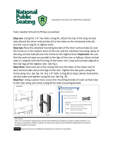
Module-to-Module Assembly . . . . . . . . . . . . . . . . . . . . . . . . . . . . . . . . . . . 26
Component Installation Requirements . . . . . . . . . . . . . . . . . . . . . . . . . . . . . . . . . . . 33
Diffuser Modules . . . . . . . . . . . . . . . . . . . . . . . . . . . . . . . . . . . . . . . . . . . . . . . . . 33
Filter Modules . . . . . . . . . . . . . . . . . . . . . . . . . . . . . . . . . . . . . . . . . . . . . . . . . . . . 33

CLCH-PRC03C-EN 5
Filter Installation . . . . . . . . . . . . . . . . . . . . . . . . . . . . . . . . . . . . . . . . . . . . . 34
Filter Placement . . . . . . . . . . . . . . . . . . . . . . . . . . . . . . . . . . . . . . . . . . . . . . . . . . 35
Fan Modules . . . . . . . . . . . . . . . . . . . . . . . . . . . . . . . . . . . . . . . . . . . . . . . . . . . . . 39
Fan Isolation . . . . . . . . . . . . . . . . . . . . . . . . . . . . . . . . . . . . . . . . . . . . . . . . 39
Removing Shipping Tie-Downs . . . . . . . . . . . . . . . . . . . . . . . . . . . . . . . . . 39
Adjusting the Isolators . . . . . . . . . . . . . . . . . . . . . . . . . . . . . . . . . . . . . . . . 40
Damper Modules . . . . . . . . . . . . . . . . . . . . . . . . . . . . . . . . . . . . . . . . . . . . . . . . . 41
Opposed-Blade and Parallel-Blade Dampers . . . . . . . . . . . . . . . . . . . . . . 42
Multizone Modules . . . . . . . . . . . . . . . . . . . . . . . . . . . . . . . . . . . . . . . . . . . . . . . . 43
Duct Connections . . . . . . . . . . . . . . . . . . . . . . . . . . . . . . . . . . . . . . . . . . . . . . . . . 44
Fan Discharge Connections . . . . . . . . . . . . . . . . . . . . . . . . . . . . . . . . . . . . 44
Damper Module Connections . . . . . . . . . . . . . . . . . . . . . . . . . . . . . . . . . . . 45
Discharge Plenum Connections . . . . . . . . . . . . . . . . . . . . . . . . . . . . . . . . . 45
Traq Damper Connections . . . . . . . . . . . . . . . . . . . . . . . . . . . . . . . . . . . . . 46
External Face-and-Bypass Connections . . . . . . . . . . . . . . . . . . . . . . . . . . 46
Other Module Connections . . . . . . . . . . . . . . . . . . . . . . . . . . . . . . . . . . . . . 48
Coil Piping and Connections . . . . . . . . . . . . . . . . . . . . . . . . . . . . . . . . . . . . . . . . . . . . 49
General Coil Piping Recommendations . . . . . . . . . . . . . . . . . . . . . . . . . . . . . . 49
Drain Pan Trapping . . . . . . . . . . . . . . . . . . . . . . . . . . . . . . . . . . . . . . . . . . . . . . . 50
Steam Coil Piping . . . . . . . . . . . . . . . . . . . . . . . . . . . . . . . . . . . . . . . . . . . . . . . . . 52
Water Coil Piping . . . . . . . . . . . . . . . . . . . . . . . . . . . . . . . . . . . . . . . . . . . . . . . . . 54
Refrigerant Coil Piping . . . . . . . . . . . . . . . . . . . . . . . . . . . . . . . . . . . . . . . . . . . . . 56
Liquid Lines . . . . . . . . . . . . . . . . . . . . . . . . . . . . . . . . . . . . . . . . . . . . . . . . . 57
Suction Lines . . . . . . . . . . . . . . . . . . . . . . . . . . . . . . . . . . . . . . . . . . . . . . . . 59
Examples of Field-Installed Evaporator Piping . . . . . . . . . . . . . . . . . . . . . . . . 60
Single-Circuit Condensing Unit: Evaporator Coil with One Distributor . 60
Single-Circuit Condensing Unit: Evaporator Coil with Two Distributors 61
Single-Circuit Condensing Unit: Evaporator Coil with Four Distributors 62
Dual-Circuit Condensing Unit: Evaporator Coil with Two Distributors) . 63
Dual-Circuit Condensing Unit: Evaporator Coil with Four Distributors . 64
Dual-Circuit Condensing Unit: Evaporator Coil with Eight Distributors . 65
Wiring . . . . . . . . . . . . . . . . . . . . . . . . . . . . . . . . . . . . . . . . . . . . . . . . . . . . . . . . . . . . . . . . 66
Controls Interface . . . . . . . . . . . . . . . . . . . . . . . . . . . . . . . . . . . . . . . . . . . . . . . . . . . . . . 69
Connecting the operator display . . . . . . . . . . . . . . . . . . . . . . . . . . . . . . . . . . . . 69
Setting up the operator display . . . . . . . . . . . . . . . . . . . . . . . . . . . . . . . . . . . . . 69
Calibrating the operator display . . . . . . . . . . . . . . . . . . . . . . . . . . . . . . . . . . . . . 69
Adjusting brightness and contrast . . . . . . . . . . . . . . . . . . . . . . . . . . . . . . . . . . . 70
Startup . . . . . . . . . . . . . . . . . . . . . . . . . . . . . . . . . . . . . . . . . . . . . . . . . . . . . . . . . . . . . . . 71
Pre-Startup Checklist . . . . . . . . . . . . . . . . . . . . . . . . . . . . . . . . . . . . . . . . . . . . . . 71
General Checks . . . . . . . . . . . . . . . . . . . . . . . . . . . . . . . . . . . . . . . . . . . . . . . . . . . 71

6 CLCH-PRC03C-EN
Fan-Related Checks . . . . . . . . . . . . . . . . . . . . . . . . . . . . . . . . . . . . . . . . . . . . . . . 72
Coil-Related Checks . . . . . . . . . . . . . . . . . . . . . . . . . . . . . . . . . . . . . . . . . . . . . . . 72
Motor-Related Checks . . . . . . . . . . . . . . . . . . . . . . . . . . . . . . . . . . . . . . . . . . . . . 73
Unit Operation . . . . . . . . . . . . . . . . . . . . . . . . . . . . . . . . . . . . . . . . . . . . . . . . . . . . 73
Calculate Motor Voltage Imbalance . . . . . . . . . . . . . . . . . . . . . . . . . . . . . . 74
Tension the Fan Belt . . . . . . . . . . . . . . . . . . . . . . . . . . . . . . . . . . . . . . . . . . 75
Determine Fan Speed . . . . . . . . . . . . . . . . . . . . . . . . . . . . . . . . . . . . . . . . . 76
Align Fan and Motor Sheaves . . . . . . . . . . . . . . . . . . . . . . . . . . . . . . . . . . 77
Check Multiple Belts . . . . . . . . . . . . . . . . . . . . . . . . . . . . . . . . . . . . . . . . . . 77
Traq™ Dampers . . . . . . . . . . . . . . . . . . . . . . . . . . . . . . . . . . . . . . . . . . . . . . . . . . 77
Fan Inlet Airflow Measuring System . . . . . . . . . . . . . . . . . . . . . . . . . . . . . . . . . 79
Wiring . . . . . . . . . . . . . . . . . . . . . . . . . . . . . . . . . . . . . . . . . . . . . . . . . . . . . . 80
Transmitter Calibration . . . . . . . . . . . . . . . . . . . . . . . . . . . . . . . . . . . . . . . . 80
Constant Factor K . . . . . . . . . . . . . . . . . . . . . . . . . . . . . . . . . . . . . . . . . . . . 80
External Insulating Requirements . . . . . . . . . . . . . . . . . . . . . . . . . . . . . . . . . . . . . . . 81
Routine Maintenance . . . . . . . . . . . . . . . . . . . . . . . . . . . . . . . . . . . . . . . . . . . . . . . . . . 82
Air Filters . . . . . . . . . . . . . . . . . . . . . . . . . . . . . . . . . . . . . . . . . . . . . . . . . . . . . . . . 83
Throwaway Filters . . . . . . . . . . . . . . . . . . . . . . . . . . . . . . . . . . . . . . . . . . . . 83
Permanent Filters . . . . . . . . . . . . . . . . . . . . . . . . . . . . . . . . . . . . . . . . . . . . 83
Cartridge or Bag Filters . . . . . . . . . . . . . . . . . . . . . . . . . . . . . . . . . . . . . . . . 83
Drain Pans . . . . . . . . . . . . . . . . . . . . . . . . . . . . . . . . . . . . . . . . . . . . . . . . . . . . . . . 84
Fans . . . . . . . . . . . . . . . . . . . . . . . . . . . . . . . . . . . . . . . . . . . . . . . . . . . . . . . . . . . . . 85
Inspecting and Cleaning Fans . . . . . . . . . . . . . . . . . . . . . . . . . . . . . . . . . . 85
Bearing Set Screw Alignment . . . . . . . . . . . . . . . . . . . . . . . . . . . . . . . . . . 85
Fan Bearing Lubrication . . . . . . . . . . . . . . . . . . . . . . . . . . . . . . . . . . . . . . . 86
Motor Bearing Lubrication . . . . . . . . . . . . . . . . . . . . . . . . . . . . . . . . . . . . . 87
Fan Motor Inspection . . . . . . . . . . . . . . . . . . . . . . . . . . . . . . . . . . . . . . . . . 87
Coils . . . . . . . . . . . . . . . . . . . . . . . . . . . . . . . . . . . . . . . . . . . . . . . . . . . . . . . . . . . . 87
Steam and Water Coils . . . . . . . . . . . . . . . . . . . . . . . . . . . . . . . . . . . . . . . . 87
Type K Cooling Coils . . . . . . . . . . . . . . . . . . . . . . . . . . . . . . . . . . . . . . . . . . 88
Refrigerant Coils . . . . . . . . . . . . . . . . . . . . . . . . . . . . . . . . . . . . . . . . . . . . . 88
Coil Winterization . . . . . . . . . . . . . . . . . . . . . . . . . . . . . . . . . . . . . . . . . . . . 89
Type UW, UU, W, P2, P4, P8, WD, 5D, and 5W Coils . . . . . . . . . . . . . . . . 89
Type K Coils . . . . . . . . . . . . . . . . . . . . . . . . . . . . . . . . . . . . . . . . . . . . . . . . . 90
Moisture Purge Cycle . . . . . . . . . . . . . . . . . . . . . . . . . . . . . . . . . . . . . . . . . 90
Internal Insulation . . . . . . . . . . . . . . . . . . . . . . . . . . . . . . . . . . . . . . . . . . . . 90
Ultraviolet (UV) Light Maintenance . . . . . . . . . . . . . . . . . . . . . . . . . . . . . . . . . . 92
Cleaning the Bulbs . . . . . . . . . . . . . . . . . . . . . . . . . . . . . . . . . . . . . . . . . . . 92
Replacing the Bulbs . . . . . . . . . . . . . . . . . . . . . . . . . . . . . . . . . . . . . . . . . . 93
Disposal of Bulbs . . . . . . . . . . . . . . . . . . . . . . . . . . . . . . . . . . . . . . . . . . . . . 93
Troubleshooting . . . . . . . . . . . . . . . . . . . . . . . . . . . . . . . . . . . . . . . . . . . . . . . . . . . . . . . 94

CLCH-PRC03C-EN 7
General Information
Operating Environment
When considering the placement of the air handler, it is important to consider the operating
environment. The acceptable ambient temperature range for unit operation is -40ºF to 140ºF (-40ºC
to 60ºC).
For heating applications, a special motor may be required to withstand the higher temperatures.
Motors with Class B insulation are acceptable for ambient temperatures up to 104º F, while motors
with Class F insulation can withstand ambient temperatures to +140º F (60º C).
Note: The customer should provide adequate freeze protection for the coils. See the “Coil
Winterization” section on page 89 for more information.
Unit Description
The M-Series Climate Changer™ air handler is a highly flexible, customizable, cataloged air
handler that can meet most commercial, industrial and institutional applications. With its modular,
“building-block” construction, the M-Series air handler can be tailored to meet specific job
requirements for new or existing buildings. A wide range of standard and custom-engineered
modules can be arranged and stacked in any number of configurations to address application and
space requirements.
The wide array of available components is key to fine-tuning the performance of the M-Series air
handler. The broad spectrum of fan coil, filter and control options allows you to optimize the
performance and efficiency of your air handler.
While several air-handling manufacturers offer some custom features, most find it difficult to
incorporate those features into their standard cataloged unit, which leads to increased costs and
extended lead times. Trane has engineered many custom solutions - with tested performance data
- for the M-Series air handler, without the cost and lead times associated with full-blown custom
units.
Trane continues to develop new options for M-Series air handlers, so that you remain firmly in
control of performance and cost on every design project.
For more information, refer to the following documents, available from your local Trane sales
engineer:
• M-Series Climate Changer™ Air Handlers catalog, CLCH-PRC003-EN
• Gas Heat for M-Series and T-Series Climate Changer™Air Handlers installation manual,
CLCH-SVX04C-EN
• Energy Wheels for M-Series Climate Changer™ Air Handlers installation manual,
CLCH-SVX02C-EN
• LJ Wing Coils - installation manual available from www.ljwing.com
–IOMIFB-5
–IOMVIFB-5
• Humidifiers - installation manual available from www.armstrong-intl.com
– Armstrong Bulletin No. 560-G

8 CLCH-PRC03C-EN
General Information
Wiring
WARNING
Grounding Required!
All field-installed wiring must be completed by qualified personnel. All field-installed wiring
must comply with NEC and applicable local codes. Failure to follow these instructions could
result in death or serious injuries.
There are no penetrations into the M-Series air handler for any field-provided wiring or device.
Before installation, consider overall unit serviceability and accessibility before mounting, running
wires (power), making cabinet penetrations, or mounting any components to the cabinet.
Wiring to air-handling unit must be provided by the installer and must comply with all national and
local electrical codes. The fan motor nameplate includes a wiring diagram. If there are any
questions concerning the wiring of the motor, write down the information on the motor nameplate
and contact your local Trane sales office.
Controls
Factory-Mounted Controls
Small items that cannot be factory mounted will ship inside the control enclosures. Larger items
may ship inside the fan module.
Note: All control valves ship directly to the “ship-to address” from the vendor unless another
address is given on the Trane sales order.
All factory-mounted control systems (controls that are factory-wired to a unit controller or
termination strip) ordered without starters or variable-frequency drives (VFDs) are provided with
line to 24 Vac control transformers mounted and wired in the auxiliary control panel. The customer
must provide 120 Vac control power, 50/60 Hz, typically 3 amps for unit sizes 3 to 57 and 5 amps
for unit sizes 66 to 120. A dedicated 15-amp circuit is recommended.
Factory-mounted control systems ordered with factory-mounted starters or VFDs are supplied with
line to 24 Vac control transformers. No additional power wiring is required.
For a more in-depth understanding of controls, refer to the following manuals:
• For programmable MP580 controllers, CNT-SVP01A-EN
• For hardware installation, CNT-SVN01A-EN
• For Danfoss VFD, TR1-SVX10A-EN
Pre-Packaged Solutions
If the air handler has been selected using one of Trane’s pre-packaged solutions options for
controls, there are a number of resources available to aid in commissioning and start-up of the unit.
These resources include commissioning sheets, graphics and technical application notes. The
technical application notes include the control sequencing, Trane Graphic Programming (TGP) and
Rover set-up files for the specific unit selected. These resources are available through your local
Trane sales office.

CLCH-SVX03C-EN 9
Pre-Installation Requirements
M-Series Climate Changer air handlers can ship as individual modules, module subassemblies, or
a complete air handler. Unit sizes 3 to 57 may have a base rail (also called an external support kit).
Unit sizes 66 to 120 ship on an integral base rail. Modules shipped without a base rail are securely
fastened to a wooden skid using 4-inch mounting legs for ease of handling. No skid is provided on
units with base rails. Trane recommends leaving units and accessories, such as filter boxes and
control devices, in their shipping packages/skids for protection and ease of handling until
installation.
M-Series air handler sizes 3 to 57 ship in subassemblies if the total length of the unit exceeds
98 inches, or if the total weight exceeds the limits as calculated using Tables 2-5 on pages 14-17 and
Table 7 on page 18. If an optional factory base rail and standard factory shipping splits were
ordered, each subassembly will ship on its own base rail as standard. If an optional factory base
rail and minimum factory shipping splits were ordered, the base rail will ship separate from each
subassembly.
M-Series air handler sizes 66 to 120 ship in subassemblies if the total length of the unit exceeds
102 inches, or if the total weight exceeds 4,300 pounds. These unit sizes have an integral base rail
on each module.
Receiving Checklist
Upon receipt of the air-handling unit, prior to unloading, visually check the components for any
damage that may have occurred during shipment. Conduct a thorough inspection immediately
before accepting the shipment.
Note: Delivery cannot be refused. Trane is not responsible for shipping damage.
1. Remove any shrink wrap material that may have been used during shipping. Cut all banding
loose from the skids (if applicable). Do not remove the unit from the skid.
NOTICE
Equipment Damage!
Keep skid in place until unit is ready to set. Do not move the unit or subassembly without the
skid in place as shipped from the factory. Premature skid removal may result in equipment
damage.
2. Check all access doors to confirm the latches and hinges are not damaged.
3. Inspect the interior of each module for any internal damage.
Note: Concealed damage must be reported within 15 days of receipt.
4. Inspect the coils for damage to the fin surface and/or coil connections.
5. If the unit was ordered with factory-mounted controls, locate all sensors.
Note: Items that cannot be factory-mounted should ship inside the control enclosures or should
be packaged inside the fan module or mixing box module.
6. Check all control devices attached to the unit exterior and confirm they are not damaged.
7. Manually rotate the fan wheel to ensure free movement of the shaft, bearings, and drive.
8. Inspect the fan housing for any foreign objects.
9. If the unit shipped in subassemblies, locate the assembly hardware, which should be packaged
and shipped inside the fan module or the mixing box module.

10 CLCH-SVX03C-EN
Pre-Installation Requirements
Assembly Hardware
Trane air handlers ship with all necessary assembly hardware and gasket material. This hardware
is packaged in either a clear plastic envelope or cardboard box and can be found inside the fan,
mixing box, or access module. If there is not enough space inside the module, a crate or pallet will
be loaded onto the bed of the truck. Check the Parts List on the Field Assembly drawing against the
contents of the crate. Do not proceed with unit assembly until verification that all materials are
present. Sometimes it is necessary to use more than one section to ship hardware. Please check
all sections thoroughly before contacting your local Trane sales engineer to report missing
hardware.
Resolving Shipping Damage
Trane air handlers ship free on board (FOB) ship dock, meaning that the unit belongs to the
customer the moment the delivery truck leaves the factory shipping dock. If damage has occurred
to the unit during shipment, follow these instructions:
Note: Trane is not responsible for shipping damage.
1. Make specific notation, describing the damage, on the freight bill. Take photos of the damaged
material, if possible.
2. Report all claims of shipping damage to the delivering carrier immediately and coordinate
carrier inspection, if necessary.
Note: : Do not attempt to repair the unit without consulting the delivering carrier.
3. Notify your Trane sales representative of the damage and arrange for repair.
Note: Do not attempt to repair the unit without consulting your Trane sales representative.
4. Keep the damaged material in the same location as it was received.
Note: It is the receiver's responsibility to provide reasonable evidence that concealed damage was
not incurred after delivery.
Job Site Storage Recommendations
M-Series units and/or field-installed accessories that must be stored for a period of time before
installations must be protected from the elements. A controlled indoor environment is
recommended for proper storage.
Note: The warranty does not cover damage to the unit or controls due to negligence during
storage.
General Storage
The unit controller and all other electrical/electronic components should be stored in conditions of
-20ºF to 120°F and 5 to 95 percent relative humidity, non-condensing. Electrical components are
not moisture-tolerant. Factory protective coverings, such as shrink-wrap material, should be
removed within 48 hours of receiving the unit, and prior to storage.

CLCH-SVX03C-EN 11
Pre-Installation Requirements
Long-Term Storage
While the unit is in storage:
• Every two weeks, rotate the fan and motor shaft 30 revolutions by hand. Check for free rotation.
• Every six months, check fan shaft bearings and grease lines. Add grease using a manual grease
gun following the lubrications recommendations in the “Fan Bearing Lubrication” section on
page 86.
Check the motor lubrication; remove and clean grease plugs and check for the presence of moisture
in the grease. If moisture is present, remove the motor and send it to an authorized repair shop for
bearing inspection/replacement. If no moisture if present, refer to the motor manufacturer’s
lubrication recommendation for proper lubrication.
Outdoor Storage Considerations
Outdoor storage is not recommended; however, when outdoor storage is necessary, several things
must be done to prevent damage:
Note: Keep the equipment in the original shipping container for protection and ease of handling.
1. Remove any shrink-wrap material within 48 hours of receiving the unit.
2. Select a well-drained area, preferably a concrete pad or blacktop surface.
3. Place the unit on a dry surface or raised off the ground to assure adequate air circulation
beneath the unit and to assure no portion of the unit will contact standing water at any time.
4. Loosen the belt tension on the drive belts.
5. Cover the unit securely with a canvas tarp.
NOTICE
Corrosion!
Use only canvas tarps to cover air handlers. Plastic tarps can cause condensation to form in and
on the equipment, which may result in corrosion damage or wet storage stains.
6. Allow proper clearance around the unit to perform periodic inspection and maintenance of the
equipment while in storage (see Figure 1 and Table 1 on page 13).
7. Do not stack units.
8. Do not pile other material on the unit.

12 CLCH-SVX03C-EN
Pre-Installation Requirements
Preparing the Unit Site
WARNING
Live Electrical Components!
During installation, testing, servicing and troubleshooting of this product, it may be necessary
to work with live electrical components. Have a qualified licensed electrician or other individual
who has been properly trained in handling live electrical components perform these tasks.
Failure to follow all electrical safety precautions when exposed to live electrical components
could result in death or serious injury.
1. Ensure the installation site can support the total weight of the unit (see the “Dimensions and
Weights” section on page 13 for approximate module weights; refer to the unit submittals for
actual module weights).
2. Allow sufficient space for the recommended service access (see “Service Clearances on
page 13).
3. Ensure there is adequate height for condensate drain requirements (see the “Drain Pan
Trapping” section on page 50).
NOTICE
Microbial Growth!
The floor or foundation must be level and the condensate drain at the proper height for proper
coil drainage and condensate flow. Standing water and wet surfaces inside the equipment can
become an amplification site for microbial growth (mold), which may cause odors and damage
to the equipment and building materials.
4. Confirm the foundation of the mounting platform is level and large enough to include the unit
dimensions (refer to the unit submittals for specific dimensions).
5. Provide adequate lighting for maintenance personnel to perform maintenance duties.
6. Provide permanent power outlets in close proximity to the unit for installation and
maintenance.
7. Unless the unit is ordered with a factory-mounted/wired starter or variable-frequency drive, the
customer must provide 120 Vac power to the unit controller, 50/60 Hz, typically 3 amps for unit
sizes 3 to 57 and 5 amps for unit sizes 66 to 120. A dedicated 15-amp circuit is recommended.
8. Wiring to the air handler must be provided by the installer and must comply with all national
and local electrical codes.
9. If a factory-provided base rail was not ordered to ceiling suspend M-Series unit sizes 3 to 57, the
installer/contractor must provide a ceiling-suspended mounting frame designed to support the
length, width, and weight of the entire air-handling unit. See the “Ceiling Suspension” section
on page 25 for more information.

CLCH-PRC03C-EN 13
Dimensions and Weights
Service Clearances
Figure 1. Service Clearance
Table 1. Service clearances (inches)
Clearance Items 3 6 8 10 12 14 17 21 25 30 35 40 50 57 66 80 100 120
A (filter) 484848484848484848484848484852565858
B (coil) 48 60 64 75 79 83 89 91 93 106 110 123 134 134 150 150 165 165
C (fan) 48484851545861606666657077779391101101
D (starter or VFD) 60 60 60 60 60 60 60 60 60 60 60 60 60 60 60 60 60 60
Note: At a minimum, the above clearance dimensions are recommended on one side of the unit for regular service and maintenance. Refer to as-built
submittal for locations of items such as filter access doors, coil, piping connections, motor locations, etc. Sufficient clearance must be provided on
all sides of unit for removal of panels or module-to-module attachment brackets. Clearance for starters, VFDs, or other high-voltage devices must
be provided per NEC requirements.

14 CLCH-PRC03C-EN
Dimensions and Weights
Single-Wall Construction Weights
Note: For specific dimensional and weight information, refer to the unit submittals. The dimensions and weights in this manual
are approximate. Trane has a policy of continuous product and product data improvement and reserves the right to
change design and specifications without notice.
Table 2. Module weights (pounds) per unit size for single-wall construction unit sizes 3-25
Module Type 3 6 8 10 12 14 17 21 25
Intake....... n/a n/a n/a n/a n/a n/a n/a n/a n/a
Mixing box with filter 156 195 237 271 312 339 379 429 498
Mixing box without filter 124 174 212 241 278 289 323 366 433
Traq™ mixing box 136 168 206 236 268 301 332 426 427
Blender module 106 141 153 174 232 251 226 250 292
Filter, angled 106 139 141 161 176 198 217 235 248
Filter, short bag or cartridge 108 140 141 160 177 206 227 233 250
Filter, flat 54 67 76 84 98 104 113 124 130
Filter, flat combination 79 100 114 127 155 166 180 192 203
Filter, flat, open-return 11 16 19 22 34 39 43 44 45
Filter, HEPA n/a n/a n/a n/a n/a n/a n/a n/a n/a
Filter, long bag-30 in. 128 171 200 192 227 264 326 344 398
Blank/inspection, small 59 72 80 89 97 102 110 118 126
Blank/access, medium 72 85 94 106 115 121 131 141 149
Blank/access, ext-medium 82 97 108 122 132 139 150 161 171
Blank/access, med-large n/a n/a 134 151 164 171 185 198 210
Blank/access/turning, large 102 134 164 191 207 215 232 253 297
Blank/access/turning, ex-large 111 148 174 163 197 211 244 296 345
Face-and-bypass, external 101 136 163 196 228 242 283 315 349
Face-and-bypass, internal 78 107 131 155 195 185 212 259 291
Face damper 83 109 133 158 188 199 236 267 299
Coil, small w/2-row UW n/a n/a n/a n/a n/a n/a n/a n/a n/a
Coil,.medium w/8-row UW n/a n/a n/a n/a n/a n/a n/a n/a n/a
Coil, ext-med w/8-row UW n/a n/a n/a n/a n/a n/a n/a n/a n/a
Coil, med-large w/10-row W n/a n/a n/a n/a n/a n/a n/a n/a n/a
Coil, large or vert w/10-row W n/a n/a n/a n/a n/a n/a n/a n/a n/a
Coil, electric heat n/a n/a n/a n/a n/a n/a n/a n/a n/a
Coil, integral face-and-bypass n/a n/a n/a n/a n/a n/a n/a n/a n/a
Coil, multizone/double-duct n/a n/a n/a n/a n/a n/a n/a n/a n/a
Humidifier n/a n/a n/a n/a n/a n/a n/a n/a n/a
Moisture eliminator n/a n/a n/a n/a n/a n/a n/a n/a n/a
FC fan
1
292 371 461 507 567 629 786 912 1042
AF fan
1
323 472 494 629 717 742 926 1167 1226
BC fan
1
342 n/a n/a n/a n/a n/a n/a n/a n/a
Plenum fan
1
323 410 447 518 638 645 710 1119 1292
Diffuser 68 86 97 114 126 180 197 212 225
Discharge plenum, horizontal n/a n/a n/a n/a n/a n/a n/a n/a n/a
Discharge plenum, vertical n/a n/a n/a n/a n/a n/a n/a n/a n/a
Silencer, 3 ft. n/a n/a n/a n/a n/a n/a n/a n/a n/a
Silencer, 5 ft. n/a n/a n/a n/a n/a n/a n/a n/a n/a
Energy wheel
2
n/a n/a n/a n/a n/a n/a n/a n/a n/a
Gas heat
3
n/a n/a n/a n/a n/a n/a n/a n/a n/a
Note: (1) Fan module weights include the heaviest fan with the largest ODP motor available. (2) The weight of the energy wheel module is with the largest
wheel available for each unit size. The weights include all dampers and filter rack, they do not include end devices, control wiring or a starter. (3)
Weights of the gas heat modules are with the largest capacity burner. Refer to the M-Series Gas Heat Quick Select (CLCH-SLB004-EN) or the TOPSS
selection program for detailed dimensions.

CLCH-PRC03C-EN 15
Dimensions and Weights
Note: For specific dimensional and weight information, refer to the unit submittals. The dimensions and weights in this manual
are approximate. Trane has a policy of continuous product and product data improvement and reserves the right to
change design and specifications without notice.
Table 3. Module weights (pounds) per unit size for single-wall construction unit sizes 30-120
Module Type 30 35 40 50 57 66 80 100 120
Intake....... n/a n/a n/a n/a n/a n/a n/a n/a n/a
Mixing box with filter 558 780 861 1010 1144 1430 1616 1915 2156
Mixing box without filter 485 699 771 904 997 1251 1392 1630 1825
Traq™ mixing box 565 684 747 873 959 1281 1433 1661 1867
Blender module 325 402 448 516 565 647 725 853 1273
Filter, angled 271 325 349 399 466 698 755 859 960
Filter, short bag or cartridge 274 380 423 491 554 764 830 935 1054
Filter, flat 142 195 210 274 310 497 537 612 688
Filter, flat combination 224 251 274 313 355 552 601 691 781
Filter, flat, open-return 53 68 78 99 120 146 169 210 247
Filter, HEPA n/a n/a n/a n/a n/a n/a n/a n/a n/a
Filter, long bag-30 in. 434 472 517 588 646 937 1052 1229 1373
Blank/inspection, small 136 177 189 240 257 455 464 506 567
Blank/access, medium 162 205 220 n/a n/a n/a n/a n/a n/a
Blank/access, ext-medium 186 235 252 284 303 476 487 528 586
Blank/access, med-large 228 316 340 381 407 610 624 677 752
Blank/access/turning, large 325 448 480 538 574 869 945 1113 1230
Blank/access/turning, ex-large 371 542 575 668 707 893 1007 1135 1229
Face-and-bypass, external 399 444 488 606 660 982 1101 1304 1519
Face-and-bypass, internal 332 409 446 586 662 910 997 1180 1363
Face damper 340 372 408 517 570 825 945 1128 1311
Coil, small w/2-row UW n/a n/a n/a n/a n/a n/a n/a n/a n/a
Coil,.medium w/8-row UW n/a n/a n/a n/a n/a n/a n/a n/a n/a
Coil, ext-med w/8-row UW n/a n/a n/a n/a n/a n/a n/a n/a n/a
Coil, med-large w/10-row W n/a n/a n/a n/a n/a n/a n/a n/a n/a
Coil, large or vert w/10-row W n/a n/a n/a n/a n/a n/a n/a n/a n/a
Coil, electric heat n/a n/a n/a n/a n/a n/a n/a n/a n/a
Coil, integral face-and-bypass n/a n/a n/a n/a n/a n/a n/a n/a n/a
Coil, multizone/double-duct n/a n/a n/a n/a n/a n/a n/a n/a n/a
Humidifier n/a n/a n/a n/a n/a n/a n/a n/a n/a
Moisture eliminator n/a n/a n/a n/a n/a n/a n/a n/a n/a
FC fan
1
1152 1785 1937 2543 2582 3923 4130 4455 4587
AF fan
1
1647 2269 2156 2957 2997 3662 4349 5189 5732
BC fan
1
n/a n/a n/a n/a n/a n/a n/a n/a n/a
Plenum fan
1
1423 1671 1838 2485 2524 3228 4077 4665 5066
Diffuser 249 322 350 438 477 927 1037 1230 1377
Discharge plenum, horizontal n/a n/a n/a n/a n/a n/a n/a n/a n/a
Discharge plenum, vertical n/a n/a n/a n/a n/a n/a n/a n/a n/a
Silencer, 3 ft. n/a n/a n/a n/a n/a n/a n/a n/a n/a
Silencer, 5 ft. n/a n/a n/a n/a n/a n/a n/a n/a n/a
Energy wheel
2
n/a n/a n/a n/a n/a n/a n/a n/a n/a
Gas heat
3
n/a n/a n/a n/a n/a n/a n/a n/a n/a
Note: (1) Fan module weights include the heaviest fan with the largest ODP motor available. (2) The weight of the energy wheel module is with the largest
wheel available for each unit size. The weights include all dampers and filter rack, they do not include end devices, control wiring or a starter. (3)
Weights of the gas heat modules are with the largest capacity burner. Refer to the M-Series Gas Heat Quick Select (CLCH-SLB004-EN) or the TOPSS
selection program for detailed dimensions.

16 CLCH-PRC03C-EN
Dimensions and Weights
Double-Wall Construction Weights
Note: For specific dimensional and weight information, refer to the unit submittals. The dimensions and weights in this manual
are approximate. Trane has a policy of continuous product and product data improvement and reserves the right to
change design and specifications without notice.
Table 4. Module weights (pounds) per unit size for double-wall construction for unit sizes 3-25
Unit size 3 6 8 10 12 14 17 21 25
Intake....... 134 183 221 263 307 332 380 432 485
Mixing box with filter 181 223 277 319 367 390 437 495 577
Mixing box without filter 142 202 253 288 332 341 381 432 512
Traq™ mixing box 159 191 239 275 309 341 376 512 487
Blender module 129 174 193 221 297 322 282 309 366
Filter, angled 126 168 169 194 212 235 258 278 294
Filter, short bag or cartridge 128 170 168 193 213 243 268 276 295
Filter, flat 62 78 89 99 115 121 131 143 151
Filter, flat combination 91 116 131 148 178 190 207 219 232
Filter, flat, open-return 11 16 19 22 34 39 43 44 45
Filter, HEPA 213 296 363 400 450 493 608 710 840
Filter, long bag-30 in. 158 218 257 241 292 334 408 443 516
Blank/inspection, small 65 79 88 99 107 112 121 131 139
Blank/access, medium 80 95 105 119 129 136 147 158 168
Blank/access, ext-medium 92 109 122 137 150 157 170 182 193
Blank/access, med-large n/a n/a 151 171 186 195 210 225 238
Blank/access/turning, large 115 152 190 221 240 247 267 290 344
Blank/access/turning, ex-large 141 195 231 212 261 282 326 395 463
Face-and-bypass, external 117 156 185 221 256 271 315 350 385
Face-and-bypass, internal 94 127 153 181 213 224 244 293 328
Face damper 99 129 156 184 216 228 268 301 335
Coil, small w/2-row UW 108 139 159 186 215 232 256 296 329
Coil,.medium w/8-row UW 174 238 281 339 405 447 505 597 678
Coil, ext-med w/8-row UW 187 253 299 359 426 469 532 627 709
Coil, med-large w/10-row W n/a n/a 499 602 731 798 925 1027 1168
Coil, large or vert w/10-row W 293 432 543 656 790 859 992 1098 1294
Coil, electric heat 201 309 372 440 483 518 583 634 758
Coil, integral face-and-bypass 312 398 500 559 611 677 788 820 1019
Coil, multizone/double-duct n/a 733 818 1031 1303 1384 1511 1719 1897
Humidifier 198 256 281 317 363 386 439 462 512
Moisture eliminator 120 166 201 240 281 304 348 396 446
FC fan
1
322 418 518 557 632 699 868 1012 1160
AF fan
1
353 519 551 678 782 813 1008 1266 1344
BC fan
1
371 n/a n/a n/a n/a n/a n/a n/a n/a
Plenum fan
1
353 456 502 567 700 713 791 1218 1410
Diffuser 84 106 119 140 154 210 229 246 262
Discharge plenum, horizontal 133 180 223 263 292 305 336 366 431
Discharge plenum, vertical 148 205 249 251 279 296 327 357 428
Silencer, 3 ft. 354 431 468 528 604 639 705 757 803
Silencer, 5 ft. 534 648 707 794 966 1009 1115 1197 1591
Energy wheel
2
417 555 617 837 1051 1165 1311 1399 1778
Gas heat
3
n/a 1170 1226 1407 1437 1491 1806 2482 2450
Note: (1) Fan module weights include the heaviest fan with the largest ODP motor available. (2) The weight of the energy wheel module is with the largest
wheel available for each unit size. The weights include all dampers and filter rack, they do not include end devices, control wiring or a starter. (3)
Weights of the gas heat modules are with the largest capacity burner. Refer to the M-Series Gas Heat Quick Select (CLCH-SLB004-EN) or the TOPSS
selection program for detailed dimensions.

CLCH-PRC03C-EN 17
Dimensions and Weights
Note: For specific dimensional and weight information, refer to the unit submittals. The dimensions and weights in this manual
are approximate. Trane has a policy of continuous product and product data improvement and reserves the right to
change design and specifications without notice.
Table 5. Module weights (pounds) per unit size for double-wall construction for unit sizes 30-120
Unit size 30 35 40 50 57 66 80 100 120
Intake....... 553 670 747 973 1096 1513 1699 2023 2326
Mixing box with filter 646 890 982 1158 1290 1589 1798 2133 2387
Mixing box without filter 573 809 891 1051 1143 1410 1575 1847 2056
Traq™ mixing box 676 770 840 978 1056 1743 1936 2161 2328
Blender module 407 507 564 646 700 801 902 1071 1665
Filter, angled 321 390 421 480 549 791 852 967 1082
Filter, short bag or cartridge 324 446 495 571 637 857 927 1042 1175
Filter, flat 165 221 238 314 352 543 585 666 748
Filter, flat combination 257 287 313 353 397 598 649 745 841
Filter, flat, open-return 53 68 78 99 120 146 169 210 247
Filter, HEPA 972 1028 1150 1374 1467 1735 1969 2383 2740
Filter, long bag-30 in. 565 586 642 728 793 1104 1244 1464 1635
Blank/inspection, small 150 193 207 265 283 484 495 541 605
Blank/access, medium 182 228 244 n/a n/a n/a n/a n/a n/a
Blank/access, ext-medium 210 262 282 318 339 516 529 575 638
Blank/access, med-large 259 357 384 431 460 669 686 746 828
Blank/access/turning, large 376 514 551 619 659 965 1058 1252 1384
Blank/access/turning, ex-large 502 697 744 873 926 1197 1361 1548 1686
Face-and-bypass, external 439 500 548 674 732 1061 1186 1398 1623
Face-and-bypass, internal 372 453 495 654 734 990 1082 1274 1467
Face damper 381 427 468 584 642 905 1030 1223 1415
Coil, small w/2-row UW 370 444 483 625 693 899 1008 1169 1333
Coil,.medium w/8-row UW 782 921 1025 n/a n/a n/a n/a n/a n/a
Coil, ext-med w/8-row UW 816 958 1065 1317 1488 1804 2092 2534 2721
Coil, med-large w/10-row W 1362 1630 1827 2331 2697 3220 3715 4511 5287
Coil, large or vert w/10-row W 1499 1835 2045 2573 2952 n/a n/a n/a n/a
Coil, electric heat 836 1056 1169 1434 1611 2261 n/a n/a n/a
Coil, integral face-and-bypass 1064 1161 1188 1691 1715 1901 2014 2162 2371
Coil, multizone/double-duct 2139 2718 2993 3818 n/a n/a n/a n/a n/a
Humidifier 565 743 810 1039 1076 1511 1617 1780 1898
Moisture eliminator 510 611 683 885 999 1317 1483 1779 2061
FC fan
1
1282 1941 2106 2747 2800 4227 4484 4868 5044
AF fan
1
1804 2424 2325 3162 3216 4378 5137 6014 6629
BC fan
1
n/a n/a n/a n/a n/a n/a n/a n/a n/a
Plenum fan
1
1554 1826 2007 2689 2742 3532 4431 5077 5523
Diffuser 289 366 398 506 549 1120 1263 1509 1684
Discharge plenum, horizontal 480 674 731 850 926 1286 1432 1713 1919
Discharge plenum, vertical 475 633 689 801 801 n/a n/a n/a n/a
Silencer, 3 ft. 971 1047 1130 1390 1657 1890 2034 2499 2891
Silencer, 5 ft. 1606 1730 1860 2218 2604 2920 3155 3911 4516
Energy wheel
2
1979 2325 2634 3079 n/a n/a n/a n/a n/a
Gas heat
3
2441 3133 3222 3854 3949 4491 4750 4508 4646
Note: (1) Fan module weights include the heaviest fan with the largest ODP motor available. (2) The weight of the energy wheel module is with the largest
wheel available for each unit size. The weights include all dampers and filter rack, they do not include end devices, control wiring or a starter. (3)
Weights of the gas heat modules are with the largest capacity burner. Refer to the M-Series Gas Heat Quick Select (CLCH-SLB004-EN) or the TOPSS
selection program for detailed dimensions.

18 CLCH-PRC03C-EN
Dimensions and Weights
Single-Piece Shipment Limitations
The specifications provided in Tabl e 6 indicate the maximum values for a single-piece shipment.
If either the maximum weight or maximum length is exceeded, the air handler will ship in multiple
pieces.
Note: These limits are based on a four-point lift.
Base Rail Weight Calculations
To determine the weight of the base rail for each shipping split, use the following equation and the
weight factors provided in Tab le 7:
Weight = (A × length) + B
Note: When an M-Series unit ships in multiple pieces, a base rail may be provided for each piece
(if ordered). In these instances, the base rail weight must be calculated for each piece.
M-Series unit sizes 66 to 120 have integral base rails; module weights for these module sizes
include the base rail.
Table 6. Shipping length and weight limitations for single-piece shipments
Unit Size
Maximum Unit
Weight (lb.)
Baserail Unit
Maximum Unit Length (in)
Non-Baserail Unit Maximum
Unit Length (in)
3–30 <2,500 98 96
35 <3,900 98 96
40 <4,300 98 96
50–57 <5,100 98 96
66-120 <4300-6000 102 n/a
Table 7. Base rail weight calculation factors
Variable
Weight Factors per Unit Size
3 6 8 10 12 14 17 21 25 30 35 40 50 57
A 3.7 3.7 3.7 3.7 3.7 3.7 3.7 3.7 3.7 3.7 3.7 3.7 3.7 3.7
B 23 29 30 36 37 39 42 43 43 49 51 57 62 62

CLCH-PRC03C-EN 19
Dimensions and Weights
Motor Weights
Fan weights provided in this manual include the heaviest ODP (open drip-proof) motor.
Approximate weights below are based on A.O. Smith brand motors.
Starter/VFD Weights
Fan weights do not include starter/VFD weights. The table below gives approximate starter/VFD
weights.
Table 8. Approximate motor weights
Motor
Type Voltage
Horsepower
1/6 1/4 1/3 1/2 1 1-1/2 2 3 5 7-1/2 10 15 20 25 30 40 50 60 75 100 125
Energy
efficient
ODP
(EEOP)
115s 12 14 16 18 - - - - - - -----------
230s - - - - - - - - - - - - - - - - - - - - -
200/3 - - - - 34 43 43 80 78 106 119 170 210 240 284 631 404 772 838 1091 -
230/460/3 - - - - 36 42 42 64 76 110 132 164 210 240 278 631 360 - - - -
575/3 - - - - 37 48 50 70 78 106 119 170 212 240 284 631 440 - - - -
Energy
efficient
TEFC
(EETC)
200/3 - - - - 60 60 65 81 89 142 154 250 290 358 - 639 705 794 860 1224
230/460/3 - - - - 60 60 65 84 90 140 138 252 283 356 436 661 705 794 860 1224 1562
575/3 - - - - 60 60 65 81 89 142 154 250 287 358 436 661 705 - - - -
NEMA
Premiu
m ODP
(HEOP)
200/3 - - - - - - - 83 94 141 126 220 250 310 300 639 720 - - - -
230/460/3 - - - - - - - 87 94 118 126 217 250 309 300 676 616 - - - -
575/3 - - - - - - - 87 94 141 124 220 250 310 306 676 720 794 860 1224 -
NEMA
Premiu
m TEFC
(HETC)
200/3 - - - - - - - 92 99 158 200 259 290 358 - - - - - - -
230/460/3 - - - - - - - 92 99 158 175 275 308 418 424 750 740 - - - -
575/3 - - - - 68 56 66 92 99 158 200 290 290 358 436 750 686 799 904 - -
Note: Approximate motor weights in pounds. Motor manufacturers vary and this data may change without notification.
Table 9. Approximate starter and VFD weights
Horsepower
Weights (lb.) per Horsepower
1 1.5 2 3 5 7.5 10 15 20 25 30 40 50 60 75 100 125
Starter 6565656565656565659797979797979797
VFD
1
75 75 75 75 75 180 180 180 180 260 260 260 260 260 260 260 n/a
Note: These weights represent the largest available starter/VFD

20 CLCH-SVX03C-EN
Installation - Mechanical
Lifting and Rigging
WARNING
Heavy Objects!
Do not use cables (chains or slings) except as shown. Each of the cables (chains or slings) used
to lift the unit must be capable of supporting the entire weight of the unit. Lifting cables (chains
or slings) may not be of the same length. Adjust as necessary for even unit lift. Other lifting
arrangements may cause equipment or property-only damage. Failure to properly lift unit could
result in death or serious injury.
WARNING
Heavy Objects!
Always place, assemble, and suspend modules/subassemblies one at a time. Do not lift units in
windy conditions. Do not raise units overhead wit personnel below unit. Failure to follow these
instructions could result in death, serious injury, or equipment damage.
WARNING
Improper Unit Lift!
Test lift unit approximately 24 inches to verify proper center of gravity lift point. To avoid
dropping of unit, reposition lifting point if unit is not level. Failure to properly lift unit could
result in death or serious injury or possible equipment or property-only damage.
NOTICE
Equipment Damage!
Keep skid in place until unit is ready to set. Do not move unit or subassembly without the skid in
place as shipped from the factory. Premature skid removal may result in equipment damage.
Before preparing the unit for lifting, estimate the approximate center of gravity for lifting safety.
Because of placement of internal components, the unit weight may be unevenly distributed, with
more weight in the coil and fan areas. Approximate unit weights are provided in the “Dimensions
and Weights” section on page 13. Refer to the unit submittals for actual module weights. Test the
unit for proper balance before lifting.
When hoisting the unit into position, use the proper rigging method, such as straps, slings,
spreader bars, or lifting lugs for protection and safety.
• For unit sizes 3 to 57 without base rails, use spreader bars and slings to rig units and
subassemblies as shown in Figure 2.
• For unit sizes 3 to 57 with base rails, use spreader bars and slings to rig units and subassemblies
as shown in Figure 3.
• For unit sizes 66 to 120, use spreader bars in conjunction with shackles attached at the base rail
lifting lugs to rig units or subassemblies as shown in Figure 4.
/