Page is loading ...


Features and benets
2
Heating, cooling and energy storage in one!
• Up to 50% lower energy consumption
• Passive, free heat and cold storage
• Independent heating and cooling
• Natural refrigerant, no green house F-gas
• Energy exchange between rooms
• Simple control panel
Congratulations with your personal climate!
Your climate will now be controlled by this modern heat
pump system. It will provide you exceptional benefits and no
compromises on comfort or energy use.
Please read this user guide with care and keep it to obtain
the most benefit of this advanced system. Huge benefit not
only for the climate, but also in your building
For many buildings, heating and cooling the indoor climate
is a huge cost factor. For that reason alone, there is much to
be gained. The TripleAqua climate system enables you to
independently heat and cool different rooms as required, but
using up to 50% less energy. This makes it one of the most
efficient systems in the world. Aim: to bring your building to
energy label + ++
A level!
High quality system, low water temperature
A heating system is, in fact, a huge energy consumer.
TripleAqua utilizes a heat pump combined with high
efficiency indoor units. Thanks to the system’s
unprecedented heat transfer, a much lower water
temperature suffices, with huge savings and minimal losses
as a result.
Smart storage and energy exchange
Cooling with a heat pump during the day creates waste
heat, while heating creates waste cold. Other systems reject
surplus energy immediately. What a waste! TripleAqua
exchanges this energy between rooms and passively stores
the surplus heat and cold and uses them for free heating
and cooling. This results in spectacular energy savings,
particularly during the spring and autumn.

Table of contents
3
1 Intro 4
1.1 Introduction 4
1.2 Emergency stop / Normal operation / External stop 4
1.3 Read this manual 4
2 Safety 5
2.1 Foreword and safety labels 5
2.2 Definitions 6
2.3 Safety devices 6
2.4 Scope of authorization – safe working 6
2.5 Limited Access to the unit 6
2.6 Warnings and precautions against risks 6
3 Transport, storage, handling
and positioning 8
3.1 Transportation 8
3.2 Storage 8
3.3 Receiving and Inspecting 8
3.4 Lifting and handling 8
3.5 Anchoring and positioning 8
3.6 About the Installation Site 9
4 Unit structure 10
4.1 Basic unit (illustration) Fan coil, 10
4.2 Drain pan, 11
4.3 Ultra efficient EU5 / M5 air filter 12
4.4 EC-fan 13
4.5 Room Controller 13
4.6 Optional Plenum 14
5 Unit details 16
5.1 Dimensional drawings 16
5.2 Space requirements 18
5.3 Technical specifications 19
5.4 Water side pressure loss 20
5.5 Corrections for glycol 21
6 Installation 22
6.1 Hydraulic connections 22
6.2 Mounting Unit to wall / ceiling (Anti Vibration mounting) 23
6.3 Installation piping 23
6.4 Frost protection 23
6.5 Cold / warm / return / condensate water connections 23
6.6 External components 24
6.6.1 Expansion vessel 25
6.6.2 Water filter 26
6.6.3 Electric bypass valves 26
6.6.4 Optional bypass valves 26
6.7 Condensate drainage 27
6.8 Duct work 27
6.9 Remote Controller 28
7 Electrical connections 29
7.1 Power supply / Electrical data 29
7.2 Warnings 30
7.3 Wiring sizing/ Local CE+ CE- bus / more room controlers 31
7.4 Wiring diagram 32
7.5.1 Detailed optional connections 34
7.5.2 Input D2 forced gate / commissioning / self test 34
7.5.3 X6 external mode on / off or co2 level input 35
7.5.4 Output Q1 35
7.5.5 Output DO2 extra booster fan / louver 36
7.5.6 Output Q3 alarm relay 36
7.5.7 Output Q4 internal or external condensate pump 37
7.5.8 HMI - Control Panel 37
7.5.9 Modbus / BacNet Building Management 38
8 Commissioning 38
8.1 Preliminary checks 38
8.2 Venting / flushing / pressurize 38
8.3 Water balancing 39
8.4 Air balancing 40
8.5 Equipment start up checklist 40
8.6 Delivery to the customer 41
9 Controls 42
10 Maintenance 43
10.1 General 43
10.2 Planned maintenance 43
10.3 Filter replacement 44
10.4 Additional maintenance 44
10.5 Water treatment 44
10.6 Drain pan cleaning 44
11 Service 45
11.1 Exploded view 45
11.2 Spare parts list 46
12 Warranty 47
13 Dismantling and scrapping 48

1 Intro
4
1 Intro
This document contains the instructions for the installation
and maintenance of TripleAqua indoor units.
1.1 Introduction
The TripleAqua system is a human climate comfort system,
operating with lukewarm heated and chilled pure water, or
water/glycol. The system is build up by central heat pump
systems and local terminal fan coil products. They can be
combined with other hydraulic systems operating at similar
water temperature conditions.
TripleAqua is a three pipe water based heat pump operating
with natural refrigerant.
Operating these products for other applications as human
comfort control is not specified and may be unfit for any
other purpose other than specified in this manual.
This installation and maintenance manual includes all the
information required for a proper installation of the units,
This TripleAqua unit is designed and manufactured to
state-of-the-art and implementation standards. This climate
system will ensure top performance, the highest level of
comfort, low operation and maintenance costs in your
climate.
We strongly recommend to read this manual carefully before
installation or any operation of the products. The TripleAqua
installation and maintenance must be carried out by skilled
personnel only.
The manufacturer is not liable for any damage to people or
property caused by improper installation, operation by non-
qualified or trained staff, incorrect start-up and/or improper
use of the unit and/or failure to follow and to implement the
procedures and instructions included in this manual.
1.2 Emergency stop / Normal operation /
external stop
As a factory standard, every indoor unit is equipped with
individual, voltage free input. They can be used for an
emergency stop (fire command), normal on /off (VING
card or occupancy detector) and for external stop (window
contact or equivalent). All functions are integrated in the
controls. Usually, if more than one unit in a room is present,
only the GATE unit needs to be wired to this input.
See the CONTROLS MANUAL for further details, wiring and
setting up all functions.
1.3 Read this manual
Improper use may cause serious accidents or even death.
Thus, for safety reasons, it is mandatory to follow all the
instructions given in this manual. The manufacturer is not
liable to any direct and consequential damage caused by
non-compliance with these instructions.
This documentation, drawings and appendix, as well as the
additional documents which accompanies the delivery, are
and remain the property of manufacturer, which reserves any
and all rights thereon. The manufacturer remains the right to
modify and update documentation at any moment. Please
check for the most recent version.
This documentation may not be copied in any way or means,
partially or in whole, without the written manufacturer’s
authorization.
Images and all content in all publications (as well as our
websites) are subject to change. No rights can be derived
from them.
The DANGER sign recalls your attention to a
certain procedure or practice which, if not
followed, may result in serious damage to people
and property.
The WARNING sign precedes those procedures that, if not
followed, may result in serious damage to the appliance.
The NOTE contain important observations.
The USEFUL TIPS provide valuable information that optimises
the efficiency of the appliance.

2 Safety
5
2 Safety
This installation and maintenance manual is for horizontal
and vertical TripleAqua Fan Coil units. Fan coils are hydronic
terminal units designed for year-round cooling or cooling/
heating. This manual should be thoroughly reviewed prior to
the installation, start-up or maintenance of the equipment.
If any questions arise, please contact your local sales
representative or the factory before proceeding any further.
There are some options and accessories available with the
equipment covered in this manual. For more specific details,
refer to the documentation.
The installation of TripleAqua Fan Coil units and all related
components, parts and accessories which make up the
delivery of installation, shall be in accordance with the
regulations of all authorities having jurisdiction and must
conform to all applicable codes. Only trained and qualified
service personnel using good judgment and safe practices
should install, repair and/or service. Untrained personnel may
only perform basic maintenance functions such as cleaning
coils and cleaning or replacing filters. All other operations
should be performed by trained service personnel. When
working on our equipment, observe precautions in the
literature, tags and labels attached to the equipment and all
other safety precautions that may apply.
Improper installation, adjustment, alteration, service,
maintenance, or use can cause explosion, fire, electrical
shock or other hazardous conditions which may cause
serious personal injury and/ or property damage. Consult a
qualified installer, service agency, or your sales representative
for information or assistance.
The equipment must always be properly mounted by lifting
equipment. Temporary supports used during installation
or repairs need to be designed to adequately hold the
equipment in place until the unit is permanently fastened
and set in its final location. Supports must meet applicable
local codes and ordinances.
Electric heating elements must be disconnected prior to
servicing to avoid burns.
Never pressurize equipment beyond specified pressures as
shown on unit rating plate. Always pressure test with an inert
fluid such as water or dry nitrogen to avoid possible damage
or injury in the event of a leak or component failure during
testing.
Please follow all standard safe practices regarding the
handling, installing or servicing of mechanical equipment.
2.1 Safety labels
These units must be installed in conformity with the
provisions of Electromagnetic Interference Directive
2004/108/EC, Machinery Directive 2006/42/EC, as well as
with all other national, local and international regulations
applicable in the country of installation. Only if all of these
provisions are complied with, the unit is allowed to be
operated.
All equipment is to be grounded to earth
properly. Any installation and/or maintenance
operation may only be carried out if the main
power supply and/or the mains switch has been turn off,
fuses have been taken out, thus deenergising the electrical
panel of the unit.
All fans are NOT equipped with guards on the fans
They must be only operated if all panels of the
unit are mounted and are not allowed to be
removed before fully de-energising the appliance. Fans may
start at any sudden moment causing serious human
accidents.
It must be noted that it is the OWNER’s only
responsibility to ensure that the unit is fit for the
conditions of intended use and that both
installation and maintenance are carried out by trained and
experienced personnel, who are capable of respecting all the
recommendations provided by this manual.
It is important that the unit is adequately supported/
fixed to a dedicated structure, Noncompliance with these
recommendations may create hazardous situations for the
personnel and damage to the equipment or surroundings.
The unit has a galvanized frame and panel casing,
which is not designed to withstand loads and/or
stress that may be transmitted by other
components, parts, structures or units, connections, piping
and/or other mechanical objects.
Each and any external load or stress transmitted to the unit
may break or cause breakdowns in the unit’s structure, as
well as serious dangers to the internal components of the
machine and the personnel. Obviously, in case of damage
caused by external load or structures, any form of warranty
will automatically become null and void.
The packaging material must not be disposed of
in the surrounding environment or burnt.
Failure to respect these safety precautions as mentioned
above may likely result in electrocution hazard and fire
in the presence of any short-circuits.

2.2 Definitions
INSTALLER: = the legal representative of the company who
has been given by the owner the job of positioning and
performing the hydraulic, electric and other connections
of unit to the plant: he/she is responsible for handling and
properly installing the appliance, as specified in this manual
and according to the national regulations in force.
ENGINEER: = skilled and trained person authorised directly
by manufacturer or TripleAqua distributor in all EC countries,
to perform any routine work, service checks, maintenance
operations, control and the replacement of pieces, as may be
necessary during the life of the unit.
OWNER: the legal representative of the company, body or
individual who owns the plant where unit has been installed;
having the responsibility of making sure that all the safety
regulations specified in this manual are complied with, along
with the national laws in force.
OPERATOR: means a person authorised by the owner to
do on unit all the regulation and control settings expressly
described in the owner’s manual, or this manual, that must
be strictly complied with, without exceeding the scope of the
tasks entrusted to him or where he is skilled for.
2.3 Safety devices
All units are equipped with internal fuse. See the unit label
for the correct type. Never replace a blown fuse before
identifying the cause. Only use the same fuse rating.
Transformer and fans are internally thermally protected.
Refer to the safety instructions for electric heating elements
if applied.
2.4 Scope of authorization – safe working
This installation and maintenance manual is for TripleAqua
fan coil units, designed for year-round cooling and heating.
This manual should be thoroughly reviewed prior to the
installation, start-up or main- tenance of the equipment.
Keep the manual with care for future information. If any
questions arise, please contact your local sales representative
or TripleAqua distributor or the factory before proceeding.
The USER and OPERATOR must simply use the controls of
the unit; he must not open any panel, other than the filter
support panel.
The INSTALLER can work on the external connections
between plant and units; and he must not enable any
control, unless trained as ENGINEER. All staff working on the
unit must follow the precautions listed below:
• Avoid loose clothing or jewellery or any other accessory
that may be caught in moving parts
• Always wear suitable personal protective equipment
(gloves, glasses, goggles etc.) when you have to work in
the presence of the equipment
• Beware of sharp objects and hot or cold surface.
Risk of injury
• Only use tools in a good state
• Be sure to have understood the installation and
maintenance and warning instructions
• Be sure to have removed all objects, materials and
electrical cables before closing and starting the unit again
The installation of TripleAqua components, parts and
accessories assembled to a total working installation, shall be
in accordance with local regulations of all authorities having
jurisdiction and is to be conform to all applicable codes.
Only regularly trained and qualified service personnel using
safe practices shall install, repair and service this product.
Other personnel may perform under surveillance only basic
maintenance functions such as cleaning and replacement of
air filters.
Always pay good attention to the literature, tags and
labels as indicated on the equipment and all other
safety precautions that may apply. Improper installation,
adjustment, alteration, service, maintenance, or use can
cause explosion, fire, electrical shock or other hazardous
conditions which may cause serious personal injury and/
or property damage. Consult a qualified installer, service
agency, or your sales representative for information or
assistance.
2.5 Limited Access to the unit
Dedicated service panels are provided protecting the
internal parts. They are service friendly, easy removable,
though only by using with special tools. No access is
permitted to OPERATORS.
2.6 Warnings and Precautions against risks
Prevention of mechanical risks
• All coils have sharp edges and are sensitive to bending.
do not touch air finned coils rotective gloves
• At all times, periodical maintenance operations must be
carried out as is prescribed by this manual
• Before opening any panelling of the unit, make sure the
power has been switched off
• The unit shall only be installed according to the
instructions provided in this manual
• Do not remove the panels from the fan coil unit(s) while
the unit is powered
2 Safety
6

Prevention of risks caused by the control system
• start the unit only after you have double checked its
perfect condition and good connection to the plant
• be sure to have perfectly understood the operating
instructions before carrying out any operation on the
control panel
• promptly inform the ENGINEER about any alarm involving
the unit
• when working on the control panel, keep always
the electrical diagrams and controls manual in your
neighbourhood
• do not replace fuses unless you have identified and
removed their cause
Prevention of electrical risks
• check the proper grounding to earth of the unit before
start-up
• Only connect the unit to the correct mains and earth as is
written on the unit label
• periodically carry out all checks on the electrical
connections and the maintenance operations
specified by this manual
• regularly check all connections, the cables, and in
particular the insulation; replace if needed
• disconnect the unit from the mains before opening the
electrical board
• do not use cables having an inadequate quality or flying
connections, even for limited periods of time or in an
emergency
• periodically check the unit’s internal wiring
Prevention of other risks
• check properly if the connections to the unit are built
conform to the national and manufacturer’s instructions
provided in this manual and the material supplied on site
• before restarting the unit, make sure that panels are
properly fitted back into position, if you have to
disassemble a piece it has been properly mounted again
• remove any leak of fluid inside and outside the unit
• No smoking or open fire in the direct neighbourhood
• Never pressurize equipment above the specified
pressures as shown on unit. Always perform a pressure
test with an inert fluid such as water or dry nitrogen to
avoid possible damage or injury in the event of a leak or a
serious component failure during testing.
• do not bend/hit pipes containing fluids under pressure
• weld only empty pipes; do not approach flames or other
sources of heat to refrigerant pipes
Maintenance operations are only to be carried out by
authorised and trained technicians, certified to these
systems.
• place a warning sign “do not turn on - maintenance in
progress” on the external disconnecting switch
• disconnect the unit from the mains
• wear suitable personal protective equipment (helmet,
safety glasses, safety gloves, goggles and shoes etc.)
• use only original spare parts purchased from
manufacturer or the official retailers of the companies on
the recommended spare parts list
Sometimes it cannot be avoided to carry out measurements /
checks requiring the activation of the machine:
• do not carry out any work in dangerous climatic
conditions (open buildings, heavy wind, rain, snow, mist
etc.)
• close the electrical box as soon as the measurement or
check has been completed
• work with the electrical box open only for the necessary
time
2 Safety
7

3 Transport, storage, handling
and positioning
from the pallet, to be taken directly to its’ assigned space for
immediate installation.
It is the sole responsibility of the customer to provide the
protection necessary to prevent vandalism and weather
deterioration of the equipment. Under no condition should
the units be left unprotected from the elements. If the
equipment is not needed immediately at the job site, it
should be left in its shipping carton and stored in a clean, dry
area of the building or in a warehouse.
DO NOT place units in corrosive environments or in locations
subject to temperature or humidity extremes (e.g., attics,
garages, rooftops, etc.). Corrosive conditions and high
temperature or humidity can significantly reduce system
performance, reliability and overall life.
The equipment is NOT suitable for outdoor installations.
Before installing any of the system components, be sure
to examine each pipe, fitting and valve, and remove any
dirt or foreign material found in or on these components.
Manufacturer’s warranties are void if foreign material is
allowed to be deposited in the drain pan, valves, pipework,
or on the motor or fan wheels.
3.4 Lifting and Handling
Coils and some parts are sharp. Avoid touching these parts
while handling the unit.
Large units may be heavy. Move them with two persons.
Although TripleAqua is designed for durability and fabricated
with heavy gauge materials and have a robust appearance,
care must be taken to assure that no undue force is applied
to the casework, coil, piping, drain connection or other
components such as control boards during handling.
Wherever possible, all units should be handled by the
cabinet, or as close as possible to the mounting points.
In the case of a fully exposed cabinet unit, the unit must
obviously be handled by the exterior casing. Gloves should
be worn when handling finished, painted units and should
never be set down on unclean, hard surfaces. There is a risk
of scratching the painted or finished surface.
3.5 Anchoring and positioning
Anchoring
In all cases, the steel structure of the unit needs anchoring.
Suitable holes (4 to 6 pcs) are foreseen at both sides and
suitable for this purpose.
Sufficient clearance must be provided for service and
removal of the parts. See 5.2 drawings.
3.1 Transportation
TripleAqua units are supplied fully assembled and tested
(except for accessories supplied loose). They are ready to be
installed, commissioned and operated in the field.
3.2 Storage
If, on site, the unit must be stored out of operation, before
commissioning, the installer is to follow the following
precautions to prevent frost, damage, corrosion and/ or
deterioration:
• Keep the unit packed in the box as long as possible
• Check if all openings, such as for electrics and water
connections, are plugged and sealed.
• Never store the unit where temperature may rise
above 50 °C
• Minimum storage temperature is -25 °C, only if the unit
is properly drained, no water inside
• It is recommended to leave the finned coils covered
with the transportation cover to protect them against
any risk of damage which is likely to occur on
construction sites.
• Never use steam to clean the unit.
• Check the unit on a regular basis for visual damage
• Remove the tools required to access all the panels
and secure them well on site.
3.3 Receiving and Inspecting
Directly upon receipt, the INSTALLER shall immediately
inspect the unit for any damage since it has been delivered
ex works and transported at the customer’s risk. Also, check
if all the goods and parts have arrived as specified on the
delivery note. Check all goods carefully. Damage should
be reported immediately (within 4 hours) in writing to the
carrier and the distributor. Even if the damage is only on the
surface or box, please notify the local TripleAqua dealer as
well.
The manufacturer disclaims all responsibility for the
shipment even if it has organized the transport.
All units are carefully inspected at the factory throughout the
entire fabrication and assembly processes. All components
such as motors, coils, controls, valve packages and more,
are carefully tested for proper operation, visually inspected
and verified for full compliance with factory standards.
Operational testing for all components has been performed.
Units are usually shipped on pallets of up to 5 units. Single
units are packed in boxes. Each unit is factory tagged
according to the label. This allows the unit, upon removal
8

Filters can be removed from the back or bottom on
horizontal mounted units and from the front on vertically
mounted units. Do not handle unit by coil- or piping
connections as damage may occur. Anchoring the
equipment in place is accomplished by using the mounting
points provided, and positioning the unit on a LEVEL
horizontal plane. The positioning is correct if the drain pan
is pitched horizontally to provide proper drainage when the
unit is installed level.
Units can be installed horizontally and vertically.
Units are designed to be bolted to the wall structure through
the slotted wall mounting holes in the chassis, used for
anchoring to pre-installed studs.
Fixing is provided with the identical mounting slots in the
top panels with hanging rod and field supplied rubber-in-
shear insulators. They can be used for proper suspension and
vibration isolation only in very critical applications.
The type of mounting device is a matter of choice, however
the mounting point should always be at the 4 to 6 points of
the cabinet.
Check that your lifting equipment can safely support the unit
assembly and component weights. See technical data for
unit weights.
All supports must be designed to meet applicable local
codes and ordinances. All fastening devices must be
designed to mechanically lock the assembly in place without
the capability of loosening or breaking away due to system
operation and vibration.
After mounting the unit, it is ready for the connections such
as water, drain and electrical.
3.6 About the Installation Site
When installing the unit, make sure that the
building structure and/or the supporting surface
can withstand the weight of the device. The
weights of the units are detailed in the technical data.
These units have been designed to be installed on the
floor, a wall or a ceiling. Normally rubber vibration damping
supports and internal flexible pipe work are not required.
When the unit is to be installed on the ground, provide for
a concrete supporting plate which shall assure a uniform
distribution of the weights. A special subbase / feet is
generally required.
When selecting the installation site, follow these guidelines:
• The unit must not be installed in the proximity of
open fire or greasy environments: the discharge of
boiler flue gases.
• The unit is installed level on an even surface
• The unit is not allowed to be installed near sources
of contaminated air, like chimneys or exhaust pipes
and the outlets of large-kitchen extractors. Grease might
build up on the fins of air exchangers and filter.
• Although the unit is extremely silent, the valves actuators
and fan(s) may generate a few dB(A) more sound than the
background noise level. In very sensitive situations,
please insulate the unit acoustically in the most
beneficial way.
• Contact an acoustical engineer for obtaining the
most beneficial acoustical results.
• The total experienced sound pressure level in a room is
greatly affected by the room merits.
• Never install in areas exposed to flooding or beneath
drip stones, etc.
• The installation site is suitable for the space required
for air circulation and for the performance of
maintenance operations
3 Transport, storage, handling
and positioning
9

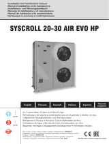
4 Unit structure
4.1 Basic unit Fan Coil
1 Air inlet (return)
2 Replaceable air filter(s)
3 Ultra efficient EC fan(s)
4 Electro- and controls cabinet
5 Mini-pipe TripleAqua heat exchanger
6 Warm water inlet
7 Return water outlet
8 Cold water inlet
9 Cold valve and actuator
10 Warm valve and actuator
11 Filter box latch for filter removal
12 Air outlet (discharge)
13 3PL.. Plenum box (separate supply)
14 Condensate drain pan
4
10
13
12
5
1
2
3
9
8
7
6
11
14
10

4 Unit structure
4.2 Drain pan
The condensate drip tray and the external connection are made of full stainless steel AISI 304
with outer insulation against condensation. In case of cleaning service, the drip tray is easy to
remove.
Due to a POSITIVE discharge pressure in the drain tray section, condensate water is additionally
driven away into the drain pipe. This positive pressure reassures that condensate water cannot
be staggered or sucked inside the drain tray. Also, the positive Pressure in the drain tray makes
it almost impossible that odours of the drain system can enter the TripleAqua unit. This design
is more costly, but avoiding contamination, cleaning, complicated service and hygienic issues
in the life time of the system matter too. Equipped as standard with close cellular expanded
synthetic insulation. The connection from the condensate tray to the external pipework is by a
strong ½”BSP thread. This solid connection avoids any leaks.
11

4.3 Ultra efficient EU5 / M5 air filter
Clean air means healthy air! The most important merit of indoor air quality is the
cleanliness. Air contamination consist of small particles that may reduce the well-
being and health of humans. Unlike other dx-units and fan coils, this is why the
TripleAqua is equipped with special (M5 to EN779) ultra-efficient micro-filtration
cassettes filters, able to filter out these particles, polls and fine dust even as small as
5μ. (0.005mm) throughout the filter’s lifetime ensuring you clean air! Close pleats
ensure lowest energy consumption, an excessive large filter area and high efficien-
cy and life span.
IMPORTANT
• Only the original filters will fit and
may be used.
• Filters cannot be cleaned.
• Filter material is enclosed by a stong,
water-resistant ABS casing.
• It is made of recyclable synthetic material.
• Filters must be replaced by original
TripleAqua spare parts.
Other types are not allowed.
• Used filters shall be disposed according
to local regulations, not in unsorted
municipal waste.
Filter replacement interval : The average usable time is 6 to 12 months. However, if
the white colour of the filter turns dark, please replace.
The filter use is always counted and checked by the controller, both in terms of
running hours as well as air volume filtered. When the FI:LT sign is shown shortly,
it is a pre-warning as it is about time to schedule a filter change soon. Meanwhile,
the unit may operate normally. Due to the extended 60mm thickness, long life and
convenient service intervals are possible. The filters can be replaced without any
tools. Clips on both side of the unit casing provide easy replacement, even in tight
surroundings. Filters come in four standard TripleAqua sizes, suitable to service all
models, limiting the number of service components. If the filter warning is ignored,
FI:LT is to be shown permanent and the unit capacity is reduced significantly, also
internal contamination will occur.
4 Unit structure
Clean air lter
Used air lter
12

4 Unit structure
4.4 EC-fan
The Motor-Ventilator is a double suction, dynamically
balanced radial forward curved with direct driven controls.
Only available with the most efficient EC Motors, mainte-
nance free bearings for long life. Unlike other fans using
plastics, our motor, the casing and the fan wheel is fully
made of strong metal parts. EC-Ventilators can operate step-
less with intelligent electronics at the lowest possible speed.
It makes them up to 75% more economic than AC fans. Ultra
low speeds are the best choice in silent applications such
as hotels. Unit may operate even lower than the human ear
threshold value!
A remarkable feature is the intelligent Motor management.
Within the operational range and external pressure, the air
volume of the fan is kept constant, regardless the change
of external pressure or operating condition. The fan just
maintains the air volume as demanded by the 0-10 V signal!
This is an important move towards full thermal control of the
unit output.
An internal thermal overload protection is as standard. These
fans set the new standard in modern fan coil applications!
As a standard, these radial ultra-low noise and low speed EC
fan(s) with extra-large wheel diameter (146mm) and forward
bended shaped blades in full metal. The fans are double
balanced and coupled directly to a very energy efficient
DC single phase electric rotor motor with internal thermal
protection incorporated in version IP 44.
Fans are housed in a metal scroll casing, aerodynamically
shaped to increase aerodynamic efficiency and minimize
noise levels. The fans are produced in best European
factories. The efficiency is by far exceeding criteria as set in
the ErP2015 directive: Even at full power, the fan(s) used in
the TripleAqua consume less than 0,095kW!
Not sensitive to external pressure
Unlike other radial fans, the TripleAqua fans have full internal
compensation for change of external pressure, reassuring
the air volume delivered at the desired level as given by
the 0-10V controls. This feature enables the system to keep
the heat transfer performance independent of external
variations, such as filter contamination, external pressure
and unforeseen conditions. Having total control over
the air volume delivered is an essential to guarantee the
performance of the indoor unit in terms of capacity and
return temperature.
4.5 Room controller
Mostly, in a room, Room Controller(s) (RC) shall be mounted.
The wired RC model is known as 3RC866.
In large (open plan) rooms, more RC of this type may be
present. It facilitates the controls and the room temperature
is measured at more locations. Maximum 6 RC can be
connected to the local bus. Each RC has a local temperature
sensor. TripleAqua calculates the average temperature of all
sensors, which will become the average room temperature.
Consumption: 7mA Max. 0.31 VA
Internal sensor: 5 .. 40 °C
Quick Time constant: 15 s
Protection class: IP30 (to EN60529)
Weight: 108 g
Color: RAL 9003 Signal White
Dimensions: 120.0 mm x 85.9 mm
13


B
FRONT VIEW
595
217
181
CONDENSATE 1/2" BSP O.D
233
C
A
FIXING POINTSM8
UNIT 3FS
ELECTRICAL BOX
TOP VIEW
INDOOR UNIT
3FS11 3FS15 3FS20 3FS25 3FS32 3FS40 3FS50 3FS60
A
530 680 830 1130 1280 1430 1580 1580
B
634 783 933 1233 1383 1533 1683 1683
C
505 655 805 1105 1255 1405 1555 1555
217
591
1
2
3
5
AIR INLET
AIR OUTLET
7
8
LEFT VERSION IS SHOWN
AIR INLET
AIR OUTLET
BACK VIEW
TOP VIEW
FRONT VIEW
TOP VIEW
WARM INLET 15mm Cu
1.
RETURN 15mm Cu
2.
COLD INLET 15mm Cu - INSULATED
3.
AIR INLET
4.
FILTER SECTION
5.
AIR OUTLET
6.
ELECTRICAL BOX
7.
CONDENSATE 1/2``BSP O.D. thread
8.
64
BACK VIEW
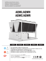
5 Unit details
5.1 Dimensional drawings
217
591
1
2
3
5
AIR INLET
AIR OUTLET
7
8
LEFT VERSION IS SHOWN
AIR INLET
AIR OUTLET
BACK VIEW
TOP VIEW
FRONT VIEW
TOP VIEW
WARM INLET 15mm Cu
1.
RETURN 15mm Cu
2.
COLD INLET 15mm Cu - INSULATED
3.
AIR INLET
4.
FILTER SECTION
5.
AIR OUTLET
6.
ELECTRICAL BOX
7.
CONDENSATE 1/2``BSP O.D. thread
8.
64
217
591
1
2
3
5
AIR INLET
AIR OUTLET
7
8
LEFT VERSION IS SHOWN
AIR INLET
AIR OUTLET
BACK VIEW
TOP VIEW
FRONT VIEW
TOP VIEW
WARM INLET 15mm Cu
1.
RETURN 15mm Cu
2.
COLD INLET 15mm Cu - INSULATED
3.
AIR INLET
4.
FILTER SECTION
5.
AIR OUTLET
6.
ELECTRICAL BOX
7.
CONDENSATE 1/2``BSP O.D. thread
8.
64
16


5 Unit details
5.2 Space requirements
For proper operation and maintenance access, a free area
around the unit has to be observed. Do not place any objects
in this area. The area is intended for free air inlet and access
to all internal parts of the unit. In the unlikely event of a se-
rious defect, large components such as air heat exchangers,
compressors or similar, need space to be able to replace.
220 mm 220 mm
250 mm
Unit
250 mm
18

5 Unit details
5.3 Technical specifications
TECHNICAL DATA INDOOR UNITS SERIES 3FS
Silent series
MODEL 3FS 11 3FS 15 3FS 20 3FS 25 3FS 32 3FS 40 3FS 50 3FS 60
Capacity heating & cooling 1,1 1,5 2,0 2,5 3,2 4,0 5,0 5,8 kW
AIR
Lowest speed ECO 90 120 160 100 125 115 135 160 m3/h
Low speed LOW 90 120 160 200 250 340 400 480 m3/h
Nominal & high speed HIGH 220 310 400 500 630 830 1000 1180 m3/h
Boost peak BOOST 270 370 460 600 760 960 1200 1330 m3/h
SIZE
Length mm
Height mm
Width 634 783 933 1233 1383 1533 1683 1683 mm
Fixing width 505 655 805 1105 1255 1405 1555 1555 mm
FILTER
Class EN 779
Depth x Height mm
Filter width 475 625 775 1075 1225 1375 1525 1525 mm
FAN
Scrolls / motors #
Type
Nom external pressure Pa
Max external pressure Pa
Motor rating kW
WATER
dT 88888999 K
Valves preset 83 115 81 95 80 90 105 120 %
Valves type Danfoss
Waterflow max. 0,035 0,048 0,062 0,073 0,100 0,113 0,132 0,150 l/s
COIL
Tube diameter mm
Water dP max 12 9 15 12 13 17 10 12 kPa
Air dP nom 15 15 16 13 15 19 32 33 Pa
Coil rows #
Max pressure bar
External connections Cu
Condensate O.D. AISI 304
SOUND
LOW 28,1 29,7 32,5 27,2 31,1 31,4 33,9 36,5 dB(A)
HIGH 43,1 45,7 46,5 46,2 49,9 47,5 49,8 51,3 dB(A)
ECO 14 19 16 11 14 15 18 20 dB(A)
LOW 14 19 16 13 16 19 22 25 dB(A)
HIGH 29 32 33 33 35 35 37 38 dB(A)
ELECTRICAL
Eco mode 56545567W
Min speed 5 6 5 8 9 15 17 22 W
Nom @ 50 Pa 28 33 38 46 56 82 110 146 W
Max @ 100 Pa 46 58 66 81 89 138 190 235 W
Supply V
WEIGHT 23 27 31 37 42 48 54 54 kg
OPTIONS
SUPPLY / RETURN PLENUM(S)
3PL11 3PL15 3PL20 3PL25 3PL32 3PL40 3PL50 3PL50
Spigots 12234455 #
Diameter mm
Air/spigot/grille 220 155 200 167 158 208 200 236 m3/h
issued : jan 2016
198
100
1/2" BSP O.D.
10
3/8"
7
DN10LF DN15LF
230 - 1f - 50Hz
Lp pressure ducted @ 1m
radiated ducted
3 x 15mm O.D.
50
DN15
4
595
217
Lw power ducted casing
free radiated
0,095
M5 / EU5
60 x 178
EC brushless inverter centrifugal direct driven - auto adjustment to any ext. pressure
1
2
3
19

/