Page is loading ...


1
in.xm
TM
spa pack error codes
- SP error codes .............................................................. 20
- SP corrective actions ....................................................22
heater error codes
- RH error codes ..............................................................26
- RH corrective actions ...................................................28
accessories error codes
- high voltage devices/accessories ...............................32
- accessories corrective actions .....................................34
testing the ozonator .....................................................................38
gfci trips .........................................................................................39
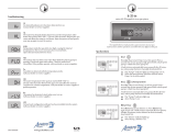
in.k600™ keypad function description ................................... 40
viewing current management data
- tech menu ......................................................................41
in.therm™
overview .......................................................................................47
installation ....................................................................................48
connecting in.therm™ to in.xm™ ...............................................49
specifications ...............................................................................50
table of contents
Table of contents
introduction ...................................................................................3
warnings .........................................................................................4
features ...........................................................................................5
overview
- in.xm™ overview .............................................................7
- in.xm™ dimensions ........................................................8
installation
- floor installation ...............................................................9
- wall installation .............................................................. 10
connections
- electrical wiring .............................................................. 11
- in.link™ connectors .......................................................13
powering up the unit ...................................................................14
in.xm™ configuration
- setting the learning mode .............................................15
- setting breaker settings ...................................................15
troubleshooting section
interface ....................................................................................... 18

2
in.xm
TM

3
in.xm
TM
introduction
in.xm
™
Most rugged spa pack platform ever
developed for spa and hot tub manufacturers.
Our new and innovative in.xm™ spa pack platform includes all
the features and functions you need in a stunning new power box
design that sets new standards with its superb combination of looks
and functionality.
With its waterproof enclosure & breakthrough connectors, in.xm™
boasts the highest water resistance ever designed in a pack, just
one of a long list of innovative features that make in.xm™ the safest
and most reliable spa pack platform ever offered to the industry.
Versatile and heater-”less”, in.xm™ can be wall-mounted or ins-
talled on its mounting base and comes with a perfect companion,
our new in.therm™ intelligent remote water heating system.
Form truly follows function in this system packed with
innovative built-in features and ground-breaking flexibility.

4
in.xm
TM
WARNINGS:
Before installing or connecting the unit,
please read the following.
* FOR UNITS FOR USE IN OTHER THAN SINGLE-FAMILY
DWELLINGS, A CLEARLY LABELED EMERGENCY SWITCH SHALL
BE PROVIDED AS PART OF THE INSTALLATION. THE SWITCH
SHALL BE READILY ACCESSIBLE TO THE OCCUPANTS AND
SHALL BE INSTALLED AT LEAST 5 FEET (1.52 M) AWAY, ADJACENT
TO, AND WITHIN SIGHT OF THE UNIT.
* ANY DAMAGED CABLE MUST BE IMMEDIATELY REPLACED.
* TURN POWER OFF BEFORE SERVICING OR MODIFYING ANY
CABLE CONNECTIONS IN THIS UNIT.
* TO PREVENT ELECTRIC SHOCK HAZARD AND/OR WATER
DAMAGE TO THIS CONTROL, ALL UNUSED RECEPTACLES
MUST HAVE A DUMMY PLUG.
* THIS CONTROLLER MUST NOT BE INSTALLED IN PROXIMITY OF
HIGHLY FLAMMABLE MATERIALS.
warnings

5
in.xm
TM
In.xm™ boast a long list of technical features. Each of them stands on its own merits and contributes to bring to spa and hot tub
manufacturers the most advanced solutions available to them:
features
In.put™ was designed to ease wire insertion (up to # 4
AWG) and connections. Tighter input connection reduces
heat generated for increased component lifetime.
In.put™
new input terminal bloc
In.seal™ provides extra level of protection against water
infiltration. Connectors and power box are designed to
be watertight and no water can be in direct contact with
electrical components.
In.seal™
watertight protection
Electronic components are placed into separate and
inaccessible compartments. Only serviceable parts are
made accessible to service technicians.
In.axess™
board access prevention
First ever UL approved kinetic heating protection manages
water temp. increase generated by pump heat dissipation.
Hardware protection shuts all accessories off if it senses
water overheat.
In.kin™
kinetic heat monitoring
A new heater safety system located in the in.therm™ power
box - an all-electronic dry-fire protection.
In.flo™
dry-fire protect
In.t.cip™ is an intelligent water temp. refresh algorithm that
calculates optimal time to start pumps and get water temp.
readings. In.t.cip™ continuously readjusts heater start time.
In.t.cip™
water temp. algorithm

6
in.xm
TM
features
Auto-diagnostic module with multiple detection levels,
in.scan™ continuously reads current at in.put™ to monitor
breaker status. It also identifi es corrective actions by
displaying error codes on the box display.
In.scan™
system auto-diagnostic
In.link™ cables are very cool output and input plugs and
connectors that come with colored and tagged polarizers.
Totally waterproof, they are designed to be easily
confi gured and to ensure that all cables of equipment
used to make a spa or an hot tub work properly are well
connected at their intended connection port, eliminating
any risk of mis-wiring.
In.link™
ingenious plugs and connectors
In.link™ output connectors:
Color Output Typical Device
Red Rh Remote Heater
Orange P1 Pump 1
Purple P2 Pump 2
Green P3 Pump 3
Red A1 General Purpose
Blue BL Blower
Green CP Circulation Pump
Gray O3 Ozone
Orange Di Audio/Video device
North
American
model
CE model

7
in.xm
TM
Fuses
Power box display and buttons
Main power
entry connection
Main power
cable input entry
Mounting feet
Installation brackets
Output connectors for
in.therm™ remote heating system
(240 vac)
2 output connectors for pumps
(rated for dual speed pumps up
to 20 amp at 240 vac only)
Pump output connector
(for 15 amp single speed pump)
(120/240 vac)
Door to access
power input
connectors and
fuses
Light or CoolRays connector
General I/O connector
(EXM-5™ or IR receiver*)
in.keys™ main and
aux. keypad connectors
Accessory connector
(in.pocket™, in.terface™,
SpaWatch™, etc.)
Connector for direct
120/240 vac 5 Amp output
(for in.play™ audio or video
accessories)
4 connectors for outputs
controlled by 4 independent
relays (for oz, cp, light, fi ber
box, blower and any other
accessories) (120/240 vac
5 Amp)
* IR receiver available on every LV connection except LI and RH
In.xm™ overview
overview
Attention: output connector confi guration
is not the same in European models.

8
in.xm
TM
In.xm™ dimensions:
3,9"
(101 mm)
2.1"
(54 mm)
16.6"
(422 mm)
9.9"
(253 mm)
6.0"
(159 mm)
17.8"
(451 mm)
.79"
(21 mm)
Ø.25"
(6 mm)
Front View Side View
overview
11"
(279 mm)
4.110"
(104 mm)
.744"
(19 mm)
Ø.25"
(6 mm)
4x
2.948"
(75 mm)
Bottom View

9
in.xm
TM
The following material is
recommended:
4- # 10 screws of appropriate
length with round, truss or pan
head.
4- washers 1/2 OD x 1/16"
thickness.
Select the most appropriate
location on the fl oor for spa
pack and fi rmly attach guide
plate to wooden base with (2)
screws backed by (2) washers.
Slide back side of the unit's foot
into the guide plate. It should
easily slide into place.
Now fi rmly attach unit to
wooden base by using the
remaining (2) screws backed
by (2) washers to fi x the front of
the foot.
Note: The spa pack must be
installed at least 4 inches above
potential fl ood level. If fl oor is
on ground level, pack should
be raised at least 4 inches.
Floor installation procedure
4"
Warning:
Beware the application of some products commonly used against
corrosion (such as WD-40 family products) could damage the
power box, due to a negative chemical reaction between some
industrial oils and its plastic enclosure. Any other materials
which may come in contact with the enclosure must be carefully
evaluated under end use conditions for compatibility.
Important!
Please note that countersunk
screws should not be used as
they can damage the power
box support.
installation

10
in.xm
TM
Firmly attach lower mounting
holes on each side of the pack
with the (2) remaining screws
and (2) washers.
Note: Make sure these (2)
screws and (2) washers are
installed. They will make
the pack stable when input,
outputs and acessories
connectors will be manually
inserted in their ports.
The following material is recommended:
4- # 10 screws of appropriate length with round, truss or pan head.
4- washers 1/2 OD x 1/16" thickness.
Select the most appropriate location on wall for spa pack and
fi rmly attach, one at the time, upper mounting holes on each side
of the spa pack to wall with (2) screws backed by (2) washers.
Wall installation procedure
installation

11
in.xm
TM
Warning!
"For units for use in other than single-family dwellings, a clearly
labeled emergency switch shall be provided as part of the installa-
tion. The switch shall be readily accessible to the occupants and
shall be installed at least 5 feet (1.52 m) away, adjacent to, and
within sight of the unit".
Main electrical box GFCI panel
For 240 VAC (*3 wires)
*If connected to a 3 wire system
(without neutral), all 120 VAC
components will not work.
For 240 VAC (4 wires)
Correct wiring of the electrical
service box, GFCI, and pack
terminal block is essential.
Call an electrician if necessary.
Electrical wiring
connections

12
in.xm
TM
Warning!
This product must always
be connected to a circuit
protected by a ground fault
interrupter.
Proper wiring of the electrical
service box, GFCI and in.xm™
terminal block is essential!
Check your electrical code for
local regulations. Only copper
wire should be used, never
aluminum.
Connect the bonding conduc-
tor to the bonding lug on the
left side of the in.xm™ spa pack
(a grounded electrode conduc-
tor shall be used to connect
the equipment grounding con-
ductors).
*Note : It's recommended to
use a waterproof strain relief,
rated IPX5 or greater.
Bonding lug
To install the wiring for the
in.xm™ spa control, you'll need
a Phillips screwdriver, a
9/16"
nut driver or a fl at screwdriver.
Loosen the 2 screws of the spa
pack door and open it. Remove
8" of cable insulation. Strip
away 1" of each wire insulation.
Pull the cable through the cut-
out of the box and secure it
with a strain relief (1" NPT trade
size)*. Make sure that only the
uncut sheathing is clamped at
this opening. Push the color-
coded wires into the terminals
as indicated on the sticker and
use the
9/16" wrench or fl at
screwdriver to tighten the bolts
on the terminals.
After making sure wire connec-
tions are secure, push them
back into the box and close the
door. Tighten the 2 screws of
the spa pack door.
Electrical wiring
connections

13
in.xm
TM
in.link™ connectors
In.xm™ features in.link™ connectors with colored and tagged
polarizers. This new plug and connector technology has been
specifi cally designed for easy and safe assembly. The tags are
interchangeable depending on the output; the polarizers are
designed to avoid misconnections.
In.link™ connectors are easily and conveniently accessible from
the front of the pack offering a wide range of possible connection
confi gurations. In.link™ connectors come in 3 sizes (HC, LC and
low voltage) for all types of inputs and output devices.
Heater
communication cable
Heater
power cable
They all include an integrated
latch that keeps them safely in
place and provides audible and
tactile feedback when properly
connected.
Finally, colored and tagged
polarizers provide a defi nite
advantage in reducing SKU
numbers and inventory
levels thus giving OEMs and
dealers total fl exibility to easily
confi gure output devices.
connections

14
in.xm
TM
Make sure all accessories
are linked to the bonding
connector and connected
to pack.
Make sure the spa pack door
is closed.
Turn on the breaker.
Press Select button to change
breaker setting.
The in.scan™ display will show
the breaker setting menu.
It is important to specify the
current rating of the GFCI used
to insure safe and effi cient
current management (and no
GFCI trippings).
Bonding lug
Br values displayed by the
system correspond to 0.8 of
the maximum amperage
capacity of the GFCI.
GFCI Br
60 Amp 48 Amp
50 Amp 40 Amp
40 Amp 32 Amp
30 Amp 24 Amp
Note: Every OEM has its own preset
confi gurations.
Use Change button to set the
current breaker rating then
press Select button.
All receptacles will match
the corresponding female
connection on the spa pack.
No connectors should remain
unplugged. Use blank plugs to
fi ll unused connectors.
powering up the unit

15
in.xm
TM
Press and hold Select button for 5 seconds to
activate low level programming. Once activated,
the display shows “LL” and, in succession, the
current preset low level configuration selected.
Press Change button repeatedly to select the
the same preset low level configuration again.
Press Select to confirm. You will exit menu
automatically. The in.xm™ will then reset. After
resetting, the system starts a "learning sequence"
in which each individual output is activated and
its peak current displayed and saved.
Setting the learning mode
The in.xm™ pack has the ability to verify and "learn" the current
consumption of every output connected to it. If an output is
replaced, a new learning must be done. Follow these simple steps:
Note: if unusual current readings e.g.: 4 to 6 amps are detected on
the high speed of any pump, all pumps must be primed and the
learning mode should be restarted.
Note: Every OEM has its own preset configurations.
Select button is used to access the breaker setting
menu (short press) as well as the low level pro-
gramming menu (Press and hold for 5 seconds).
Subsequent presses will save changes and
display the next option available or exit
automatically if it was the last one.
Use Change button to change the parameters
displayed.
Press Select button once to activate the breaker
setting menu. Once activated, the display shows
“br” and, in succession, the maximum current
rating of the breaker.
Press Change button
to change setting.
Press Select to confirm. You will exit menu
automatically (in.xm™ will also reset).
Selecting Breaker (Br) settings
Description
Note: this procedure has to be performed
after every learning mode.
in.xm
TM
configuration


18
in.xm
TM
Note: Every OEM has its own preset confi gurations.
In.xm™ troubleshooting advantage
In.xm™ unique troubleshooting features are called in.scan™
because in.xm™ has the capacity to scan itself and read the status of
all exterior connected devices.
All errors codes will be displayed on the keypad and on the in.xm™
display, making reading codes easier and more convenient.
Error codes
Error codes indicate a failure condition or a problem which needs
to be corrected to ensure proper functioning of the system. Both
the error code and device identifi cation are alternatively displayed.
interface
/