Page is loading ...


1
in.k400
Table of contents
overview ......................................................................................... 3
installation
- drilling template ..............................................................5
- with adhesive ...................................................................6
- with brackets ....................................................................6
connections
- connecting in.k400 keypad to in.xm ............................7
functions
- on/off key .........................................................................8
- pumps 1 & 2 keys .............................................................8
- pump 3 & blower key .....................................................9
- light key .............................................................................9
- up/down keys .................................................................9
- program key .....................................................................9
- setting time ..................................................................... 10
- setting fi lter cycle ........................................................... 10
- setting temperature unit ................................................ 11
- other features .................................................................. 11
specifi cations ................................................................................12
table of contents


3
in.k400
On/Off key
Pump 1 key
Program key Light key
Up/Down key
Pump 2 key
2 pump system
in.k400
Compact full-featured keypads
that gives complete control to wet fi ngers
Aeware’s new series of keypads features a large LCD display
and raised keys that let users control all in.xm functions and
programming directly from spa side. In.k400 comes in an easy to
install waterproof plastic enclosure and is designed to maximize
user experience.
On/Off key
Pump 1 key
Pump 3 key Light/Program
key
Up/Down key
Pump 2 key
3 pump system
overview

4
in.k400
Set Point icon
The "Set Point" icon
automatically turns on
when set point setting
menu is activated.
(SP message on display).
Filter Cycle icon
The "Filter Cycle" icon lights
up when fi lter cycle is on.
Pumps icon
The "Pump" indicator
numbers light up and their
icons become fast animated
when pump or blower are in
high speed, slower animated
icon when pump or blower
are in low speed.
Heater icon
The "Heater" icon lights
up when the heater is on.
It fl ashes when:
1- there is a call for heat
and heater has not
started yet,
2- heater has just turned
off and element is
cooling down or
3 - not enough current
available to start heater
Light icon
The "Light" icon lights
up when the light is on.
The icon's number of
rays is proportional to
the light's intensity.
Smart Winter Mode icon
The "SWM" icon automa-
tically turns on when freeze
protection is active. It fl ashes
while system purges the spa
plumbing.
Time, temperature
& message digits
Service icon
A problem has
been detected. Do
not enter the water!
Spa service is
required.
Progress bar
A visual indication of
the time remaining
before an equipment
is turned off or
before the end of the
standby mode.
AM/PM (˚F/ ˚C)
overview


6
in.k400
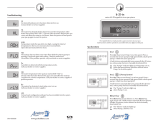
To install the in.k400, the user must cut out one 7/8" diameter hole
for the cable (see illustration).
Clean the installation surface and peel the adhesive gasket from the
back of the keypad.
Insert keypad and align it correctly, then ensure it's properly glued
by gently pressing evenly on the entire surface.
To install the in.k400, the user must cut out two 1/4" diameter
holes for the fixation studs and one 7/8" diameter hole for the
cable (see illustration).
Insert keypad and align it correctly, then secure it properly in place
by using the two wing nuts provided.
7/8"
Gasket with adhesive
Installation in.k400 with adhesive Installation in.k400 with brackets
1.60"
2 x 1/4"
7/8"
Gasket with or
without adhesive
Optional
wing nuts
1.50"
installation


8
in.k400
On/Off key
Depending on the spa manufac-
turer, this key may have differ-
ent functions: On/Off, Standby
mode or quick enable of the
Economy mode.
Standby Mode : Use On/Off
key to pause all pumps*.
Progress bar will display the
remaining time before the
system automatically exits
Standby mode (user can also
exit Standby mode at any time
by pressing again on On/Off key).
In order to warn the user, the
spa light will fl ash for a few
seconds before the exit of
Pump 1 key
Press Pump 1 key to turn
Pump 1 on at low speed.
Press a second time to turn
pump to high speed (with a
dual-speed pump).
A third time turns pump off.
A built-in timer automatically
turns pump off after 20 min-
utes, unless pump has been
manually deactivated fi rst.
Pump 2 key
Press Pump 2 key to turn
Pump 2 on at low speed.
Press a second time to turn
pump to high speed (with a
dual-speed pump).
A third time turns pump off.
A built-in timer automatically
turns pump off after 20 min-
utes, unless pump has been
manually deactivated fi rst.
Standby mode and restart the
pumps. The "Stby" message is
also displayed during Standby
mode.
* Pump will stay turned on if
there is a request for more heat.
functions

9
in.k400
Light key
Press Light key to turn light on
at high intensity.
Subsequent presses change
light intensity.
A last press turns light off.
A built-in timer automatically
turns light off after 2 hours,
unless it has been manually
deactivated fi rst.
Up/Down keys
Use Up or Down key to set
desired water temperature.
The temperature setting will
be displayed for 5 seconds to
confi rm your new selection.
The "Set Point" icon indicates
that the display shows the
desired temperature, NOT the
current water temperature!
Program key
Use Program key to display
time or enter Programming
menu by pressing and holding
key. In Programming mode, the
following parameters can be
set: time, fi lter cycle start time,
fi lter cycle duration, fi lter cycle
frequency, and temperature
unit.
Note: Light key is used as
Program key if this key is not
present.
Pump 3/Blower key
Press Pump 3/Blower key to
turn Pump 3/Blower on.
Press a second time to turn
pump off.
A built-in timer automatically
turns pump off after 20 min-
utes, unless pump has been
manually deactivated fi rst.
functions

10
in.k400
Setting the time
Enter Programming mode by
holding Prog. key pressed
down for 3 sec. The display will
show the current time setting.
Setting the hour:
Use Up or Down arrows to
change hour setting (AM/PM).
Setting the minutes:
Press Prog. key a second time.
Use Up or Down key to change
hour setting.
Setting fi lter cycle start time
To program the fi lter cycle, you
must enter these parameters:
the start time, duration and
frequency. During a fi lter
cycle, pumps run for one min-
ute to purge the plumbing,
then Pump 1 runs for the
programmed number of hours.
Press Prog. key a third time.
The display will show FSxx, with
"xx" representing the starting
hour.
Use Up or Down key to change
setting.
Setting fi lter cycle duration
Press Prog. key a fourth time.
The display will show Fdxx, with
"xx" representing the duration
in hours.
Use Up or Down key to change
setting.
Filter cycle frequency
Press Prog. key a fi fth time.
The display will show FFxx, with
"xx" representing the number of
fi lter cycles per day (up to 4).
Use Up or Down key to change
setting.
functions

11
in.k400
Water temperature
regulation
In a regulation cycle, the system
fi rst generates water fl ow
through the heater housing
and the plumbing, in order
to ensure accurate water
temperature readings as well as
avoiding heater activation in dry
conditions.
After verifying pump activation
and taking a water temperature
reading if required, the system
automatically turns the heater
on to reach and maintain water
temperature at Set Point.
Cooldown
After heating the spa water to
the desired Set Point, the heater
is turned off, but its associated
pump (Pump 1 Low-speed or
CP) remains on for a
predetermined period of time
to ensure adequate cooling
of the heating element, this
prolongs its useful life. The
heater icon fl ashes during this
time.
Smart Winter Mode
Our Smart Winter Mode
protects your system from
the cold by turning pumps on
several times a day to prevent
water from freezing in pipes.
Setting temperature unit
Water temperature can be
displayed in either Fahrenheit
(˚F) or Celsius (˚C).
Press Prog. key a sixth time.
The display will show either
˚F or ˚C.
Use Up or Down key to change
setting.
functions

12
in.k400
General specifi cations:
Environmentals:
Storage temperature: 70˚C (158˚F) to –30˚C (-22˚F)
Operating temperature: 60˚C (140˚F) to –20˚C (-4˚F)
Humidity: up to 95% condensing
Mechanical Specs:
Weight: 0.27 kg (0.6 lbs)
Dimensions (W x H x D): Front Panel:
162 mm x 56 mm x 19 mm
(6 3/8" x 2 7/32" x 3/4") Soft gasket
Standards: UL 1563 Fifth Ed. File: E182156
CSA No. 22.2 - 218.1-M89
Dimensions:
2 7/32"
(56 mm)
6 3/8"
(162 mm)
Specifi cations and design are subject to change without notice.
3/4"
(19 mm)
(19 mm)
3 3/32"
(79 mm)
1 15/32"
(37 mm)
specifi cations
13/32"
(10 mm)

/