Page is loading ...


Table of Contents
Preliminary
Required Material
3
Keypads
4
Miscellaneous
Parts List 60
Wiring Diagram 61
Professional Repair Kit 62
How to
Replace The Spa Pack 55
Adjust The Pressure Switch 58
Troubleshooting
Nothing Works! 35
Spa Is Not Heating! 37
Pump 1 Does Not Work! 41
Pump 2 (or Blower) Does Not Work! 45
Spa Light Does Not Work! 49
Ozonator Does Not Work! 51
Keys Do Not Work! 53
Programming
Jumper Positions
8
Power & Ground Check
GFCI
5
Electrical Wiring 6
GFCI Trips!
7
Error Conditions
3 Flashing Dots Appearing On Keypad Display 9
3 Flashing Dots & LED Displayed 13
Display Is Flashing 17
Wrong Temperature Appearing On Keypad Display 21
FLO 23
FLC 27
Prr 29
HL (OH) 31

Important Safety Information
WARNING: Risk of electrical shock! All procedures described in this service
manual must only be performed by qualified personnel, in
accordance with the standards applicable in the country of
installation and, whenever possible, with the equipment
powered off. When connecting the equipment, always refer to
the wiring diagram affixed to the inside of your spa pack’s
power box cover. This diagram always prevails over the wiring
diagram at the end of this manual.
All information given subject to technical modifications without notice.
In order to be as helpful as possible, most sections of this manual were written in two
distinct formats: problem-solving solutions are described using both troubleshooting
flow charts and step-by-step procedures.
They should be used in conjunction, flow charts giving a global overview of specific
problems while step-by-step procedures are more detailed.
Although this manual has been prepared with great care, some information may seem
erroneous or unclear to you. In this case, please do not hesitate to contact us with
your remarks or questions.

Pack Parts:
Pliers
Phillips & flat screwdrivers
11/32" (M8) nut driver
1/4" (M6) open-end wrench
3/8" (M10) open-end wrench
Jumper cable
Multimeter
GFCI tester & digital thermometer (optional)
Keypad
SC
-CF system board
(or complete spa pack)
Required Material
The tools, test equipment and components needed to carry out SC-CF
Spa Pack service calls.
Tools & Test Equipment:
Fuses
Temperature probe
Hi-limit sensor
Pressure switch
Notes: The equipment delivered may slightly differ from the illustrations shown in this manual.
Spa Builders Systems Group sells Professional Repair Kits that include everything needed
for SC
-CF Spa Pack servicing. For more information, go to the last page of this manual.

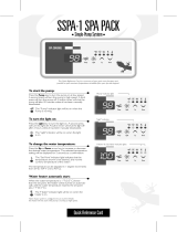
Keypads
SC-CF single-pump and dual-pump systems are available with several
types of keypads.
Described procedures and instructions apply to SC-CF systems equipped with one of the
following keypads. For convenience purposes, the K-9 model will be used throughout this
manual to illustrate specific actions to be performed.
Please note that key location can vary from one software to another. Refer to the Spa Pack
Quick Reference Card (QRC) if needed.
K-18 model (127 mm x 63 mm)
K-9 model (114 mm x 51 mm)
K-19 model (177 mm x 82 mm)
4
Service Manual SC-CF CE & AS
5
Service Manual SC-CF CE & AS

If GFCI trips, follow Troubleshooting Flow Chart below to identify
the problem:
Is GFCI
properly
connected?
If GFCI is
still tripping,
disconnect
power input
wires.
Is GFCI still
tripping?
Replace
GFCI.
Replace
Spa Pack.
The cable
is defective.
Call an
electrician!
Reconnect
one component
at a time
until GFCI
starts tripping.
Replace
defective
component.
Verify
GFCI wiring
diagram
&
reconnect it.
yes
yes no
no
yes no
Disconnect all
outputs,
including the
two heater
blades & the
light cord.
Is GFCI still
tripping?
GFCI Flow Chart
4
Service Manual SC-CF CE & AS
5
Service Manual SC-CF CE & AS

Note: For systems manufactured before 1999, if P33 & P34 are missing,
install a 4-mm dia. cable between Line 1 and Line 2.
1 x 230 VAC (32 A) input supply wiring
Correct wiring of the electrical service box, GFCI and spa pack terminal
block is essential.
• Make a visual inspection for signs of miswiring. Refer to the supplied wiring
diagram. Call an electrician if necessary.
Electrical Wiring
Jumper JMP1 set in "HC" mode!
Note: For systems manufactured before 1999, if P33 & P34 are missing,
install a 4-mm dia. cable between Line 1 and Line 2.
1 x 230 VAC (16 A) input supply wiring
Jumper JMP1 set in "LC" mode!
2 x 230 VAC (2 x 16 A) input supply wiring
NOT ALLOWED IN AUSTRALIA
INPUT
CABLE
LINE
GROUND
LINE 1
NEUTRAL
LINE 2
NEUTRAL
USE OP-
TIONAL
JUMPER
P34
P33
LINE
GROUN
D
LINE
1
NEUTRAL
LINE
2
NEUTRAL
INPUT
CABLE
USE OP-
TIONA
L
JUMPER
P34
P33
INPUT
CABLE
INPUT
CABLE
NEUTRAL
NEUTRAL
LINE
2
LINE
1
NEUTRAL
LINE
LINE
6
Service Manual SC-CF CE & AS
7
Service Manual SC-CF CE & AS

GFCI Trips!
1• Verify if GFCI is properly connected.
2• If it is not, verify GFCI wiring diagram
and reconnect it.
If the equipment is connected but nothing seems to work, the power supply
must be defective. Perform the following:
Note that in new installations, GFCI trippings due to miswiring are very common.
If breaker is properly wired, GFCI trippings can occur when the total amount of current
drawn by the spa exceeds the rating of the breaker. Such an occurrence, however, is very
unlikely since each output of the spa pack is individually fused and fuses will blow before
GFCI trips.
A current leak to the ground will also make GFCI trip. If one of the components is faulty
and there is a leak of more than 5 mA, GFCI will trip to prevent electrocution.
3• If GFCI is properly connected but still
tripping,
disconnect
all outputs,
including the
two heater
blades & the
light cord.
4• If it stops tripping, reconnect one
component at a time until GFCI
starts tripping again. Then replace
the defective component.
5• If problem is still not solved, discon-
nect the power input wires on the
board.
If GFCI still trips, the cable must be
defective.
Call an electrician!
6• If GFCI stops tripping, replace it.
7• If GFCI is still tripping, replace Spa
Pack.
6
Service Manual SC-CF CE & AS
7
Service Manual SC-CF CE & AS

Jumper Positions
2• To change a setting, simply pull cover
off and replace in desired position.
Certain parameters can be modified by changing the position of jumpers on
the board.
To access jumpers, first remove SC-CF power box cover.
In some cases, jumper functions may differ from the following. Please check wiring diagram
on power pack box cover to verify specific functions for your pack.
1• Jumpers are located in the lower right
section of the board.
Position 2Position 1
Jumper location
Jumper JMP1: Current Limiting Option
This jumper is used to limit the current drawn when the two pumps
are activated simultaneously.
Position 1 (HC): High Current mode. No current restriction.
Position 2 (LC): Low Current mode. The heater may not be turned
on if pump is on at high speed. Factory default setting.
Jumper JMP2: Temperature Display Unit
Position 1: Temperature will be displayed in degrees Fahrenheit (ºF).
Factory default setting.
Position 2: Temperature will be displayed in degrees Celsius (ºC).
Jumper JMP3: Pump
Position 1: Single-pump system. Factory default setting.
Position 2: Dual-pump (or pump & blower) system.
8
Service Manual SC-CF CE & AS
9
Service Manual SC-CF CE & AS

Flashing Dots Flow Chart
If 3 flashing dots appear on keypad display, follow Troubleshooting Flow
Chart below to identify the problem:
3 flashing dots appear on the display!
Remove pack cover.
Is board LED on?
Follow
flashing dots
& LED flow chart.
yes no
Make sure jumper is
set properly for
circulation pump
(if present) and
reset breaker
.
Start Pump 1 (or
circulation pump if installed
by increasing set point).
Replace pressure
switch if problem
persists.
Do you have
continuity on your
voltmeter for
pressure switch?
yes
no
Short pressure
switch terminals
with a jumper cable.
Replace pressure
switch cable
(if replaceable).
Replace pressure
switch cable
(if replaceable).
Remove anything
obstructing filter canister
or piping. Clear any air
locks. Verify water valves.
Try to adjust
pressure switch.
Are dots still
flashing on
keypad display?
If problem persists,
replace Spa Pack.
yes
no
Verify
pressure
switch
connection.
Try to adjust
pressure switch.
Disconnect
pressure switch
for 5 seconds
and reconnect it.
Are dots still
flashing on
keypad display?
If problem persists,
replace Spa Pack.
yes
no
Replace pressure
switch if problem
persists.
8
Service Manual SC-CF CE & AS
9
Service Manual SC-CF CE & AS

Flashing Dots Displayed
Three flashing dots error condition indicates a pressure switch problem.
There must be enough water in the spa for normal operations. System may detect error
condition if spa filter is dirty or if something restricts flow of water in piping.
The heater will automatically shut down when error condition occurs.
Power may remain On when the following steps are carried out.
5• If you do not detect continuity,
verify if pressure switch cable is
properly connected to pressure
switch and board.
1• Make sure jumper is set pro
-
perly for circulation pump (if
present). See jumper settings
for more details (p.8).
2• Verify if Pump 1 (or circulation
pump if installed) is working. If
pump is not working right, refer
to pump section of this manual.
3• If Pump 1 is working properly
,
turn it on by pressing Pump
1
key (or start circulation pump
by increasing the set point) and
test continuity on pressure switch.
4• If you detect continuity, go to
step #10.
10
Service Manual SC-CF CE & AS
11
Service Manual SC-CF CE & AS

Flashing Dots Displayed
6• Ensure adequate water flow in
the heater and short two pres-
sure switch terminals with jumper
cable.
7• If the three dots disappear, first
make sure there is no blockage
of water or air lock and check
water valves.
If the installation is older than
2
years, replace pressure switch
and recalibrate it.
If installation is recent, try read-
justing the pressure switch. If this
is not possible, replace switch.
(Refer to "How to Adjust the
Pressure Switch" section of this
manual.)
8• If the three dots still appear
,
the problem may be either with
switch cable or board.
Remove plastic cover and re-
place cable (if replaceable).
9•
Replace Spa Pack if error con-
dition still persists. (Refer to "How
to Replace the Spa Pack" section
of this manual.)
10
Service Manual SC-CF CE & AS
11
Service Manual SC-CF CE & AS

Flashing Dots Displayed
Power may remain On while the following steps are carried out.
11• If error condition persists, remove
plastic cover and replace pressure
switch cable (if replaceable).
12• Replace Spa Pack if error condition
still persists. (Refer to "How to Re-
place the Spa Pack" section of this
manual.)
10• If you have continuity on pressure
switch, follow these steps:
Disconnect pressure switch cable
for 5 seconds and reconnect it.
If error condition disappears, ad-
just pressure switch, if it is a new
installation (less than two years) or
replace it.
(Refer to "How to Adjust the
Pressure Switch" section of this
manual.)
12
Service Manual SC-CF CE & AS
13
Service Manual SC-CF CE & AS

Flashing dots & LED Flow Chart
Take water temperature
with a digital thermometer
.
Are you getting correct
water temp. reading on the display?
yes no
Replace Spa Pack
if error condition
still persists.
Verify if
temperature probe
is properly connected.
If so, replace probe
and reset breaker
.
Verify if
temperature probe
is touching water
or if cold air from
back can affect
reading.
Is HL probe
properly connected
(verify probe only
if replaceable)?
Clean pins,
reconnect
it, and reset
the breaker
.
Verify if anything
is obstructing water
flow (closed traps or
dirty filters).
If error condition
persists, replace probe
(if replaceable)
and reset breaker
.
When error
condition occurs,
does heater
barrel feel hot?
yes
no
If error condition still
persists, replace Spa Pack.
Turn breaker off then on again to reset the system.
If Hi-Limit condition no longer persists, check for blockage
of water in the piping.
If error condition occurs (potential Hi-Limit sensor or temperature probe
problem), follow Troubleshooting Flow Chart below to identify the problem:
12
Service Manual SC-CF CE & AS
13
Service Manual SC-CF CE & AS

Flashing Dots & LED Displayed
Turn breaker off then on again to reset the system.
If 3 flashing dots and LED disappear, wait until they are displayed again on keypad.
Power may remain On.
c- If error condition persists, re-
place probe (if replaceable only)
and reset breaker
.
d- If problem is not solved, replace
Spa Pack. (Refer to "How to Re
-
place the Spa Pack" section of this
manual.)
3•
Proceed to following page if key-
pad display shows incorrect tem-
perature.
1•
Take water temperature with a
digital thermometer.
2• If keypad display shows correct
temperature:
a- Check if heater barrel feels hot.
If it's hot, verify if anything is
obstructing the flow of water
(closed valves or dirty filter).
b- If it's not, verify if hi-limit probe
is properly connected (check
probe only if replaceable).
Try to clean probe connector
pins. Even a small coating of film
may cause a bad connection.
Reconnect probe and reset
breaker.
The three flashing dots and LED error condition is related to the Hi-Limit
sensor or temperature probe.
14
Service Manual SC-CF CE & AS
15
Service Manual SC-CF CE & AS

Flashing Dots & LED Displayed
If keypad display isn't showing correct temperature, carry out the
following tests:
2• Make sure temperature probe
is properly connected.
If it is, replace probe and reset
breaker
.
3•
Replace Spa Pack if error con-
dition still persists. (Refer to
"How to Replace the Spa Pack"
section of this manual.)
1•
Verify if temperature probe
is in contact with water and if
cold air from the back could
be affecting readings.
Use foam to isolate probe from
cold air if that is the problem.
14
Service Manual SC-CF CE & AS
15
Service Manual SC-CF CE & AS

16
Service Manual SC-CF CE & AS
17
Service Manual SC-CF CE & AS

Display Flashing Flow Chart
On certain packs, if system detects temperature at 44°C (112°F) or
higher, the display will start flashing. Follow Troubleshooting Flow Chart
below to identify the problem:
Are you getting correct
water temp. reading on the display?
Replace
Spa Pack if
problem
still persists.
Verify if
temperature probe
is properly connected.
If so, replace probe
and reset breaker
.
Verify if
temperature probe
is touching water
or if cold air from
back can affect
reading.
Remove
spa cover
(even during
the night).
Start
blower, if
spa is
equipped
with one.
Wait until
spa cools
down (add
cold water
if needed).
Pump is
overheating
water during
filter cycle.
Lower
filter cycle
duration.
Replace
Spa Pack.
Lower set point
below actual
temperature of
water
.
"Heater" indicator
on keypad display
should disappear
.
Do you get
a
240 VAC reading
between
two heater wires
on the board?
yes no
Is weather
very hot?
yes no
yes no
A power failure
has occurred.
System
works fine.
Press
any key
.
Has display
stopped flashing?
yes no
16
Service Manual SC-CF CE & AS
17
Service Manual SC-CF CE & AS

Display Is Flashing
If digital thermometer water temperature reading is 44°C (112°F) or
higher and keypad display indicates correct temperature, carry out the
following tests:
If display stops flashing after pressing a key, this means that a power failure has occurred.
System works fine.
If weather is very hot:
1• Remove spa cover (even during
the night). Start blower if spa is
equipped with one. Wait until
spa cools down (add cold water
if necessary).
If hot weather is not a factor:
2•
Lower set point below current
water temperature.
"Heater" indicator should disappear
from keypad display.
4• If you do not read 240 VAC, pump
may be overheating water during
filter cycle.
Enter Programming mode and
shorten filter cycle duration.
5• If you do read 240 VAC, test the
element. If it is opened, replace
it. If element works fine, replace
Spa Pack.
(Refer to "How to Replace the
Spa Pack" section of this manual.)
3• Remove spa cover. With a volt-
meter, read the voltage between
the two heater wires on the board.
18
Service Manual SC-CF CE & AS
19
Service Manual SC-CF CE & AS

Display Is Flashing
If digital thermometer water temperature reading is 44°C (112°F) or
higher and keypad display isn't showing correct temperature, carry out
the following tests:
2• Make sure temperature probe
is properly connected.
If it is, replace probe.
3•
Replace Spa Pack if display is still
flashing.
(Refer to "How to Replace the
Spa Pack" section of this manual.)
1•
Verify if temperature probe
is in contact with water and if
cold air from the back could
be affecting readings.
Use foam to isolate probe from
cold air if that is the problem.
18
Service Manual SC-CF CE & AS
19
Service Manual SC-CF CE & AS
/