Page is loading ...

20043127 (3) - 10/2012
Installation, use and maintenance instructions
Dual fuel light oil/gas burner
Progressive two stage or modulating operation
CODE MODEL
20042895 RLS 70/E
GB


1 20043127
GB
Contents
1 Information and general instructions . . . . . . . . . . . . . . . . . . . . . . . . . . . . . . . . . . . . . . . . . . . . . . . . . . . . . . . . . . . . . . . . . . . . . 3
1.1 Information about the instruction manual . . . . . . . . . . . . . . . . . . . . . . . . . . . . . . . . . . . . . . . . . . . . . . . . . . . . . . . . . . . . 3
1.1.1 Introduction . . . . . . . . . . . . . . . . . . . . . . . . . . . . . . . . . . . . . . . . . . . . . . . . . . . . . . . . . . . . . . . . . . . . . . . . . . . . . . . . . . 3
1.1.2 General dangers . . . . . . . . . . . . . . . . . . . . . . . . . . . . . . . . . . . . . . . . . . . . . . . . . . . . . . . . . . . . . . . . . . . . . . . . . . . . . . 3
1.1.3 Safety precautions . . . . . . . . . . . . . . . . . . . . . . . . . . . . . . . . . . . . . . . . . . . . . . . . . . . . . . . . . . . . . . . . . . . . . . . . . . . . . 3
1.1.4 Danger: live components . . . . . . . . . . . . . . . . . . . . . . . . . . . . . . . . . . . . . . . . . . . . . . . . . . . . . . . . . . . . . . . . . . . . . . . . 3
1.2 Guarantee and responsibility . . . . . . . . . . . . . . . . . . . . . . . . . . . . . . . . . . . . . . . . . . . . . . . . . . . . . . . . . . . . . . . . . . . . . 4
1.2.1 Owner’s responsibility . . . . . . . . . . . . . . . . . . . . . . . . . . . . . . . . . . . . . . . . . . . . . . . . . . . . . . . . . . . . . . . . . . . . . . . . . . 4
2 Safety and prevention. . . . . . . . . . . . . . . . . . . . . . . . . . . . . . . . . . . . . . . . . . . . . . . . . . . . . . . . . . . . . . . . . . . . . . . . . . . . . . . . . . 5
2.1 Introduction . . . . . . . . . . . . . . . . . . . . . . . . . . . . . . . . . . . . . . . . . . . . . . . . . . . . . . . . . . . . . . . . . . . . . . . . . . . . . . . . . . 5
2.2 Personnel training . . . . . . . . . . . . . . . . . . . . . . . . . . . . . . . . . . . . . . . . . . . . . . . . . . . . . . . . . . . . . . . . . . . . . . . . . . . . . 5
3 Technical description of the burner . . . . . . . . . . . . . . . . . . . . . . . . . . . . . . . . . . . . . . . . . . . . . . . . . . . . . . . . . . . . . . . . . . . . . . 6
3.1 Technical data . . . . . . . . . . . . . . . . . . . . . . . . . . . . . . . . . . . . . . . . . . . . . . . . . . . . . . . . . . . . . . . . . . . . . . . . . . . . . . . . 6
3.2 Electrical data. . . . . . . . . . . . . . . . . . . . . . . . . . . . . . . . . . . . . . . . . . . . . . . . . . . . . . . . . . . . . . . . . . . . . . . . . . . . . . . . . 6
3.3 Burner models designation . . . . . . . . . . . . . . . . . . . . . . . . . . . . . . . . . . . . . . . . . . . . . . . . . . . . . . . . . . . . . . . . . . . . . . 7
3.4 Burner description . . . . . . . . . . . . . . . . . . . . . . . . . . . . . . . . . . . . . . . . . . . . . . . . . . . . . . . . . . . . . . . . . . . . . . . . . . . . . 8
3.5 Packaging - weight - Approximate measurements. . . . . . . . . . . . . . . . . . . . . . . . . . . . . . . . . . . . . . . . . . . . . . . . . . . . . 9
3.6 Burner dimensions . . . . . . . . . . . . . . . . . . . . . . . . . . . . . . . . . . . . . . . . . . . . . . . . . . . . . . . . . . . . . . . . . . . . . . . . . . . . . 9
3.7 Standard equipment. . . . . . . . . . . . . . . . . . . . . . . . . . . . . . . . . . . . . . . . . . . . . . . . . . . . . . . . . . . . . . . . . . . . . . . . . . . . 9
3.8 Firing rate. . . . . . . . . . . . . . . . . . . . . . . . . . . . . . . . . . . . . . . . . . . . . . . . . . . . . . . . . . . . . . . . . . . . . . . . . . . . . . . . . . . 10
3.8.1 Procedure to refer burner operating condition in high altitude plants. . . . . . . . . . . . . . . . . . . . . . . . . . . . . . . . . . . . . . 10
3.9 Minimum furnace dimensions . . . . . . . . . . . . . . . . . . . . . . . . . . . . . . . . . . . . . . . . . . . . . . . . . . . . . . . . . . . . . . . . . . . 12
3.10 Control box for the air/fuel ratio (LMV36...) . . . . . . . . . . . . . . . . . . . . . . . . . . . . . . . . . . . . . . . . . . . . . . . . . . . . . . . . . 13
3.11 Actuators (SQM33.5...) . . . . . . . . . . . . . . . . . . . . . . . . . . . . . . . . . . . . . . . . . . . . . . . . . . . . . . . . . . . . . . . . . . . . . . . . 16
4 Installation. . . . . . . . . . . . . . . . . . . . . . . . . . . . . . . . . . . . . . . . . . . . . . . . . . . . . . . . . . . . . . . . . . . . . . . . . . . . . . . . . . . . . . . . . . 17
4.1 Notes on safety for the installation. . . . . . . . . . . . . . . . . . . . . . . . . . . . . . . . . . . . . . . . . . . . . . . . . . . . . . . . . . . . . . . . 17
4.2 Handling. . . . . . . . . . . . . . . . . . . . . . . . . . . . . . . . . . . . . . . . . . . . . . . . . . . . . . . . . . . . . . . . . . . . . . . . . . . . . . . . . . . . 17
4.3 Preliminary checks. . . . . . . . . . . . . . . . . . . . . . . . . . . . . . . . . . . . . . . . . . . . . . . . . . . . . . . . . . . . . . . . . . . . . . . . . . . . 17
4.4 Boiler plate . . . . . . . . . . . . . . . . . . . . . . . . . . . . . . . . . . . . . . . . . . . . . . . . . . . . . . . . . . . . . . . . . . . . . . . . . . . . . . . . . . 17
4.5 Burner raising. . . . . . . . . . . . . . . . . . . . . . . . . . . . . . . . . . . . . . . . . . . . . . . . . . . . . . . . . . . . . . . . . . . . . . . . . . . . . . . . 18
4.6 Blast tube length . . . . . . . . . . . . . . . . . . . . . . . . . . . . . . . . . . . . . . . . . . . . . . . . . . . . . . . . . . . . . . . . . . . . . . . . . . . . . 18
4.7 Securing the burner to the boiler . . . . . . . . . . . . . . . . . . . . . . . . . . . . . . . . . . . . . . . . . . . . . . . . . . . . . . . . . . . . . . . . . 18
4.8 Nozzle . . . . . . . . . . . . . . . . . . . . . . . . . . . . . . . . . . . . . . . . . . . . . . . . . . . . . . . . . . . . . . . . . . . . . . . . . . . . . . . . . . . . . 19
4.8.1 Recommended nozzles . . . . . . . . . . . . . . . . . . . . . . . . . . . . . . . . . . . . . . . . . . . . . . . . . . . . . . . . . . . . . . . . . . . . . . . . 19
4.8.2 Nozzle assembly . . . . . . . . . . . . . . . . . . . . . . . . . . . . . . . . . . . . . . . . . . . . . . . . . . . . . . . . . . . . . . . . . . . . . . . . . . . . . 19
4.8.3 Adjusting the nozzle flow rate . . . . . . . . . . . . . . . . . . . . . . . . . . . . . . . . . . . . . . . . . . . . . . . . . . . . . . . . . . . . . . . . . . . 20
4.9 Combustion head setting . . . . . . . . . . . . . . . . . . . . . . . . . . . . . . . . . . . . . . . . . . . . . . . . . . . . . . . . . . . . . . . . . . . . . . . 21
4.10 Electrode position. . . . . . . . . . . . . . . . . . . . . . . . . . . . . . . . . . . . . . . . . . . . . . . . . . . . . . . . . . . . . . . . . . . . . . . . . . . . . 21
4.11 Burner refitting . . . . . . . . . . . . . . . . . . . . . . . . . . . . . . . . . . . . . . . . . . . . . . . . . . . . . . . . . . . . . . . . . . . . . . . . . . . . . . . 22
4.12 Hydraulic system . . . . . . . . . . . . . . . . . . . . . . . . . . . . . . . . . . . . . . . . . . . . . . . . . . . . . . . . . . . . . . . . . . . . . . . . . . . . . 23
4.12.1 Double-pipe circuit . . . . . . . . . . . . . . . . . . . . . . . . . . . . . . . . . . . . . . . . . . . . . . . . . . . . . . . . . . . . . . . . . . . . . . . . . . . . 23
4.12.2 Loop circuit. . . . . . . . . . . . . . . . . . . . . . . . . . . . . . . . . . . . . . . . . . . . . . . . . . . . . . . . . . . . . . . . . . . . . . . . . . . . . . . . . . 23
4.12.3 Hydraulic connections . . . . . . . . . . . . . . . . . . . . . . . . . . . . . . . . . . . . . . . . . . . . . . . . . . . . . . . . . . . . . . . . . . . . . . . . . 24
4.12.4 Pump . . . . . . . . . . . . . . . . . . . . . . . . . . . . . . . . . . . . . . . . . . . . . . . . . . . . . . . . . . . . . . . . . . . . . . . . . . . . . . . . . . . . . . 24
4.12.5 Pump priming. . . . . . . . . . . . . . . . . . . . . . . . . . . . . . . . . . . . . . . . . . . . . . . . . . . . . . . . . . . . . . . . . . . . . . . . . . . . . . . . 24
4.13 Gas supply . . . . . . . . . . . . . . . . . . . . . . . . . . . . . . . . . . . . . . . . . . . . . . . . . . . . . . . . . . . . . . . . . . . . . . . . . . . . . . . . . . 25
4.13.1 Gas train. . . . . . . . . . . . . . . . . . . . . . . . . . . . . . . . . . . . . . . . . . . . . . . . . . . . . . . . . . . . . . . . . . . . . . . . . . . . . . . . . . . . 25
4.13.2 Gas feeding line . . . . . . . . . . . . . . . . . . . . . . . . . . . . . . . . . . . . . . . . . . . . . . . . . . . . . . . . . . . . . . . . . . . . . . . . . . . . . . 25
4.13.3 Gas pressure . . . . . . . . . . . . . . . . . . . . . . . . . . . . . . . . . . . . . . . . . . . . . . . . . . . . . . . . . . . . . . . . . . . . . . . . . . . . . . . . 26
4.14 Electrical wiring . . . . . . . . . . . . . . . . . . . . . . . . . . . . . . . . . . . . . . . . . . . . . . . . . . . . . . . . . . . . . . . . . . . . . . . . . . . . . . 27
4.15 Thermal relay calibration . . . . . . . . . . . . . . . . . . . . . . . . . . . . . . . . . . . . . . . . . . . . . . . . . . . . . . . . . . . . . . . . . . . . . . . 28

20043127 2
GB
Contents
4.15.1 Electro-mechanical thermal relay . . . . . . . . . . . . . . . . . . . . . . . . . . . . . . . . . . . . . . . . . . . . . . . . . . . . . . . . . . . . . . . . 28
4.15.2 Electronic thermal relay . . . . . . . . . . . . . . . . . . . . . . . . . . . . . . . . . . . . . . . . . . . . . . . . . . . . . . . . . . . . . . . . . . . . . . . . 28
4.16 Motor connection at 208-230 or 460V . . . . . . . . . . . . . . . . . . . . . . . . . . . . . . . . . . . . . . . . . . . . . . . . . . . . . . . . . . . . . 29
4.17 Motor connection at 575V . . . . . . . . . . . . . . . . . . . . . . . . . . . . . . . . . . . . . . . . . . . . . . . . . . . . . . . . . . . . . . . . . . . . . . 29
4.18 Reversible direction . . . . . . . . . . . . . . . . . . . . . . . . . . . . . . . . . . . . . . . . . . . . . . . . . . . . . . . . . . . . . . . . . . . . . . . . . . . 29
5 Start-up, calibration and operation of the burner . . . . . . . . . . . . . . . . . . . . . . . . . . . . . . . . . . . . . . . . . . . . . . . . . . . . . . . . . . 30
5.1 Notes on safety for the first start-up. . . . . . . . . . . . . . . . . . . . . . . . . . . . . . . . . . . . . . . . . . . . . . . . . . . . . . . . . . . . . . . 30
5.2 Adjustments before first firing (light oil operation) . . . . . . . . . . . . . . . . . . . . . . . . . . . . . . . . . . . . . . . . . . . . . . . . . . . . 30
5.2.1 Combustion head setting . . . . . . . . . . . . . . . . . . . . . . . . . . . . . . . . . . . . . . . . . . . . . . . . . . . . . . . . . . . . . . . . . . . . . . . 30
5.2.2 Pump adjustment. . . . . . . . . . . . . . . . . . . . . . . . . . . . . . . . . . . . . . . . . . . . . . . . . . . . . . . . . . . . . . . . . . . . . . . . . . . . . 30
5.2.3 Air damper adjustment. . . . . . . . . . . . . . . . . . . . . . . . . . . . . . . . . . . . . . . . . . . . . . . . . . . . . . . . . . . . . . . . . . . . . . . . . 30
5.2.4 Ignition pilot adjustment . . . . . . . . . . . . . . . . . . . . . . . . . . . . . . . . . . . . . . . . . . . . . . . . . . . . . . . . . . . . . . . . . . . . . . . . 30
5.3 Burner starting (light oil adjustment) . . . . . . . . . . . . . . . . . . . . . . . . . . . . . . . . . . . . . . . . . . . . . . . . . . . . . . . . . . . . . . 31
5.3.1 Steady state operation. . . . . . . . . . . . . . . . . . . . . . . . . . . . . . . . . . . . . . . . . . . . . . . . . . . . . . . . . . . . . . . . . . . . . . . . . 31
5.3.2 Firing failure . . . . . . . . . . . . . . . . . . . . . . . . . . . . . . . . . . . . . . . . . . . . . . . . . . . . . . . . . . . . . . . . . . . . . . . . . . . . . . . . . 31
5.4 Adjustments before first firing (gas operation) . . . . . . . . . . . . . . . . . . . . . . . . . . . . . . . . . . . . . . . . . . . . . . . . . . . . . . . 32
5.5 Burner start-up. . . . . . . . . . . . . . . . . . . . . . . . . . . . . . . . . . . . . . . . . . . . . . . . . . . . . . . . . . . . . . . . . . . . . . . . . . . . . . . 32
5.5.1 Adjusting gas/air delivery. . . . . . . . . . . . . . . . . . . . . . . . . . . . . . . . . . . . . . . . . . . . . . . . . . . . . . . . . . . . . . . . . . . . . . . 33
5.5.2 Adjusting oil/air delivery . . . . . . . . . . . . . . . . . . . . . . . . . . . . . . . . . . . . . . . . . . . . . . . . . . . . . . . . . . . . . . . . . . . . . . . . 33
5.6 Final calibration of the pressure switches . . . . . . . . . . . . . . . . . . . . . . . . . . . . . . . . . . . . . . . . . . . . . . . . . . . . . . . . . . 33
5.6.1 Air pressure switch . . . . . . . . . . . . . . . . . . . . . . . . . . . . . . . . . . . . . . . . . . . . . . . . . . . . . . . . . . . . . . . . . . . . . . . . . . . 33
5.6.2 Maximum gas pressure switch . . . . . . . . . . . . . . . . . . . . . . . . . . . . . . . . . . . . . . . . . . . . . . . . . . . . . . . . . . . . . . . . . . 34
5.6.3 Minimum gas pressure switch . . . . . . . . . . . . . . . . . . . . . . . . . . . . . . . . . . . . . . . . . . . . . . . . . . . . . . . . . . . . . . . . . . . 34
5.6.4 Low oil pressure switch . . . . . . . . . . . . . . . . . . . . . . . . . . . . . . . . . . . . . . . . . . . . . . . . . . . . . . . . . . . . . . . . . . . . . . . . 34
5.6.5 High oil pressure switch. . . . . . . . . . . . . . . . . . . . . . . . . . . . . . . . . . . . . . . . . . . . . . . . . . . . . . . . . . . . . . . . . . . . . . . . 34
5.7 Flame signal measurement . . . . . . . . . . . . . . . . . . . . . . . . . . . . . . . . . . . . . . . . . . . . . . . . . . . . . . . . . . . . . . . . . . . . . 35
5.8 Final checks (with the burner working) . . . . . . . . . . . . . . . . . . . . . . . . . . . . . . . . . . . . . . . . . . . . . . . . . . . . . . . . . . . . 35
6 Maintenance . . . . . . . . . . . . . . . . . . . . . . . . . . . . . . . . . . . . . . . . . . . . . . . . . . . . . . . . . . . . . . . . . . . . . . . . . . . . . . . . . . . . . . . . 36
6.1 Notes on safety for the maintenance. . . . . . . . . . . . . . . . . . . . . . . . . . . . . . . . . . . . . . . . . . . . . . . . . . . . . . . . . . . . . . 36
6.2 Maintenance programme. . . . . . . . . . . . . . . . . . . . . . . . . . . . . . . . . . . . . . . . . . . . . . . . . . . . . . . . . . . . . . . . . . . . . . . 36
6.2.1 Maintenance frequency . . . . . . . . . . . . . . . . . . . . . . . . . . . . . . . . . . . . . . . . . . . . . . . . . . . . . . . . . . . . . . . . . . . . . . . . 36
6.2.2 Checking and cleaning . . . . . . . . . . . . . . . . . . . . . . . . . . . . . . . . . . . . . . . . . . . . . . . . . . . . . . . . . . . . . . . . . . . . . . . . 36
6.3 Opening the burner . . . . . . . . . . . . . . . . . . . . . . . . . . . . . . . . . . . . . . . . . . . . . . . . . . . . . . . . . . . . . . . . . . . . . . . . . . . 38
6.4 Closing the burner . . . . . . . . . . . . . . . . . . . . . . . . . . . . . . . . . . . . . . . . . . . . . . . . . . . . . . . . . . . . . . . . . . . . . . . . . . . . 38
A Appendix - Spare parts . . . . . . . . . . . . . . . . . . . . . . . . . . . . . . . . . . . . . . . . . . . . . . . . . . . . . . . . . . . . . . . . . . . . . . . . . . . . . . . 39
B Appendix - Accessories. . . . . . . . . . . . . . . . . . . . . . . . . . . . . . . . . . . . . . . . . . . . . . . . . . . . . . . . . . . . . . . . . . . . . . . . . . . . . . . 43
C Appendix - Burner start up report. . . . . . . . . . . . . . . . . . . . . . . . . . . . . . . . . . . . . . . . . . . . . . . . . . . . . . . . . . . . . . . . . . . . . . . 44

Information and general instructions
3 20043127
GB
1.1 Information about the instruction manual
1.1.1 Introduction
The instruction manual supplied with the burner:
is an integral and essential part of the product and must not be
separated from it; it must therefore be kept carefully for any
necessary consultation and must accompany the burner even
if it is transferred to another owner or user, or to another sys-
tem. If the manual is lost or damaged, another copy must be
requested from the Technical Assistance Service of the area;
is designed for use by qualified personnel;
offers important indications and instructions relating to the
installation safety, start-up, use and maintenance of the
burner.
Symbols used in the manual
In some parts of the manual you will see triangular DANGER
signs. Pay great attention to these, as they indicate a situation
of potential danger.
1.1.2 General dangers
The dangers can be of 3 levels, as indicated below.
1.1.3 Safety precautions
Good safety practices must be used when working on burner
equipment. The potential energy in the electrical supply, fuel and
related equipment must be handled with extreme care to prevent
equipment failures, injuries and potential death.
1.1.4 Danger: live components
Other symbols
This symbol indicates a list.
Abbreviations used
Ch. Chapter
Fig. Figure
Pag. Page
Sec. Section
Tab. Table
Delivery of the system and the instruction manual
When the system is delivered, it is important that:
The instruction manual is supplied to the user by the system
manufacturer, with the recommendation to keep it in the room
where the heat generator is to be installed.
The instruction manual shows:
– the serial number of the burner;
– the address and telephone number of the nearest Assis-
tance Centre;
The system supplier carefully informs the user about:
– the use of the system,
– any further tests that may be necessary before the system is
started up,
– maintenance and the need to have the system checked at
least once a year by the manufacturer or another specialised
technician.
To ensure a periodic check, the manufacturer recommends
the drawing up of a Maintenance Contract.
1 Information and general instructions
DANGER
Maximum danger level!
This symbol indicates operations which, if not car-
ried out correctly, cause serious injury, death or
long-term health risks.
WARNING
This symbol indicates operations which, if not car-
ried out correctly, may cause serious injury, death
or long-term health risks.
CAUTION
This symbol indicates operations which, if not car-
ried out correctly, may cause damage to the ma-
chine and/or injury to people.
WARNING
If you smell gas, open window, extinguish any open
flames, stay away from electrical switches, evacu-
ate the building and immediately call the gas com-
pany.
If this equipment is not installed, operated, operated
and maintained in accordance with the manufactur-
ers intructions, this product could expose you to
substances in fuel or from fuel combustion which
can cause death or serious illness.
Improper servicing of this equipment may create a
potential hazard to equipment and operators.
Servicing must be done by a fully trained and
qualified personnel.
DANGER
This symbol indicates operations which, if not car-
ried out correctly, lead to electric shocks with lethal
consequences.
ENVIRONMENTAL PROTECTION
This symbol gives indications for the use of the ma-
chine with respect for the environment.
............................................................................................
...........................................................................................
...........................................................................................
...........................................................................................

20043127 4
GB
Information and general instructions
1.2 Guarantee and responsibility
The manufacturer guarantees its new products from the installa-
tion date, in accordance with the regulations in force and/or the
sales contract. At the moment of the first start-up, check that the
burner is integral and complete.
In particular, the rights to the guarantee and the responsibility
will no longer be valid, in the event of damage to things or injury
to people, if such damage/injury was due to any of the following
causes:
incorrect installation, start-up, use and maintenance of the
burner;
improper, incorrect or unreasonable use of the burner;
intervention of unqualified personnel;
carrying out of non authorised modifications on the equipment;
use of the burner with safety devices that are faulty, incorrectly
applied and/or not working;
installation of untested supplementary components on the
burner;
powering of the burner with unsuitable fuels;
faults in the fuel power supply system;
use of the burner even following an error and/or an irregularity;
repairs and/or overhauls incorrectly carried out;
modification of the combustion chamber with inserts that pre-
vent the regular development of the flame, as structurally
established;
insufficient and inappropriate surveillance and care of those
burner components most subject to wear and tear;
use of non-original components, including spare parts, kits,
accessories and optionals;
force majeure.
the manufacturer furthermore declines any and every re-
sponsibility for the failure to observe the contents of this
manual.
1.2.1 Owner’s responsibility
Please pay attention to the Safety Warnings contained within
this instruction manual. Keep this manual for your records and
provide it to your quali fi ed service agency for use in profession-
ally setting up and maintaining your burner.
Your burner will provide years of ef fi cient operation if it is pro-
fessionally installed and maintained by a qualifi ed service tech-
nician. If at any time the burner does not appear to be operating
properly, immediately contact your qualifi ed service agency for
consultation.
We recommend annual inspection/service of your gas heating
system by a qualifi ed service agency.
Failure to follow these instructions, misuse, or incorrect adjust-
ment of the burner could lead to equipment malfunction and re-
sult in asphyxiation, explosion or fire.
WARNING
Failure to observe the information given in this man-
ual, operating negligence, incorrect installation and
the carrying out of non authorised modifications will
result in the annulment by the manufacturer of the
guarantee that it supplies with the burner.
WARNING
If you smell gas:
Do not touch any electrical items.
Open all windows.
Close all gas supply valves.
Contact your local gas authority immediately.
• Do not store flammable or hazardous materials
in the vicinity of fuel burning appliances.
• Improper installation, adjustment, alteration,
service or maintenance can cause property
damage, personal injury or death.
• Refer to this manual for instructional or addition-
al information.
• Consult a certified installer, service representa-
tive or the gas supplier for further assistance.
• Burner shall be installed in accordance with
manufacturers requirements as outlined in this
manual, local codes and authorities having ju-
risdiction.

Safety and prevention
5 20043127
GB
2.1 Introduction
The burners have been designed and built in compliance with
current regulations and directives, applying the known technical
rules of safety and envisaging all the potential danger situations.
It is necessary, however, to bear in mind that the imprudent and
clumsy use of the equipment may lead to situations of death risk
for the user or third parties, as well as the damaging of the burn-
er or other items. Inattention, thoughtlessness and excessive
confidence often cause accidents; the same applies to tiredness
and sleepiness.
It is a good idea to remember the following:
The burner must only be used as expressly described.
Any other use should be considered improper and therefore
dangerous.
In particular:
it can be applied to boilers operating with water, steam,
diathermic oil, and to other users expressly named by the
manufacturer;
the type and pressure of the fuel, the voltage and frequency of
the electrical power supply, the minimum and maximum deliv-
eries for which the burner has been regulated, the pressurisa-
tion of the combustion chamber, the dimensions of the
combustion chamber and the room temperature must all be
within the values indicated in the instruction manual.
Modification of the burner to alter its performance and destina-
tions is not allowed.
The burner must be used in exemplary technical safety condi-
tions. Any disturbances that could compromise safety must be
quickly eliminated.
Opening or tampering with the burner components is not
allowed, apart from the parts requiring maintenance.
Only those parts envisaged by the manufacturer can be
replaced.
2.2 Personnel training
The user is the person, body or company that has acquired the
machine and intends to use it for the specific purpose. He is re-
sponsible for the machine and for the training of the people
working around it.
The user:
Undertakes to entrust the machine exclusively to suitably
trained and qualified personnel.
Must take all the measures necessary to prevent unauthorised
people gaining access to the machine.
Undertakes to inform his personnel in a suitable way about the
application and observance of the safety instructions. With
that aim, he undertakes to ensure that everyone knows the
use and safety instructions for his own duties.
Must inform the manufacturer if faults or malfunctioning of the
accident prevention systems are noticed, along with any pre-
sumed danger situation.
Personnel must always use the personal protective equipment
envisaged by legislation and follow the indications given in this
manual.
Personnel must follow all the danger and caution indications
shown on the machine.
Personnel must not carry out, on their own initiative, opera-
tions or interventions that are not within their province.
Personnel are obliged to inform their superiors of every prob-
lem or dangerous situation that may arise.
The assembly of parts of other makes, or any modifications,
can alter the characteristics of the machine and hence com-
promise operating safety. The manufacturer therefore
declines any and all responsibility for any damage that may
be caused by the use of non-original parts.
2 Safety and prevention

20043127 6
GB
Technical description of the burner
3.1 Technical data
Tab. A
(1) Reference conditions: Ambient temperature 68 °F (20°C) - Barometric pressure 394” WC - Altitude 329 ft.
(2) Pressure at test point 7)(Fig. 1) with zero pressure in the combustion chamber and maximum burner output.
(3) Sound pressure measured in manufacturer’s combustion laboratory, with burner operating on test boiler and at maximum rated output.
(4) Equivalent Btu values based on 1 USGPH = 140,000 Btu/hr.
3.2 Electrical data
Fan motor and pump motor IE1
Tab. B
3 Technical description of the burner
Model RLS 70/E
Output (1)
Delivery (1)
High MBtu/hr (4)
kW
GPH
1750 - 3094
513 - 907
12.5 - 22.1
Low MBtu/hr (4)
kW
GPH
854
250
6.1
Fuel #2 Fuel oil
Natural gas
Gas pressure at maximum delivery (2)
Gas: Natural gas
“ WC 2.44
Operation Modulating oil/gas
Nozzle number 1
Standard applications Boilers: water, steam, thermal oil
Ambient temperature °F 32 - 104 (0 - 40 °C)
Combustion air temperature °F max 140 (60 °C)
Pump delivery (at 174 PSI)
pressure range
fuel temperature
GPH
PSI
° F max
60.8
145 - 304.5
194 (90 °C)
Noise levels (3) dB(A) 74
Model RLS 70/E
Control circuit power supply V/Ph/Hz 120/1/60 120/1/60 120/1/60
Main power supply (+/-10%) V/Ph/Hz 208-220/3/60 460/3/60 575/3/60
Fan motor rpm
HP
V
A
3400
1.5
208-230
4.7
3400
1.5
460
2.7
3360
1.5
575
2
Pump motor rpm
HP
V
A
3440
1
208-230
3.2
3440
1
460
1.7
3440
1
575
1.4
Ignition transformer Oil V1 - V2
I1 - I2
120 V - 2 x 5 kV
2.7 A - 30 mA
Gas V1 - V2
I1 - I2
120 V - 1 x 8 kV
1.6 A - 20 mA
Electrical power consumption W max 2500 2850 2650
Electrical control circuit cons. W750 750 750
Total electrical consumption W3300 3600 3400
Electrical protection NEMA 1

Technical description of the burner
7 20043127
GB
Fan motor and pump motor IE2/EPACT
Tab. C
3.3 Burner models designation
Tab. D
Model RLS 70/E
Control circuit power supply V/Ph/Hz 120/1/60 120/1/60 120/1/60
Main power supply (+/-10%) V/Ph/Hz 208-220/3/60 460/3/60 575/3/60
Fan motor rpm
HP
V
A
3475
1.5
208-230
4
3475
1.5
460
2
3475
1.5
575
1.6
Pump motor rpm
HP
V
A
3520
1
208-230
3.2
3520
1
460
1.6
3520
1
575
1.3
Ignition transformer Oil V1 - V2
I1 - I2
120 V - 2 x 5 kV
2.7 A - 30 mA
Gas V1 - V2
I1 - I2
120 V - 1 x 8 kV
1.6 A - 20 mA
Electrical power consumption W max 2250 2250 2300
Electrical control circuit cons. W750 750 750
Total electrical consumption W3000 3000 3050
Electrical protection NEMA 1
Model Code Code RBNA Voltage Flame safeguard
RLS 70/E 20042895 tdb 208-220/3/60
Burner mountedtdb 460/3/60
tdb 575/3/60

20043127 8
GB
Technical description of the burner
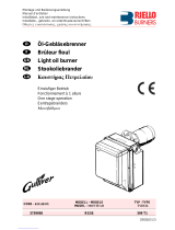
3.4 Burner description
1 Combustion head
2 Ignition electrodes
3 Screw for combustion head adjustment
4 Sleeve
5Fan motor
6 RWF 40 modulator (with analog output 4-20 mA)
7 Fan motor contactor and thermal relay with reset button
8 UV scanner
9 Burner terminal strip “X1”
10 Holes for cables grommets for electrical wirings, accessories
and power supply (to be carried out by the installer)
11 Control box for checking flame and air/fuel ratio
12 Operator panel with LCD display
13 Flame inspection window
14 Low air pressure switch
15 Slide bars for opening the burner and inspecting the combus-
tion head
16 Safety oil solenoid valve
17 Valve assembly with pressure regulator on nozzle return
18 Gas pressure test point and head fixing screw
19 Air pressure test point
20 Air servomotor
21 Pump motor
22 Low oil pressure switch
23 Pilot attachment
24 Pump
25 Gas train flange
26 Boiler mounting flange
27 Flame stability disk
28 Screw securing fan to sleeve
29 Max. gas pressure switch
30 Ignition transformers “T2” (for gas operation)
31 Lifting rings and extention bars
32 Oil/gas actuator
33 High oil pressure switch
34 Ignition transformer “T1” (for oil operation)
35 Terminal strip for oil valve “X2”
36 Timer module and relay “KO1”
37 Timer module and relay “KG1”
38 “K3” relay
39 “K1” relay
40 “KG2” relay
41 “K5” relay
42 “K2” relay
43 Horn
44 Auxiliary fuse
45 “OFF - ON” switch
46 “LOCAL-REMOTE” switch
47 “ALARM SILENCE” button
48 “OIL - OFF - GAS” switch
49 “POWER ON” signal
50 “CALL FOR HEAT signal
51 “ALARM ON” signal
52 “IGNITION ON” signal
53 “FUEL ON” signal
54 Optional holes
55 Ground terminals
56 Pump motor contactor and thermal relay with reset button
57 Delivery oil solenoid valve
58 Return oil solenoid valve
59 DIN bar for fuse holder step-down transformer and OCI
412.10 (available)
Three types of burner failure may occur:
Flame safeguard lock-out
If the flame safeguard alarm 51)(Fig. 1) lights up, it indicates
that the burner is in lock-out. To reset, press the reset push-
button.
Fan motor trip
release by pressing the pushbutton on thermal overload
7)(Fig. 1). See “Thermal relay calibration” on page 28.
Pump motor trip
release by pressing the pushbutton on thermal overload
56)(Fig. 1). See “Thermal relay calibration” on page 28.
1
13
15
22
25 26
28
27
17
33 23
24
2
19
4
36 5
7
8
55
10
12
14 16
3
32
21
29
30
31
11
18
44 34
35
37
38
9
43
39
40
41
42
55
55
56
59
10 57 58
20
45 46 47 49 50
48 54 652 53 54
51
Fig. 1
D11166

Technical description of the burner
9 20043127
GB
3.5 Packaging - weight - Approximate measurements
The burners are skid mounted. Outer dimensions of packaging are
indicated in (Tab. E).
The weight of the burner complete with packaging is indicated in
(Tab. E).
Tab. E
3.6 Burner dimensions
The maximum dimensions of the burners are given in (Fig. 3).
Inspection of the combustion head requires the burner to be
opened and the rear part withdrawn on the slide bars.
The maximum dimension of the burner when open, without casing,
is give in measurement I.
Tab. F
3.7 Standard equipment
Gas train flange . . . . . . . . . . . . . . . . . . . . . . . . . . . . . . . . . . .No. 1
Flange gasket . . . . . . . . . . . . . . . . . . . . . . . . . . . . . . . . . . . . .No. 1
Flange fixing screws. . . . . . . . . . . . . . . . . . . . . . . . . . . . . . . .No. 4
Adaptor G 1/8“ / 1/8“ NPT . . . . . . . . . . . . . . . . . . . . . . . . . . .No. 1
Connector for pilot line . . . . . . . . . . . . . . . . . . . . . . . . . . . . . .No. 1
Seal for adaptor . . . . . . . . . . . . . . . . . . . . . . . . . . . . . . . . . . .No. 1
Instruction booklet . . . . . . . . . . . . . . . . . . . . . . . . . . . . . . . . .No. 1
inch A B C lbs
RLS 70/E 55 33/64“ 30 29/32“ 39 3/8“ 220
Fig. 2
D36
Model ABCDEFGH I LMNO
RLS 70/E 30 5/32" 12 25/32" 17 13/32" 23 15/64" 40 61/64" 9 31/64" 8 19/32" 16 15/16" 63 1/2” 8 25/32” 5 5/8” 8 3/4" 2”
Fig. 3
D2300

20043127 10
GB
Technical description of the burner
3.8 Firing rate
MAXIMUM OUTPUT must be selected in area A (Fig. 4).
MINIMUM OUTPUT must not be lower than the minimum limit
shown in the diagram:
NOTE:
The firing rate area given in Fig. 4 have been reduced by 10% with
respect to the maximum range that can be reached.
3.8.1 Procedure to refer burner operating condition
in high altitude plants
Find the CORRECTED BURNER CAPACITY for the plant’s alti-
tude in chart 1 and the CORRECTED PRESSURE in chart 2.
Check in the firing rate graph of the burner (Fig. 4), if the working
point defined by the values above is within the range limits.
If not, higher burner size is needed.
Note
Charts are based only on altitude variation (reference temper-
ature = 68°F, 20°C)
To get the combined correction in case of different air temper-
ature, a compensation of 1000 ft each 20°F (305 m each
11°C) is applicable (100 ft = 2°F).
Example
Rated capacity = 2500 MBtu/hr - Rated air pressure = 1 “WC
Real altitude = 3000 ft - Real temperature = 88 °F
= 88 °F - 68°F (reference temp.) = 20°F (equiva-
lent 1000 ft variation)
Proceeding as descripted above and considering a “virtual altitude”
of (3000 + 1000) ft:
– the corrected capacity is 2855 MBtu/hr
– the corrected burner air pressure is 1.14
Model MBtu/hr GPH
RLS 70/E 854 6.1
WARNING
The firing rate area values have been obtained con-
sidering an ambient temperature of 68 °F, and an
atmospheric pressure of 394” WC and with the
combustion head adjusted.
Fig. 4
Combustion chamber
pressure - “WC
D11954

Technical description of the burner
11 20043127
GB
CORRECTED BURNER CAPACITY ACCORDING TO ALTITUDE
Altitude
Rated Capacity m a.s.l. 0100 305 610 915 1220 1525 1830 2135 2440
ft a.s.l 0328 1000 2000 3000 4000 5000 6000 7000 8000
500 494 500 512 530 551 571 593 616 641 669
1000 987 1000 1023 1061 1101 1142 1186 1232 1282 1337
1500 1481 1500 1535 1591 1652 1713 1778 1848 1924 2006
2000 1974 2000 2046 2121 2202 2284 2371 2464 2565 2675
2500 2468 2500 2558 2652 2753 2855 2964 3079 3206 3343
3000 2962 3000 3069 3182 3303 3425 3557 3695 3847 4012
3500 3455 3500 3581 3712 3854 3996 4149 4311 4488 4680
4000 3949 4000 4092 4243 4404 4567 4742 4927 5130 5349
4500 4442 4500 4604 4773 4955 5138 5335 5543 5771 6018
5000 4936 5000 5116 5303 5505 5709 5928 6159 6412 6686
5500 5429 5500 5627 5834 6056 6280 6520 6775 7053 7355
6000 5923 6000 6139 6364 6606 6851 7113 7391 7694 8024
6500 6417 6500 6650 6894 7157 7422 7706 8006 8335 8692
7000 6910 7000 7162 7425 7708 7993 8299 8622 8977 9361
7500 7404 7500 7673 7955 8258 8564 8892 9238 9618 10029
8000 7897 8000 8185 8485 8809 9135 9484 9854 10259 10698
8500 8391 8500 8697 9016 9359 9705 10077 10470 10900 11367
9000 8885 9000 9208 9546 9910 10276 10670 11086 11541 12035
9500 9378 9500 9720 10076 10460 10847 11263 11702 12183 12704
10000 9872 10000 10231 10607 11011 11418 11855 12318 12824 13373
Average barometric
pressure (20°C) mbar 1013 1000 977.4 942.8 908.2 875.8 843.5 811.85 779.8 747.8
Average barometric
pressure (68°F) "w.c. 399 394 385 371 358 345 332 320 307 294
CORRECTED BURNER AIR PRESSURE ACCORDING TO ALTITUDE
Altitude
Rated Pressure m a.s.l. 0100 305 610 915 1220 1525 1830 2135 2440
ft a.s.l 0328 1000 2000 3000 4000 5000 6000 7000 8000
0.50 0.49 0.50 0.51 0.53 0.55 0.57 0.59 0.62 0.64 0.67
1.00 0.99 1.00 1.02 1.06 1.10 1.14 1.19 1.23 1.28 1.34
1.50 1.48 1.50 1.53 1.59 1.65 1.71 1.78 1.85 1.92 2.01
2.00 1.97 2.00 2.05 2.12 2.20 2.28 2.37 2.46 2.56 2.67
2.50 2.47 2.50 2.56 2.65 2.75 2.85 2.96 3.08 3.21 3.34
3.00 2.96 3.00 3.07 3.18 3.30 3.43 3.56 3.70 3.85 4.01
3.50 3.46 3.50 3.58 3.71 3.85 4.00 4.15 4.31 4.49 4.68
4.00 3.95 4.00 4.09 4.24 4.40 4.57 4.74 4.93 5.13 5.35
4.50 4.44 4.50 4.60 4.77 4.95 5.14 5.33 5.54 5.77 6.02
5.00 4.94 5.00 5.12 5.30 5.51 5.71 5.93 6.16 6.41 6.69
5.50 5.43 5.50 5.63 5.83 6.06 6.28 6.52 6.77 7.05 7.35
6.00 5.92 6.00 6.14 6.36 6.61 6.85 7.11 7.39 7.69 8.02
6.50 6.42 6.50 6.65 6.89 7.16 7.42 7.71 8.01 8.34 8.69
7.00 6.91 7.00 7.16 7.42 7.71 7.99 8.30 8.62 8.98 9.36
7.50 7.40 7.50 7.67 7.96 8.26 8.56 8.89 9.24 9.62 10.03
8.00 7.90 8.00 8.18 8.49 8.81 9.13 9.48 9.85 10.26 10.70
8.50 8.39 8.50 8.70 9.02 9.36 9.71 10.08 10.47 10.90 11.37
9.00 8.88 9.00 9.21 9.55 9.91 10.28 10.67 11.09 11.54 12.04
9.50 9.38 9.50 9.72 10.08 10.46 10.85 11.26 11.70 12.18 12.70
10.00 9.87 10.00 10.23 10.61 11.01 11.42 11.86 12.32 12.82 13.37
Average barometric
pressure (20°C) mbar 1013 1000 977.4 942.8 908.2 875.8 843.5 811.85 779.8 747.8
Average barometric
pressure (68°F) "w.c. 399 394 385 371 358 345 332 320 307 294
1
2

20043127 12
GB
Technical description of the burner
3.9 Minimum furnace dimensions
The firing rate was set in relation to certified test boilers.
Fig. 5 indicates the diameter and length of the test combustion
chamber.
Example
Output 2576 MBtu/hr: diameter 24 inch - length 6.6 ft.
Fig. 5
Diameter (inches)
Length - ft
Furnace dimensions
D2919

Technical description of the burner
13 20043127
GB
3.10 Control box for the air/fuel ratio (LMV36...)
Warning notes
All activities (mounting, installation and service work, etc.)
must be performed by qualified staff.
Before making any wiring changes in the connection area,
completely isolate the plant from mains supply (all-polar dis-
connection). Ensure that the plant cannot be inadvertently
switched on again and that it is indeed dead. If not observed,
there is a risk of electric shock hazard.
Ensure protection against electric shock hazard by providing
adequate protection for the burner control’s connection termi-
nals.
Each time work has been carried out (mounting, installation,
service work, etc.), check to ensure that wiring and parame-
ters is in an orderly state.
Fall or shock can adversely affect the safety functions. Such
units must not be put into operation, even if they do not exhibit
any damage.
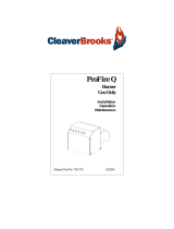
Introduction
The control box for the air/fuel ratio (Fig. 6), (hereafter referred to
simply as the control box), that equips the burners, carries out a se-
ries of integrated functions in order to optimise burner functioning,
both for single operation and together with other units (e.g. double
furnace boiler or more than one generator at the same time).
The basic functions carried out by the control box relate to:
flame control;
the dosage of air and fuel via the positioning (with direct servo-
control) of the relative valves, excluding the possible play in
the mechanical cam calibration systems;
the modulation of burner output, on the basis of the load
requested by the system, maintaining the pressure or temper-
ature of the boiler at the working values set;
the safety diagnostic of the air and fuel circuits, via which it is
possible to easily identify any causes of malfunctioning.
Mechanical design
The following system components are integrated in the LMV36...
basic unit:
• Burner control with gas valve proving system
• Electronic air / fuel ratio control
• Control frequency converter air fan
• Modbus interface
Installation notes
• Always run high-voltage ignition cables separately while ob-
serving the greatest possible distance to the unit and to other
cables.
• Do not mix up live and neutral conductors (fire hazard, danger-
ous failures, loss of protection against electric shock hazard,
etc.).
• Do not lay the connecting cable from the LMV36... to the
AZL2… together with other cables.
Electrical connection of the flame detectors
It is important to achieve practically disturbance- and loss-free sig-
nal transmission:
• Never run the detector cable together with other cables.
– Line capacitance reduces the magnitude of the flame signal.
– Use a separate cable.
• Observe the maximum permissible detector cable lengths.
• The ionization probe is not protected against electric shock
hazard. It is mainspowered and must be protected against ac-
cidental contact.
• Locate the ignition electrode and the ionization probe such that
the ignition spark cannot arc over to the ionization probe (risk
of electrical overloads).
WARNING
To avoid injury to persons, damage to property
or the environment, the following warning notes
must be observed!
The LMV36... is a safety device!
Do not open, interfere with or modify the unit.
The manufacturer will not assume responsibili-
ty for any damage resulting from unauthorized
interference!
WARNING
The first start-up, like every further operation for
the internal settings of the control box, requires
access by means of a password and is only to
be carried out by personnel of the Technical As-
sistance Service who have been specifically
trained in the internal programming of the tool.
Fig. 6
D9300

20043127 14
GB
Technical description of the burner
Technical data
LMV36... basic unit Mains voltage AC 120 V -15 % / +10 %
Mains frequency 50 / 60 Hz ±6 %
Power consumption < 30 W (typically)
Safety class I, with parts according to II and III to DIN EN 60730-1
Terminal loading
‘Inputs’
Unit fuse F1 (internally) 6.3 AT
Perm. mains primary fuse (externally) Max. 16 AT
Undervoltage
• Safety shutdown from operating position
at mains voltage
• Restart on rise in mains voltage
Approx. AC 93 V
Approx. AC 96 V
Terminal loading
‘Outputs’
Total contact loading:
• Nominal voltage
• Unit input current (safety loop) from:
- Fan motor contactor
- Ignition transformer
- Valves
- Oil pump / magnetic clutch
AC 120 V, 50 / 60 Hz
Max. 5 A
Individual contact loading:
Fan motor contactor
• Nominal voltage
• Nominal current
• Power factor
AC 120 V, 50 / 60 Hz
1.6 A pilot duty load declaration to UL372
cos > 0.4
Alarm output
• Nominal voltage
• Nominal current
• Power factor
AC 120 V, 50 / 60 Hz
1 A
cos > 0.4
Ignition transformer
• Nominal voltage
• Nominal current
• Power factor
AC 120 V, 50 / 60 Hz
1.6 A pilot duty load declaration to UL372 or 250 VA ignition
load declaration to UL372
cos > 0.2
Fuel valves
• Nominal voltage
• Nominal current
• Power factor
AC 120 V, 50 / 60 Hz
1.6 A pilot duty load declaration to UL372
cos > 0.4
Operation display
• Nominal voltage
• Nominal current
• Power factor
AC 120 V, 50 / 60 Hz
0.5 A
cos > 0.4
Cable lengths Mains line
Display, BCI
External lockout reset button
Max. 100 m (100 pF/m)
For used outside the burner cover or the control panel:
Max. 3 m (100 pF/m)
Max. 20 m (100 pF/m)
Environmental
conditions
Operation
Climatic conditions
Mechanical conditions
Temperature range
Humidity
DIN EN 60721-3-3
Class 3K3
Class 3M3
-20...+60 °C
< 95 % r.h.

Technical description of the burner
15 20043127
GB
Operation sequence of the burner
Legend to the sequence diagrams:
Valve proving takes place depending on the parameter:
2) Only with valve proving on startup
3) Parameter: with/without alarm in the event of start prevention
4) In the event of an erroneous signal on startup, followed by
phase 10, otherwise phase 70
0° Position as supplied (0°)
90° Actuator fully open (90°)
Assignment of times:
t1 Prepurge time
TSA1 Safety time 1 gas / oil
TSA2 Safety time 2 gas / oil
00 02 12 22 24 30 36 38 40 42 44 50 52 60 62 70 72 74 81 82 8380
3)
4)
2)
TSA1 TSA2
t1
90
p
a
T
P
P
T
P
10
Shutdown
Operation
Startup Valve proving
OUTPUTS INPUTS
Phase number
Fuel
Actuator 2
Air
Actuator 1
Actuators
Safety limit thermostat (STB)
Control thermostat or pressurestat (R)
Flame signal (FS)
Air pressure switch (LP)
Pressure switch-min (Pmin)
Pressure switch-max (Pmax)
Valve proving / leakage test (P LT)
POC (alternative to Pmax)
No-load position
Ignition load
Postpurge position
Nominal load
Low-fire
90°
0°
VSD
Motor (M)
Ignition transformer (Z)
Alarm (AL)
Safety valve (SV)
Fuel valve 1 (V1)
Fuel valve 2 (V2)
Pilot valve (PV)
No-load position
Ignition load
Postpurge position
Nominal load
Low-fire
90°
0°
No-load position
Ignition load
Postpurge position
Nominal load
Low-fire
90°
0°
Fig. 7
D9288
Signal ON
Signal OFF
Any signal is allowed
In standby: after referencing, the actuator is driven to the
no-load position

20043127 16
GB
Technical description of the burner
3.11 Actuators (SQM33.5...)
Warning notes
All activities (mounting, installation and service work, etc.)
must be performed by qualified staff.
Before making any wiring changes in the connection area of
the units, completely isolate the equipment from mains supply
(all-polar disconnection). If not observed, there is a risk of
electric shock hazard.
Ensure protection against electric shock hazard by providing
adequate protection for the connection terminals and by
securing the housing cover.
After any kind of activity (mounting, installation and service
work, etc.), check wiring.
Also ensure that the parameters are correctly set.
Fall or shock can adversely affect the safety functions. Such
units must not be put into operation, even if they do not exhibit
any damage.
Use
The actuators (Fig. 8) are used to drive and position the air damper
and the gas butterfly valve, without mechanical leverages but via
the interposition of an elastic coupling.
They are commanded by the control box, which constantly checks
their position by means of a return signal from the optic sensor in-
side the actuator.
The position (in degrees) of the actuators can be seen on the dis-
play of the Operator Panel.
Index “0” for fuel actuator, index “1” for air actuator.
Installation notes
• Always run the high-voltage ignition cables separate from the
unit and other cables while observing the greatest possible dis-
tance.
• The holding torque is reduced when the actuator is disconnect-
ed from power.
Technical data
WARNING
To avoid injury to persons, damage to property
or the environment, the following warning notes
should be observed!
Do not open, interfere with or modify the actua-
tors!
WARNING
The actuator’s housing must not be opened.
The actuator contains an optical feedback sys-
tem.
WARNING
When servicing or replacing the actuators, take
care not to invert the connectors.
Operating voltage AC / DC 24 V ±20 %
(load on interface)
Safety class 2 to EN 60 730 part 1 and parts 2…14
Power consumption max. 10 W
Degree of protection IP54 to EN 60 529-1
Opening time 0 - 90° min: 5s, max.: 120s
(depending on the type of control box)
Firing rate 0 - 90°
Cable connection RAST2,5 connectors
Direction of rotation Clockwise/anticlockwise
(can be selected from the control box)
Nominal output torque 3 Nm
Holding torque
(when live) 3 Nm
Holding torque
(when dead) 2.6 Nm
Weight approx. 1 kg
Environmental conditions:
Operation
Climatic conditions
Mechanical conditions
Temperature range
Humidity
DIN EN 60 721-3-3
class 3K5
class 3M4
-20...+ 60 °C
< 95 % r.h.
D8271
Fig. 8

Installation
17 20043127
GB
4.1 Notes on safety for the installation
After carefully cleaning all around the area where the burner will
be installed, and arranging the correct lighting of the environ-
ment, proceed with the installation operations.
4.2 Handling
The packaging of the burner includes a wooden platform, so it is
possible to move the burner (still packaged) with a transpallet truck
or fork lift truck.
With regard to the transport in the obligatory passages, refer to
the overall dimensions shown in Fig. 3.
Check also that the area in which you are working is empty and that
there is an adequate escape area (i.e. a free, safe area to which
you can quickly move if the burner should fall).
During the handling, keep the load at not more than 10” from the
ground.
4.3 Preliminary checks
Checking the consignment
4.4 Boiler plate
Drill the combustion chamber mounting plate as shown in (Fig. 9).
The position of the threaded holes can be marked using the gasket
supplied with the burner.
4 Installation
DANGER
All the installation, maintenance and disassembly
operations must be carried out with the electricity
supply disconnected.
WARNING
The installation of the burner must be carried out by
qualified personnel, as indicated in this manual and
in compliance with the standards and regulations of
the laws in force.
WARNING
The handling operations for the burner can be high-
ly dangerous if not carried out with the greatest at-
tention: keep any unauthorised people at a
distance; check the integrity and suitableness of the
available means of handling.
CAUTION
After positioning the burner near the installation
point, correctly dispose of all residual packaging,
separating the various types of material.
Before proceeding with the installation operations,
carefully clean all around the area where the burner
will be installed.
CAUTION
After removing all the packaging, check the integrity
of the contents. In the event of doubt, do not use the
burner; contact the supplier.
The packaging elements (wooden cage or card-
board box, nails, clips, plastic bags, etc.) must not
be abandoned as they are potential sources of dan-
ger and pollution; they should be collected and dis-
posed of in the appropriate places.
WARNING
The output of the burner must be within the boiler's
firing rate;
WARNING
A burner label that has been tampered with, re-
moved or is missing, along with anything else that
prevents the definite identification of the burner
makes any installation or maintenance work diffi-
cult.
inch A B C
RLS 70/E 9 1/16“12 25/32“ - 14 1/2“5/8 W
Fig. 9
D455

20043127 18
GB
Installation
4.5 Burner raising
In order to lift the burner, proceed as follows:
screw the two extension bars 1) on the pins 2) (Fig. 10);
place the two plates 3) fix them on the relevant ring nuts 4);
The four burner lifting points are indicated in Fig. 10.
4.6 Blast tube length
The length of the blast tube must be selected according to the indi-
cations provided by the manufacturer of the boiler, it must be great-
er than the thickness of the boiler door complete with its insulation.
The range of lengths available, L (inch), is as follows:
For boilers with front flue passes 13) or flame inversion chambers,
insulation material 11) must be inserted between the refractory 12)
and the blast tube 10).
This protective insulation must not compromise the extraction of
the blast tube. For boilers having a water-cooled front, the insula-
tion 11)-12) (Fig. 11) is not required unless it is required by the boil-
er manufacturer.
4.7 Securing the burner to the boiler
Detach the combustion head from the burner, (Fig. 11):
disconnect the oil pipes by unscrewing the two connectors 6);
loosen the 4 screws 3) and remove the cover 1);
disengage the swivel coupling 14) from the graduated sector;
remove the screws 2) from the slide bars 5);
remove the 2 screws 4) and pull the burner back on slide bars
5) by about 4”;
install the extension bars 31) Fig. 1, page 8 and re-screw the
screws 2) including the safety plate 15);
disconnect the electrode wires and then pull the burner com-
pletely off the slide bars.
WARNING
The manufacturer declines any and every respon-
sibility for any possible lifting movements, different
from those indicated in this manual.
12
3
4
Fig. 10
D10111
Model L
RLS 70/E 9 3/16”
4"
125
3
7
9
13
L
11
12
14
8
4
15
6
10
Fig. 11
D11001
/