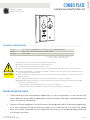
BEA KEYSWITCHES are versatile devices that combine a keyswitch with a push plate switch, offering various functionalities for controlling door systems. With their SPST (Single Pole Single Throw) configuration, these keyswitches provide maintained or momentary contact options, depending on the model chosen. The push plate switch features a Cherry switch with momentary contact and a high current rating of 15A at 125 VAC, making it suitable for demanding applications. The compact design with dimensions of 4 1/2" × 4 1/2" allows for easy installation in standard double-gang electrical boxes.
BEA KEYSWITCHES are versatile devices that combine a keyswitch with a push plate switch, offering various functionalities for controlling door systems. With their SPST (Single Pole Single Throw) configuration, these keyswitches provide maintained or momentary contact options, depending on the model chosen. The push plate switch features a Cherry switch with momentary contact and a high current rating of 15A at 125 VAC, making it suitable for demanding applications. The compact design with dimensions of 4 1/2" × 4 1/2" allows for easy installation in standard double-gang electrical boxes.


-
 1
1
-
 2
2


BEA KEYSWITCHES User guide
- Type
- User guide
- This manual is also suitable for
BEA KEYSWITCHES are versatile devices that combine a keyswitch with a push plate switch, offering various functionalities for controlling door systems. With their SPST (Single Pole Single Throw) configuration, these keyswitches provide maintained or momentary contact options, depending on the model chosen. The push plate switch features a Cherry switch with momentary contact and a high current rating of 15A at 125 VAC, making it suitable for demanding applications. The compact design with dimensions of 4 1/2" × 4 1/2" allows for easy installation in standard double-gang electrical boxes.
Ask a question and I''ll find the answer in the document
Finding information in a document is now easier with AI