Page is loading ...

75.5753.18 LZR-MICROSCAN T 20200312 Page 1 of 16
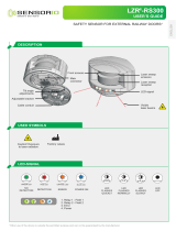
LZR-MICROSCAN T
2
1
3
5
4
8
9
6
7
75.5753.18 LZR-MICROSCAN T 20200312 Page 1 of 16
ENGLISH
1. Tilt adjustment
2. Sensor connection ports
3. Sensor LED
green = operational
red = in detection/monitoring
orange = error (reference hub LCD)
4. End caps
5. Optical window
6. Plug-and-Play ports
7. Adjustment knob
8. LCD
9. Hub LEDs
TEACH-IN: Teach-in in progress or required
HOME: Door(s) closed
TRACKING: Door position / Detection zone tracking
Stand-Alone, Door-Mounted, Safety Sensor
System for Automatic Swing Doors
(US version)
Visit website for
available languages
of this document.

Page 2 of 16 75.5753.18 LZR-MICROSCAN T 20200312Page 2 of 16 75.5753.18 LZR-MICROSCAN T 20200312
BEA, Inc., the sensor manufacturer, cannot be held responsible for incorrect installations or inappropriate adjustments of the sensor/device; therefore,
BEA, Inc. does not guarantee any use of the sensor outside of its intended purpose.
BEA, Inc. strongly recommends that installation and service technicians be AAADM-certifi ed for pedestrian doors, IDA-certifi ed for doors/gates, and
factory-trained for the type of door/gate system.
Installers and service personnel are responsible for executing a risk assessment following each installation/service performed, ensuring that the sensor
system installation is compliant with local, national, and international regulations, codes, and standards.
Once installation or service work is complete, a safety inspection of the door/gate shall be performed per the door/gate manufacturer recommendations
and/or per AAADM/ANSI/DASMA guidelines (where applicable) for best industry practices. Safety inspections must be performed during each service
call – examples of these safety inspections can be found on an AAADM safety information label (e.g. ANSI/DASMA 102, ANSI/DASMA 107).
Verify that all appropriate industry signage and warning labels are in place.
BEA, INC. INSTALLATION/SERVICE COMPLIANCE EXPECTATIONS
Technology: laser, time-of-flight measurement
Detection mode: presence
Detection width: 20 – 48” (measured from leading edge to sensor LED)
Mounting Height: 75 – 98” (measured from finished floor to sensor LED)
Remission factor: > 2%
Angular resolution: 2.56°
Testbody: 28” (H) x 12” (W) x 8” (D)
Emission characteristics:
IR laser: wavelength 905 nm; max. output pulse power 35 W (CLASS 1)
Supply Voltage: 12 – 30 VDC (15 W Class II)
Power Consumption: < 15 W
Response time: typ. 40 ms (max. 80 ms)
Output:
Rating:
4 electro-mechanic relays (galvanic isolated - polarity free)
All outputs Class 2 supply, 12 – 24 VAC / 12 – 30 VDC, max. 15 W
Test:
Rating:
2 optocouplers (galvanic isolated – polarity-free)
12 – 30 VDC, max. 15 W
Temperature Range: -13 – 121 °F (-25 – 55 °C)
Degree of Protection: Hub: IP20/NEMA 1
Sensor: IP53/NEMA 3
Humidity: 0 – 95% non-condensing
Vibrations: < 2 G
Material: PC/ASA
Norm Conformity: EN 60825-1-Eye-safety class 1 IR laser (905 nm), UL60730
UL10B/C fire-rated 3 hours (file #R39071)
Mounting angle (rotational): 35° fixed
Tilt angle: 0 – 5° (for angles less than 5°, contact Tech Support)
Pollution on front screens: max. 30%; homogenous
Specifications are subject to change without prior notice.
All values have been measured in specific conditions.
TECHNICAL SPECIFICATIONS
For version compatibiltiy serial number information, please see Application Note 76.0017 or contact BEA for technical support.

75.5753.18 LZR-MICROSCAN T 20200312 Page 3 of 1675.5753.18 LZR-MICROSCAN T 20200312 Page 3 of 16
CLASS 1
LASER PRODUCT
!
CAUTION
IR laser (Class 1)
wavelength 905 nm
max. output pulse power 35 W
CAUTION: Use of controls or adjustments or
performance of procedures other than those specified
herein may result in hazardous radiation exposure.
PRECAUTIONS
GENERAL INSTALLATION TIPS
Shut off all power going to header before attempting any wiring procedures.
Maintain a clean and safe environment when working in public areas.
Constantly be aware of pedestrian traffic around the door area.
Always stop pedestrian traffic through the doorway when performing tests that may result in unexpected reactions by
the door.
ESD (electrostatic discharge): Circuit boards are vulnerable to damage by electrostatic discharge. Before handling any
board, ensure you dissipate your body’s ESD charge.
Always check placement of all wiring before powering up to ensure that moving door parts will not catch any wires and
cause damage to equipment.
Ensure compliance with all applicable safety standards (i.e. ANSI A156.10) upon completion of installation.
DO NOT attempt any internal repair of the components. All repairs and/or component replacements must be performed
by BEA, Inc. Unauthorized disassembly or repair:
1. May jeopardize personal safety and may expose one to the risk of electrical shock.
2. May adversely affect the safe and reliable performance of the product resulting in a voided warranty.
◊ Avoid extreme vibrations.
◊ Avoid moving objects, light sources, and highly reflective objects in detection zone.
◊ Do not cover the sensor.
◊ Always test the proper operation of the installation before leaving the premises.
◊ The door control unit and the door header must be correctly grounded.
◊ Only trained and qualified personnel are recommended to install and set up the sensor.
◊ The warranty is void if unauthorized repairs are made or attempted by unauthorized personnel.
LZR-MICROSCAN T sensors are intended to be used with PEDESTRIAN, SWING-DOOR systems.
READ BEFORE BEGINNING INSTALLATION/PROGRAMMING/SET-UP
- It is recommended to clean the optical parts at least once per year or more if required due to
environmental conditions.
- Do not use abrasive cleaning components.
MAINTENANCE

Page 4 of 16 75.5753.18 LZR-MICROSCAN T 20200312Page 4 of 16 75.5753.18 LZR-MICROSCAN T 20200312
* SURVEY THE DOOR:
- Verify that the door control and operator is functional and operational before beginning.
- Check BOTH sides of the door for the following: distance from pivot edge, distance from the top of
the door, frame clearance, finger guard, door arm, etc. Check that the location is clear and free of any
obsutrctions.
* SENSOR LOCATION IS IMPORTANT: It is best practice to mount the sensors as close to the top of the door.
Mounting height from finished floor to the sensor LED must be within the range of 75" to 98".
* USE A SPACER, IF NECESSARY: Be sure to use a spacer when door hardware extends across the width of the
door and is more than 2 inches thick.
* USE A MOUNTING ARM, IF NECESSARY: Be sure to use the Mounting Arm kit when mounting on a narrow-
style aluminum door. Refer to Mounting Template 75.5908 when using the Mounting Arm kit.
* HOLE SIZE: Be sure to comply with hole sizes called out on the Mounting Template.
* LZR-MICROSCAN T SENSORS AND MOUNTING ARM ACCESSORIES ARE HANDED. PLEASE OBSERVE
WHEN MOUNTING.
A) INSTALL MOUNTING ACCESSORIES (IF REQUIRED)
NOTES
I. INSTALLATION
• If a mounting arm is needed for this application, align the Mounting Template (75.5908) in the desired
location, and mark and drill the required holes.
» If a spacer is also required for this application, secure the spacer to the mounting arm, and then
secure the sensor to the spacer.
» If no spacer is required for this application, simply secure the sensor directly to the mounting arm.
• If a spacer only is required for this application, mark and drill the SPACER MOUNTING HOLES on
Mounting Template (75.5754), and then simply secure the sensor directly to the spacer using the
SENSOR MOUNTING HOLES.
IMPORTANT:
• All wiring harnesses used must a) be routed separate from any mains or non-class 2 voltage
cables, or b) be rated for the mains voltage and suitable protection.
• Routing means must be used in accordance with national and local codes.
mounting arm spacer mounting arm with spacer

75.5753.18 LZR-MICROSCAN T 20200312 Page 5 of 1675.5753.18 LZR-MICROSCAN T 20200312 Page 5 of 16
B) PREPARE THE MOUNTING LOCATION
C) MOUNT SENSORS
1) If mounting the sensor directly to the door, align the Mounting Template (75.5754) in the desired location.
2) Mark and drill holes identified on the Mounting Template. Also mark and drill the Door Loop hole and
wire passage hole in the header and door jamb (
1
⁄2").
3) Repeat these steps on the other side of the door using the opposite side of the Mounting Template.
4) Determine which sensor is to be mounted on the Door Loop side of the door and remove the blank end
cap from the side of the sensor which will receive the Door Loop.
5) Run the Slave Sensor Harness (P/N 35.1327) through the pre-drilled wire passage hole.
1) Mount the Slave Sensor and plug in the Slave Sensor Harness into the uppermost port on the Slave Sensor.
2) Route the Master Sensor Harness (P/N 35.1326) from the header, into the door jamb, and through the
pre-drilled Door Loop hole.
3) Shorten the Door Loop as much as necessary to avoid the Loop obstructing the detection zone. Pass the
Master Sensor Harness through the Door Loop, and then secure the Door Loop using the Jamb Cap Kit.
Pull extra harness slack through the Door Loop (away from sensor) before tightening the end cap screws.
4) Plug the Master Sensor Harness into the Master Sensor at the closest port and then mount the Master
Sensor to the door.
5) Plug the Slave Sensor Harness into the uppermost port on the Master Sensor.
6) Secure the Door Loop to the Master Sensor using the end cap and screws provided.
IF NECESSARY, REPEAT THIS SECTION FOR A SECOND DOOR LEAF.
I. INSTALLATION (cont.)
DO NOT APPLY COVERS UNTIL THE SYSTEM IS FULLY OPERATIONAL.

Page 6 of 16 75.5753.18 LZR-MICROSCAN T 20200312Page 6 of 16 75.5753.18 LZR-MICROSCAN T 20200312
HUB
Home
Switch
HUB
Home
Switch
Home
Switch
NORMAL WIRING
for single doors
WIRING IN SERIES
for simultaneous pairs or dual-egress pairs
I. INSTALLATION (cont.)
E) INSTALL HOME SWITCH
1) Install the hub in the door header. Ensure that it is centered and in a location which is easily accessible.
2) Plug the Master Sensor Harness into the hub port labeled Door A Sensors. See table below for more
information on how to use hub ports depending on door type.
3) If a second door leaf is being used for this system, plug that Master Sensor Harness into Door B
Sensors.
4) Plug the System Harness (P/N 20.5304) into the hub port labeled System.
1) Install Home Switch in the desired location.
2) Wire-nut accordingly the white Home Switch wires to the orange
and orange/black System Harness wires (plugged into hub).
For simultaneous pairs or dual-egress doors, two (2) Home
Switches must be wired in series with orange and orange/black
wires of System Harness plugged into hub.
DOOR
TYPE
DOOR
CONTROLS
HUB PORT
single 1 always use DOOR CONTROL A hub port
simultaneous
pair*
2
from header cover side, left door uses DOOR CONTROL A hub port and right
door uses DOOR CONTROL B hub port
dual-egress* 2
from header cover side, whichever door is pushed (right door) during Teach-In
process uses DOOR CONTROL B hub port
* When only one door control is used for pairs, refer to instructions for "single".
Any dry-contact Home Switch or auxiliary switch may be used and must be closed when door is closed.
D) INSTALL HUB

75.5753.18 LZR-MICROSCAN T 20200312 Page 7 of 1675.5753.18 LZR-MICROSCAN T 20200312 Page 7 of 16
All white wires (white, white/black, white/red)
are always used.
For each function (activation, safety, stall), either
green or yellow are used - not both.
PLUG
GREEN
YELLOW
WHITE
GREEN/BLACK
YELLOW/BLACK
WHITE/BLACK
GREEN/RED
YELLOW/RED
WHITE/RED
F) CONNECT HUB TO DOOR CONTROL
1) Plug the Door Control Harness (P/N 20.5222) into the hub port labeled Door Control A.
2) Wire the Door Control Harness to the door control. See wiring diagram below for wire function
descriptions. Also see the "General Door Control Wiring Matrix for Swing Doors" Application Note
(76.0031) for more information regarding specific door controls.
3) Repeat these steps with a second Door Control Harness if installing on a simultaneous pair or a dual-
egress pair which utilizes two door controls.
IF NECESSARY, REPEAT THIS SECTION FOR A SECOND DOOR CONTROL.
I. INSTALLATION (cont.)
EXTERNAL MONITORING
LZR-MICROSCAN T hub/sensors are intended to be monitored by the door system (see Application Note #31, 76.0031). If the door
control does not utilize monitoring, do not use monitoring wires.
When utilizing monitoring, the sensor LED will briefly flash RED during monitoring communication with door control. This indicates
that external monitoring is functional. Monitoring functionality must be active on the sensor and door control, and monitoring
wires must be properly connected to the door control.
ACT N.O.
ACT N.C.
ACT COM.
SAFE N.O.
SAFE N.C.
SAFE COM.
STALL N.O.
STALL N.C.
STALL COM.

Page 8 of 16 75.5753.18 LZR-MICROSCAN T 20200312Page 8 of 16 75.5753.18 LZR-MICROSCAN T 20200312
H) CONNECT TO POWER
G) CONNECT ADDITIONAL SYSTEM DEVICES
1) Refer to "General Door Control Wiring Matrix for Swing Doors"
Application Note (76.0031) for power supply to be used per the
given door control.
2) Wire power supply:
• If using a BEA power supply, remove the plug from
the Power Supply Harness (P/N 20.5095) and strip the
wires. Then, wire-nut the power supply input to a 110
V power source.
• If utilizing door control power, simply connect the Power Supply Harness to the door control.
3) Plug Power Supply Harness into hub port labeled Power.
1) Install an ON / OFF / HOLD OPEN Switch, if desired.
2) Plug the switch harness into the hub port labeled On / Off /
Hold Open.
If an ON / OFF / HOLD OPEN Switch already exists, wire-nut
the red and black wires together (or splice existing switch into
jumper) after plugging the harness into the hub.
3) Install necessary activation devices (e.g. EAGLE, PUSH PLATE) and
wire accordingly (see below, right).
COM
NO
Push
Plate
Harness
I. INSTALLATION (cont.)
LZR-MICROSCAN T hub/sensors must be powered by a UL Class 2 power supply limited to 15 W.
If a NEMA 5-15R outlet is not available in door header, cut off NEMA 5-15P plug and wire-nut to 110 VAC
observing polarity and grounding.
ON / OFF / HOLD OPEN Switch installed
Plug EAGLE Harness (P/N 20.5096) into Motion 1.
Wire Push Plates to System Harness (gray wires).
Wire Logic Modules to Door Control
Harness (activation wires).
see previous page
FUNCTION JUMPER WIRES
on red jumped to black
off none
hold open black jumped to white

75.5753.18 LZR-MICROSCAN T 20200312 Page 9 of 1675.5753.18 LZR-MICROSCAN T 20200312 Page 9 of 16
If the door control utilizes monitoring, monitoring must be turned off in the door control as
well as the LZR-MICROSCAN hub prior to the Teach-In.
How to navigate through the LCD menu:
- Push the gray adjustment knob to enter
the LCD menu.
- Select your language before entering
the first LCD menu. This is available for
the first 30 seconds after power-on of
the hub.
- Scroll through the menu items using
the adjustment knob and push to make
selections.
How to read the LCD:
- Act = Activation
Saf = Safety
S1 = Stall (door 1)
S2 = Stall (door 2)
- When a parameter is
highlighted, that is the active
output.
The opposite indicates reverse
logic.
- Factory Value
II. PROGRAMMING
SELECT
SCROLL
NOTES
1) Program the hub according to desired settings.
MENU1 (BASIC menu) items MUST be programmed (see page 11).
2) The network icon will appear for approximately five seconds and then it will return to the Teach-in
screen. The hub LED will display flashing blue and solid orange, and the sensor LED will display flashing
red/green.
CAUTION: No safety present during Teach-in cycle.
3) Verify that the Home Switch is making/breaking within a few degrees of door movement by observing
the orange hub LED. The Home Switch sensitivity should be set as high as possible.
4) Push and hold the adjustment knob for three seconds until the blue LED begins flashing. Follow
instructions on the screen, observing the countdown.
5) For dual-egress doors, push the right door (Door B) open at least 10 degrees when prompted.
continued on next page

Page 10 of 16 75.5753.18 LZR-MICROSCAN T 20200312Page 10 of 16 75.5753.18 LZR-MICROSCAN T 20200312
II. PROGRAMMING (cont.)
Be sure to walk-test door after set-up is complete and perform new Teach-in anytime door operator,
control, sensor, or hub is adjusted.
Once the Teach-In process is complete, monitoring must be turned on, if applicable.
TEACH-IN STAGE LCD HUB LED SENSOR LED
a) Door Closed Teach-in
b) Door Opening Teach-in (door
will open automatically)
c) Door Open Teach-in
d) Door Closing Teach-in (door
will close automatically)
e) Teach-in data saving
f) Restarting (hour glass icon
displays for approximately 30
seconds)
g) Returns to home screen
(teach-in complete)
HUB LED
COLOR SIGNAL DESCRIPTION
Blue Teach-in Teach-in in progess or Teach-in required
White Tracking Door position & detection zone tracking
Orange Home Switch Home Switch closed (door/doors closed)
SENSOR LED
COLOR SIGNAL DESCRIPTION
Green Operational Sensor operational
Red Detection Sensor in detection / Sensor monitoring
Orange* Error Sensor in error...reference hub LCD
* see TROUBLESHOOTING section for descriptions of orange LED error indications
6) Teach-In will begin automatically:
LED INDICATIONS AFTER LEARN

75.5753.18 LZR-MICROSCAN T 20200312 Page 11 of 1675.5753.18 LZR-MICROSCAN T 20200312 Page 11 of 16
OVERVIEW OF SETTINGS
MENU
ConfiLCD
DISPLAY
PARAMETERS DESCRIPTION
Menu 1 (BASIC)
DoorType
Undefined
Single
Pair
DualEgr
InDualEgr
Type of door system on which sensors are installed:
Single: Single Door Pair: Pair of Doors
DualEgr: Dual-egress Doors InDualEgr: Independent Dual-egress Doors
DetectZoneA
1
20 – 48 Distance (in inches) from sensor LED to leading edge of Door A [round down]
DetectZoneB
1
20 – 48 Distance (in inches) from sensor LED to leading edge of Door B [round down]
Guiderail 0 – 60 Guiderail height from floor (in inches)
Menu 2 (ADVANCED)
Monitoring
2
Off
Safe
Stall
Safe&Stall
Act
Act&Stall
Type of monitoring:
Off: No Monitoring Safe: Monitoring of Safety Signal
Stall: Monitoring of Stall Signal Safe&Stall: Monitoring of Safety & Stall Signals
Act: Monitoring of Activation Signal Act&Stall: Monitoring of Activation & Stall Signals
KnowingAct Off On Turns Knowing Act Off or On
Act:HoldTime 1 - 5 - 30 Time activation relay will be held after loss of detection (in seconds)
PushNGo Off On Turns Push-And-Go Off or On
NotCloseTime 5 - 10 - 30 Time required for door to reach “Closed” from “Open” or “Manual” before switching to “NotClosed” (in seconds)
AdvanceSafe Off On
Type of safety provided while door(s) is/are currently open due to manual operation (or stack pressure):
Off: Allows door(s) to activate, via motion sensor or push plate
On: Prevents door(s) from activating, via motion sensor or push plate
Act:Dist
3
12 - 24 - 48 Door closed detection distance of Approach Sensor(s) (in inches)
MonitorLogic
2
ActiveLow
ActiveHigh
ActiveLow: 0V requests monitoring
ActiveHigh: > 0V requests monitoring
Safe:Dist
3
Deep
Medium
Limited
Door closed detection distance of Safety Sensor(s):
Deep: 4 curtains Medium: 3 curtains Limited: 2 curtains
Traffic
Normal
High
Extreme
When doors do not come closed for a certain period of time due to traffic flow
Normal: ≤ 5 min High: ≤ 30 min Extreme: > 30 min
Default parameters are in BOLD. Menu 1 (Basic) items MUST be programmed.
NOTES:
1. Detection zone “A” and “B” are the sensor pattern width and are determined by measuring the distance from the sensor LED to the leading edge of the door.
2. The sensor LED will briefly flash RED during monitoring communication with door control. This indicates that external monitoring is functional. Monitoring functionality must be active on the sensor
and door control, and monitoring wires must be properly connected to the door control.
3. The Approach Side Detection Zone (Act:Dist) and Swing Side Safety Zone (Safe:Dist) are independently adjustable.

Page 12 of 16 75.5753.18 LZR-MICROSCAN T 20200312Page 12 of 16 75.5753.18 LZR-MICROSCAN T 20200312
NOTES:
4. Display Door (DispDoor): Displays current position / state of doors.
5. Display Sensor (DispSens): Displays which device(s) are active.
6. Display Position (DispPos): Displays opening position (0% = full closed, 100% = full open relative to teach-in open cycle.
7. If experiencing issues, reset error log and review at a later time for possible new error(s) to help solve the issue.
OVERVIEW OF SETTINGS (cont.)
MENU
ConfiLCD
DISPLAY
PARAMETERS DESCRIPTION
Menu 3 (DIAGNOSTICS)
DispDoor
4
Closed
Opening
Open
Closing
NotClosed
Manual
HoldOpen
Off
AdvanceSafe
Displays current position/state of door
DispSens
5
A1
A2
PP
MO
S1
S2
HM
Displays active devices
A1: Approach MICROSCAN T 1 MO: Motion Sensor S2: Safety MICROSCAN T 2
A2: Approach MICROSCAN T 2 S1: Safety MICROSCAN T 1 HM: Home Switch Closed
PP: Push Plate
DispPos
6
% % Displays opening position (0% = full closed, 100% = full open relative to teach-in cycle)
ID# ......................
Config ......................
Software ......................
ErrorLog ......................
ZIP ......................
HubTemp ......................
PowerSupply ......................
OperatingTime ......................
ResetLog
7
......................
Admin ......................
Network ......................
unique ID number
configuration part number
software part number
last 20 errors
all parameter settings in zipped format
operating temperature of hub
supply voltage at power connector
power duration since first start-up
delete all saved errors
enter code (1234) to access admin mode
Act:Uncover (3 – 12, default 4)
Saf:Uncover (3 – 12, default 4)
AutoLRNTime (30, 60, 90, 120, infinite)
RelayLogic (DeEngergized, Energized)
Boundary (on, off)
FactoryRst (no, yes)
sensor info: software, configuration, mounting location

75.5753.18 LZR-MICROSCAN T 20200312 Page 13 of 1675.5753.18 LZR-MICROSCAN T 20200312 Page 13 of 16
Hub LCD is not on No input power Verify power supply connection.
Bad power Verify power supply. Power from BEA power supply.
Faulty hub Replace hub.
No “CLEAR AREA”
during setup
Sensors not discovered Verify sensor harness connection.
No Floppy Disk after
setup
Teach-in failed Perform new Teach-in.
Verify Home Switch is functioning properly.
Door(s) will not open/
close
Door control issue Verify door control is operational with nothing wired to it.
No inputs/outputs connected Verify all connections are secure (sensors and On/Off/Hold
Open switch must be connected).
Knowing Act turned on Turn Knowing Act off or use Knowing Act devices.
Incorrect wiring Verify wiring from hub to door control.
Incorrect monitoring settings
or wiring
Verify monitoring settings and wiring.
Door(s) keep recycling
(ghosting)
Approach-side sensors going
into detection
Adjust approach-side sensors Activation Distance and/or
motion sensor.
Home Switch not “making”
at door-closed
Adjust Home Switch and verify proper wiring.
Cap LCD screen Teach-in required Perform re-Teach-in.
Orange flashing LED
on Sensor - reference
Hub for error
height/angle Sensor mounted too high or adjusted too close to door.
Verify handedness (right- or left-handed) for correct
orientation.
EDPS Door did not open or reach full-open during Teach-in.
BUS config Number of doors configured incorrectly.
boundary Sensor masked by foreign object.
lost message Loose or broken sensor harness.
Door never reaches
“Hold Open” or “Off”
states
Not using On / Off / Hold
Open Switch
Wire existing On / Off / Hold Open switch to jumper or
plug BEA On / Off / Hold Open Switch into hub.
Hub Environment error Voltage too high/low Verify power supply voltage, power from BEA power
supply.
Temperature too high/low Envionment may be too cold/hot for hub operation.
Visible Monitoring
indication LED does
not flash.
Monitoring installation/set-
up error.
Verify door control is capable of monitoring and the sensor
monitoring wires are properly connected to the door
control.
Verify monitoring is active in the sensor settings (high/low
for each door control).
Sensor and/or wiring
malfunction.
Verify wiring. If still unresolved, replace the sensor.
Visible Monitoring
Indication LED flashes
continuously
Monitoring installation /
set-up error
Verify door control is capable of monitoring and sensor
monitoring wires are properly connected to control.
Wiring malfunction Verify that there are no breaks anywhere in the wire
harness.
Door control does not utilize
monitoring
Turn monitoring off in the hub (Menu 2 – ADVANCED).
TROUBLESHOOTING
Troubleshooting tools can be viewed on Hub LCD within Menu 3 (DIAGNOSTICS).
General

Page 14 of 16 75.5753.18 LZR-MICROSCAN T 20200312Page 14 of 16 75.5753.18 LZR-MICROSCAN T 20200312
TROUBLESHOOTING (cont.)
most common Sensor mounted too low/high Mounting height (from floor to sensor LED):
min: 6’3” (75”)
max: 8’2” (98”)
(review mounting template)
Sensor mounted incorrectly in relation to
RH and LH mount
Position arrow on sensor to point towards jamb.
Sensor mounting angle out of
tolerance
Correct the mounting angle: 35 (±5)°
(review mounting template)
Sensor tilt angle too close to the door Tighten tilt angle screw
Sensor is seeing door hardware (crash
bars, panic bars etc.) protrusion
Install LZR spacers if required.
Perform a new “teach-in”.
2nd most common Door(s) did not move/open Door(s) must open fully. Check the auto-switch.
Door(s) are not moving fast enough or
door(s) did not move at least 80° or more
than 110° during teach-in process
Check and adjust door for proper operation and
perform a new teach-in. Increase door speed to
9 seconds or less of opening time.
Home switch is not breaking soon
enough
Adjust the home switch to break with very little
door movement.
Possible bad sensor gyro Replace sensor.
Trouble with lost pulses during teach-in
process while door is in motion
Door must move thru a full open/close cycle with
home switch making. Perform a new teach-in.
Attempting a dual-egress teach-in on a
simultaneous pair or vice versa
Set hub for proper door type. Initiate a new
Teach-in.
Attempting a “teach-in” and the hub
LCD immediately displays “StartUp”.
(hub is not getting information from the
sensor)
Possible temperature too cold or bad cable or
faulty sensor.
Set-up Errors
The following LCD screenshots list potential set-up errors that could occur during a “teach-in” process.
If the sensor causes the error, you’ll see an orange blinking LED on that sensor(s) with a number of blinks which
correspond with the error type. This error will by displayed on the LZR-MICROSCAN T hub LCD screen as shown (see
“Orange Sensor LED Errors”).

75.5753.18 LZR-MICROSCAN T 20200312 Page 15 of 1675.5753.18 LZR-MICROSCAN T 20200312 Page 15 of 16
The following lists potential errors following a successful “teach-in”.
These can be viewed in the Error Log screen. The hub will store up to 20 errors (numbered 0 – 19).
Sensor is seeing door hardware (crash
bars, panic bars etc.)
Install LZR spacers if required and perform a new
teach-in.
Sensor is tilted too close to door Tighten tilt angle screw.
Transfer loop is hanging under sensor(s)
Trim and adjust the transfer loop, and then
perform a new teach-in.
Environ
(environmental)
Voltage and/or temperature too high/low Install BEA power supply (PN 30.5558).
EDPS Door moved manually during closed door
tracking
Automatic Recovery.
Possible sensor gyro issue. Replace the sensor.
Lost Message No communication between the hub and
sensor
Cable disconnected/pinched. Plug in or replace
cable.
Door slammed by pedestrian or cart,
causing sensor to shut down
Set switch to OFF and allow door to see home.
Set switch to ON for Auto-Recovery.
Fork Processor unable to move to next process Automatic Recovery.
PWR:LSR Sensor power is out of tolerance Install BEA power supply (PN 30.5558).
PWR:APD Laser Photo Diode voltage is out of
tolerance
Replace the sensor.
Motor Sensor motor RPM too low Replace the sensor.
Door slammed by pedestrian or cart,
causing sensor to shut down
Set switch to off and allow door to see home.
Set switch to ON for Auto-Recovery.
Drum Mirror drum not spinning true Replace the sensor.
5V Rail voltage too high/low Sensor is pulling too much voltage or the hub
is bad.
D2DC “Distance to Digital Converter” Replace the sensor.
NTC “Network Time Communication” Replace the sensor and/or hub if cycling the
power doesn’t resolve the issue.
CPU Internal microprocessor fault Cycle the power.
Replace the hub if power cycling faults.
Startup Hub is not getting info from sensors Sensor is not plugged in.
Sensor and/or hub is too cold Warm sensor/hub and perform “teach-in”.
Runtime Errors
TROUBLESHOOTING (cont.)

Page 16 of 16 75.5753.18 LZR-MICROSCAN T 20200312Page 16 of 16 75.5753.18 LZR-MICROSCAN T 20200312
# of
Flashes
Error Description
Occurence
(Set-up / Runtime)
Possible Solution
1
The sensor signals an internal
fault
BOTH
Cycle the power. If the orange LED
flashes again, replace the sensor.
2
The sensor signals an external
fault; power supply or
temperature; environment
BOTH
Install BEA power supply.
Verify temperature.
3
The sensor encounters an
internal hardware error
BOTH
Cycle the power. If the orange LED
flashes again, replace the sensor.
4
Height/Angle Error: No floor
recognized
(most common)
1. Incorrect mounting height/
angle
2. Transfer loop is hanging
under the sensor
3. Sensor is seeing door
hardware
4. Sensor handing incorrect
SET-UP
1. Check mounting height and angle;
review template.
2. Trim transfer loop.
3. Tighten tilt adjustment screw. Install
LZR spacers if necessary.
4. Verify sensors are handed correctly
for the mounting location (i.e. Left
Mount / Right Mount).
5
Fields Error: Trouble with lost
pulses during the “teach-
in” process while door is in
motion
SET-UP
Door must move through a full open-
and-close cycle with the home switch
making and without losing pulses. Verify
home switch closes at “door closed”
position.
6
EDPS “teach-in” error:
(2nd
most common)
1. Door(s) did not open/move
2. Door(s) did not open at
least 80°
3. Door(s) not moving fast
enough
4. Home switch(s) not
breaking soon enough or
at all
5. Possible bad sensor gyro
BOTH
1. Ensure that the switch is set to ON
and is wired correctly.
2. Adjust door(s) to open at least 80°.
3. Increase door opening speed to 9
sec. or less.
4. Adjust the home switch as needed.
5. Replace the sensor.
7
Boundary error
1. Sensor is seeing door
hardware
2. Sensor is tilted too close to
the door
3. Transfer loop is hanging
under the sensor
RUNTIME
1. Install spacers and perform new
“teach-in”.
2. Tighten sensor tilt angle screw.
3. Trim transfer loop and perform new
“teach-in”.
8
The sensor reset due to
unknown error
BOTH
Replace the sensor.
9
The sensor is locked due to
several consectutive resets
BOTH
Cycle the power.
Orange LED (Sensor) Errors
TROUBLESHOOTING (cont.)
©BEA | Original Instructions | PLEASE KEEP FOR FURTHER USE - DESIGNED FOR COLOR PRINTING
Tech Support & Customer Service: 1-800-523-2462
General Tech Questions: [email protected] | Tech Docs: www.BEAsensors.com
Can’t find your answer? Visit www.beainc.com or scan QR code for Frequently Asked Questions!
See Application Note 76.0031
POWER ACT (PRIMARY) ACT (SEC) ACT (COM)
SAFETY
(N.O.)
STALL
(N.O.)
SAFETY
(N.C.)
STALL
(N.C.)SAFETY (COM.) STALL (COM.)
MONITORING
DOOR 1 DOOR 2
The following lists potential set-up errors displayed on the LCD and caused by the sensor during a
“teach-in” process.
/