
SmartPilot
X-Series
Commissioning &
Setup Guide (SeaTalk)
for SPX-10, SPX-30,
SPX-SOL & SPX-CAN
Systems
Document reference: 81307-1
Date: December 2007
81307_1.book Page 1 Wednesday, December 19, 2007 11:17 AM

SeaTalk is a registered trademark of Raymarine Ltd.
Raymarine, SeaTalk
ng
, SmartPilot, AutoLearn, AutoRelease, AutoTack, AutoTrim, GyroPlus and WindTrim are trademarks of
Raymarine Ltd
© Handbook contents copyright Raymarine plc
81307_1.book Page 2 Wednesday, December 19, 2007 11:17 AM

Contents i
Contents
Preface ...........................................................................................................................iii
Safety notices ..........................................................................................................iii
EMC Conformance ..................................................................................................iii
Warranty ..................................................................................................................iii
Pressure washing ....................................................................................................iii
Product documents ..................................................................................................iv
Product disposal ......................................................................................................iv
Chapter 1:Procedures ............................................................................................... 1
1.1Applicability ................................................................................................... 1
Requirement................................................................................................... 1
SPX-CAN systems...................................................................................... 1
Rudder reference information......................................................................... 2
SeaTalk Controller differences........................................................................ 2
1.2Commissioning procedures ........................................................................... 3
Dockside preparation...................................................................................... 3
Step 1 - Switching on.................................................................................. 3
Step 2 - Checking SeaTalk and NMEA connections ..................................4
Step 3 - Checking rudder bar and steering operating sense......................5
Step 4 - Dealer calibration settings............................................................. 6
Finishing dockside preparation................................................................. 10
Seatrial calibration........................................................................................ 10
Getting started.......................................................................................... 10
Swinging the compass.............................................................................. 11
Aligning compass heading........................................................................ 12
Aligning rudder bar ................................................................................... 13
AutoLearn................................................................................................. 14
Commissioning complete ............................................................................. 16
1.3Manual set-up .............................................................................................. 16
Requirement................................................................................................. 16
Checking SPX system operation.............................................................. 16
Adjustable parameters.............................................................................. 17
Setting response level .............................................................................. 17
Rudder gain.................................................................................................. 17
Checking................................................................................................... 17
Adjusting................................................................................................... 18
Counter rudder ............................................................................................. 18
Checking................................................................................................... 18
Adjusting................................................................................................... 18
AutoTrim....................................................................................................... 19
Adjusting................................................................................................... 19
Rudder damping........................................................................................... 19
Chapter 2:SPX system settings ........................................................................... 21
2.1Introduction .................................................................................................. 21
Calibration modes ........................................................................................ 21
Display calibration.....................................................................................21
User calibration......................................................................................... 21
Seatrial calibration.................................................................................... 21
Dealer calibration...................................................................................... 21
Accessing the Calibration modes.................................................................. 22
Adjusting calibration values.......................................................................... 22
81307_1.book Page i Wednesday, December 19, 2007 11:17 AM

ii SmartPilot X-Series Commissioning & Setup Guide
2.2Display calibration ........................................................................................ 23
RUDD BAR screen ....................................................................................... 23
HDG screen..................................................................................................23
Data pages .................................................................................................. 23
Setting up data pages...............................................................................24
2.3User calibration ............................................................................................ 25
AutoTack (sail boat only)............................................................................... 26
Setting default AutoTack angle.................................................................26
Selecting Relative Tack ............................................................................26
Gybe inhibit (sail boat only)........................................................................... 26
Wind selection (sail boat only) ...................................................................... 26
WindTrim (sail boat only) .............................................................................. 27
Response level............................................................................................. 27
2.4Dealer calibration ......................................................................................... 27
Seatrial calibration lock ................................................................................ 28
Vessel type ..................................................................................................28
Drive type ..................................................................................................... 29
Align rudder..................................................................................................29
Rudder limit ..................................................................................................30
Rudder gain ................................................................................................. 30
Counter rudder ............................................................................................. 30
Rudder damping........................................................................................... 30
AutoTrim ......................................................................................................30
Response level ............................................................................................ 31
Turn rate limit................................................................................................ 31
Off course angle ........................................................................................... 31
AutoTack ......................................................................................................32
Gybe inhibit................................................................................................... 32
Wind selection.............................................................................................. 32
WindTrim......................................................................................................32
Power Steer.................................................................................................. 32
Cruise speed ................................................................................................ 33
Latitude ........................................................................................................33
System reset................................................................................................. 33
2.5System defaults ........................................................................................... 35
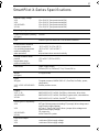
SmartPilot X-Series Specifications.....................................................................37
Glossary ....................................................................................................................... 39
Index..............................................................................................................................41
81307_1.book Page ii Wednesday, December 19, 2007 11:17 AM

Preface iii
Contents
Preface
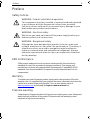
Safety notices
EMC Conformance
All Raymarine equipment and accessories are designed to the best industry
standards for use in the recreational marine environment. Their design and
manufacture conforms to the appropriate Electromagnetic Compatibility (EMC)
standards, but correct installation is required to ensure that performance is not
compromised.
Warranty
To register your new Raymarine product, please take a few minutes to fill out the
warranty card. It is important that you complete the owner information and return the
card to us to receive full warranty benefits. You can also register online at
www.raymarine.com
by following the
Login or create an account
link.
Pressure washing
Subjecting any Raymarine product to high pressure washing may cause subsequent
water intrusion and failure of the product. Raymarine will not warranty product
subjected to high pressure washing.
WARNING: Product installation & operation
This equipment must be installed, commissioned and operated
in accordance with the Raymarine instructions provided.
Failure to do so could result in personal injury, damage to your
boat and/or poor product performance.
WARNING: Electrical safety
Make sure you have switched off the power supply before you
make any electrical connections.
WARNING: Navigational safety
Although we have designed this product to be accurate and
reliable, many factors can affect its performance. Therefore, it
should serve only as an aid to navigation and should never
replace commonsense and navigational judgement. Always
maintain a permanent watch so you can respond to situations
as they develop.
81307_1.book Page iii Wednesday, December 19, 2007 11:17 AM

iv SmartPilot X-Series Commissioning & Setup Guide
Product documents
This document is part of a series of books associated with the Raymarine
SmartPilot X (SPX) series of autopilot systems.
These documents can be downloaded from www.raymarine.com/handbooks
To the best of our knowledge, the information in the product documents was correct
when they went to press. However, Raymarine cannot accept liability for any
inaccuracies or omissions in product documents.
In addition, our policy of continuous product improvement may change specifications
without notice. Therefore, Raymarine cannot accept liability for any differences
between the product and the accompanying documents.
Important
This book does not apply to the SPX-5 series of autopilots. These have their own
Installation & Setup Guides (Part Numbers 87075, 87075 and 87076).
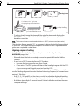
Product disposal
Waste Electrical and Electronic (WEEE) Directive
The European WEEE Directive requires that waste electrical and electronic
equipment is recycled.
Products carrying the crossed out wheeled bin symbol (illustrated above)
must not be disposed of in general waste or landfill, but in accordance with local
regulations for such products.
Although the WEEE Directive does not apply to all Raymarine products, we support
its policy and ask you to be aware of the correct method for disposing of such
products.
Please contact your local dealer, national distributor or Raymarine Technical Services
for information on product disposal.
Title Part number
ST6002 SmartPilot Controller Operating Guide 81269
ST7002 SmartPilot Controller Operating Guide 81270
ST8002 SmartPilot Controller Operating Guide 81271
ST70 AutoPilot Controller - SPX System Commissioning 81287
SmartPilot Surface Mount Controller Installation Guide 87058
SPX SmartPilot System Installation Guide, SPX 10, SPX 30,
SPX Solenoid
87072
Fluxgate compass installation sheet 87011
Warranty Booklet 80017
81307_1.book Page iv Wednesday, December 19, 2007 11:17 AM

1
Chapter 1: Procedures
WARNING: Calibration requirement
All autopilot systems must be commissioned before use.
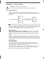
1.1 Applicability
This chapter describes the commissioning and initial setup procedures for the
following combinations of Raymarine SmartPilot X (SPX) autopilot systems and Pilot
Controllers:
Note:
This book does NOT apply to SPX-5 systems or to systems using ST70 Pilot Controllers.
If your SPX system is controlled with an ST70 Pilot Controller, the information in this
book does not apply. Instead use the procedures in
ST70 AutoPilot Controller - SPX
System Commissioning
(part no. 81287), to commission the system.
Requirement
The commissioning procedures are mandatory and must be carried out after
installation, before an SPX system is used to steer the boat. The commissioning
procedures comprises a series of dockside preparatory procedures and a short
seatrial.
Additional setup procedures enable you to fine tune your SPX system for optimum
performance with your boat. These procedures are not mandatory and you may find
that you do not need to use them if the SPX system operates to your satisfaction after
commissioning.
SPX-CAN systems
An SPX-CAN system connected to a Volvo Penta IPS system, must be auto-
configured in accordance with the procedure in the SPX-CAN Installation Guide,
before attempting to commission the SPX-CAN system.
If you experience any problems when commissioning and setting up an SPX-CAN
system connected to a Volvo Penta IPS system, repeat the auto configuration
procedure, then start the commissioning procedure again.
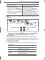
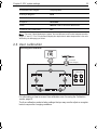
A
ny of these systems
SPX-10
SPX-SOL
SPX-CAN
SPX-30
or
or
or
ST6002
ST7002
ST8002
or
or
controlled by any of
these controllers
81307_1.book Page 1 Wednesday, December 19, 2007 11:17 AM

2 SmartPilot X-Series Commissioning & Setup Guide
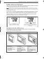
Rudder reference information
In SPX-30, SPX-SOL & SPX-CAN systems, the rudder position is shown by a rudder
reference bar and indicator on the Pilot Controller display.
Note:
The SPX-30 and SPX-SOL systems obtain rudder reference information from a rudder
reference transducer. The SPX-CAN system rudder reference information is provided by the as-
sociated Volvo IPS system.
The basic SPX-10 system is supplied without a rudder reference transducer, so in the
basic system, the Pilot Controller display does not show a rudder reference bar or
indicator. However, the SPX-10 system is compatible with the Raymarine rudder
reference transducer, and this can be fitted as an option.
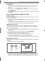
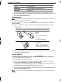
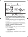
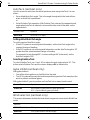
SeaTalk Controller differences
Minor differences in the control functions of the ST6002, ST7002 and ST8002
SeaTalk Pilot Controllers are as follows:
ST6002 Controller ST7002 Controller ST8002 Controller
• standby & auto
function keys
• +1, -1, +10 & -10 course
change keys
• disp & track extended
function keys
• standby & auto
function keys
• +1, -1, +10 & -10 course
change keys
• resp, track, mode, res’m,
disp, up & down extended
function keys
• standby & auto
function keys
• Rotary course change con-
trol
• resp, track, mode, res’m,
disp, up & down extended
function keys
Display in systems with rudder reference
information
D10779-1
Display in basic SPX-10 system
D6400-1
D6401-1
D6402-1
81307_1.book Page 2 Wednesday, December 19, 2007 11:17 AM

Chapter 1: Procedures 3
1.2 Commissioning procedures
Dockside preparation
The dockside preparation procedures comprise:
1. Switching on.
2. Checking SeaTalk and NMEA 0183 connections.
3. Checking rudder bar and steering operating sense, for either:
• SPX-10, SPX-30 & SPX-SOL systems
or
• SPX-CAN system
4. Dealer calibration settings. These are:
• Setting vessel type and drive type.
• Aligning rudder bar (if rudder reference transducer fitted).
• Setting rudder limits (if rudder reference transducer fitted).
WARNING: Ensure safe control
For safe control of your boat, you MUST complete the dockside
preparation before starting the initial seatrial.
If you are commissioning an SPX-CAN system connected to a Volvo Penta IPS
system, ensure the IPS system has been auto-configured in accordance with the
procedure in the SPX-CAN Installation Guide, before attempting to carry out the
commissioning procedure.
With the boat safely tied up, complete the following dockside preparation.
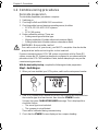
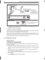
Step 1 - Switching on
1. When you have installed your SPX system, switch on the main power breaker.
2. If the SPX controller and computer are active, the controller will beep and show
the controller type for a few seconds, then show the
STANDBY
screen.
You may also see a
CALIBRATE REQUIRED
message. This is displayed for a
short time if either:
• The vessel type is not selected.
• The compass is not calibrated.
These will be calibrated during commissioning.
3. Check that the
STANDBY
screen displays a live compass heading.
D10524-1
TRUE
81307_1.book Page 3 Wednesday, December 19, 2007 11:17 AM

4 SmartPilot X-Series Commissioning & Setup Guide
Troubleshooting
• If the Pilot Controller does not beep or the display is blank, switch off the power,
then check the fuse/circuit breaker and the SeaTalk fuse in the SPX Course
Computer.
• If the display shows the
SEATALK FAIL
or
NO PILOT
alarm message, check the
SeaTalk connections.
• If the
STANDBY
screen does not display a live compass heading, check the sensor
connections.
Step 2 - Checking SeaTalk and NMEA connections
SeaTalk connections
If you have connected the Pilot Controller to other SeaTalk instruments or controllers,
check the links as follows:
1. Select display lighting level 3 (
LAMP 3)
on one of the other SeaTalk instruments or
controllers.
2. Check that the Pilot Controller display lights are on. If the lights are not on, check
the SeaTalk cabling between the Pilot Controller and the other units.
NMEA navigator connections
If the SPX system is connected to an NMEA navigator, ensure this is providing
waypoint information, then check the links by displaying the default navigation data
pages on the Pilot Controller:
1. Press
disp
to display the first data page (
XTE
), and check that this page shows the
expected data.
2. Press
disp
again to check each successive data page (
BTW
,
DTW
etc).
If the display shows dashes instead of data values, ensure:
• The navigator is switched on and transmitting an active waypoint.
• The navigator is configured to transmit the required data format.
• There is not a cabling error. Check for open circuit, short circuit or reversed wires.
Wind instrument connections
If the SmartPilot is connected to a SeaTalk or NMEA wind instrument, check the links
as follows:
1. Simultaneously press
standby
and
auto
.
2. Check that the Pilot Controller displays the Wind Vane mode screen, with the
locked wind angle and locked heading. If WIND mode is not displayed, the SPX
system is not receiving wind data. Check the wind instrument and connections.
MAG
D10532-1
+
81307_1.book Page 4 Wednesday, December 19, 2007 11:17 AM

Chapter 1: Procedures 5
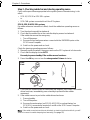
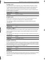
Step 3 - Checking rudder bar and steering operating sense
Carry out the procedures appropriate to the system you are commissioning, i.e for
either:
• SPX-10, SPX-30 or SPX-SOL system
or
• SPX-CAN system connected to a Volvo IPS system.
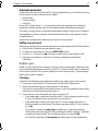
SPX-10, SPX-30 & SPX-SOL systems
If a rudder reference transducer is fitted, check the rudder bar operating sense as
follows:
1. Turn the wheel manually to starboard.
2. Check that the rudder bar on the controller display moves to starboard.
If the rudder bar moves the wrong way:
i. Turn off the power.
ii. Reverse the red and green wires connected to the
RUDDER
inputs on the
SPX Course Computer.
iii. Switch on the power and re-check.
Check the steering operating sense as follows:
1. Manually center the wheel, then press
auto
so the SPX system is in Auto mode.
2. Check that the display shows
AUTO
.
Be ready to press standby if the rudder moves hardover.
3. Press the +10 key once or turn the rotary control ½ turn clockwise.
4. Check that the rudder moves to starboard a few degrees, then stops. If the rudder
drives hard over, immediately press
standby
to prevent further rudder
movement.
5. If the rudder moves to port or the rudder drives hard over:
i. Press
standby.
ii. Turn off the power.
iii. Reverse the motor wires (on SPX-10 & SPX-30) or solenoid wires (on
SPX-SOL), connected to terminals A and B on the SPX Course Computer.
iv. Switch on the power and re-check.
Note:
If the rudder overshoots and has to drive back or starts to hunt back and forth, you will
need to increase the rudder damping level manually (See
page 30
).
D10745-1
ST6002
ST7002
ST8002
½ turn
81307_1.book Page 5 Wednesday, December 19, 2007 11:17 AM

6 SmartPilot X-Series Commissioning & Setup Guide
SPX-CAN system connected to Volvo IPS system
Before making any adjustments to an SPX-CAN system, ensure the auto-
configuration procedure (see the
SPX_CAN System Installation Guide
) has been
carried out.
Check the rudder bar operating sense as follows:
1. Power up the SPX-CAN system
2. Start the boat engine.
3. Turn the wheel manually.
4. Check that the rudder bar on the controller display follows the helm movement.
If the rudder bar does not follow the helm, ensure the SPX-CAN system wiring is
correct.
Check the steering operating sense as follows:
1. Manually center the wheel.
2. With the boat engine running, press
auto
.
Be ready to press standby if the rudder moves hard over.
3. Press the +10 key once or turn the rotary control ½ turn clockwise.
4. Check that the rudder moves to starboard a few degrees, then stops. If the rudder
drives hardover, immediately press
standby
to prevent further rudder movement.
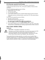
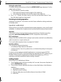
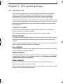
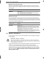
Step 4 - Dealer calibration settings
Introduction
To proceed with the dockside preparation, you need to carry out certain Dealer
calibration setup functions. The exact requirement and consequently the calibration
screens displayed, depend on which SPX system you are calibrating and whether a
rudder reference transducer is fitted, as summarized in the following diagram.
WARNING: Use Dealer calibration correctly
Improper use of Dealer calibration can seriously impair the SPX
system performance and therefore adversely affect the
steering capability. Do not change Dealer calibration settings
other than as described in the product documentation.
81307_1.book Page 6 Wednesday, December 19, 2007 11:17 AM

Chapter 1: Procedures 7
Entering Dealer calibration
Enter Dealer calibration as follows:
1. Ensure the SPX system is in Standby mode.
2. Referring to the following table, use the appropriate procedure to enter Dealer
calibration mode.
SPX-10 SPX-30 SPX-SOL SPX-CAN
Rudder ref
fitted
DEALER CALIBRATION
Enter
DEALER CALIBRATION
Leave
CAL
screen
CAL
screen
CAL
screen
Yes
No
CAL
screen
Setup map
D10787-1
81307_1.book Page 7 Wednesday, December 19, 2007 11:17 AM

8 SmartPilot X-Series Commissioning & Setup Guide
Note:
For more information on settings and calibration modes, refer to
Chapter 2: SPX sys-
tem settings
.
3. In Dealer calibration, access the vessel type screen, using
disp
if necessary. The
vessel type screen shows either
VESSEL
or one of the vessel types (
DISPLACE
,
SEMI DISPLACE
,
PLANING
,
STERN DRV
,
WORK BOAT
or
SAIL BOAT
).
Setting vessel type
The vessel type setting automatically determines appropriate default values for
various other calibration settings. Some of these settings are checked later in this
procedure and others should not require any adjustment. The default values for each
vessel type are listed on
page 35
.
Set the vessel type as follows:
1. Use
-1
or
+1,
or the
rotary control
to set the appropriate vessel type, as in the
following table.
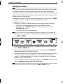
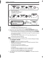
ST6002 Controllers ST7002 and ST8002 Controllers
1 Press and hold
standby
for two seconds
to enter the Calibration mode
2 When the screen shows
DISPLAY CAL
,
press
disp
until you see the
DEALER CAL
screen
3 Press
auto
: the display will change to
CAL
4 Simultaneously press -1 and +1 to enter
Dealer calibration mode
1 Press and hold
standby
for two seconds to
enter the Calibration mode
2 When the screen shows
DISPLAY CAL
,
press
disp
or the up and down arrows, until
you see the
DEALER CAL
screen
3Press
auto
: the display will change to
CAL
4 Simultaneously press -1 and +1 (on the
ST7002) or the up and down arrows (on the
ST8002), to enter Dealer calibration mode
Type Description
DISPLACE
Power-driven boats which do not plane
(Typically below 15 kts top speed)
SEMI DISPLACE
Faster power-driven boats which do not plane
(Typically 15-20 kts top speed)
PLANING
Planing boats with inboard engine(s) and shaft drives
(NOT boats with outdrives)
STERN DRV
Boats with outdrives or outboard engines
At the CAL screen, press + together to enter DEALER CAL
2 sec
x3
-1 +1
or
D10746-1
(ST8002 only)
+
81307_1.book Page 8 Wednesday, December 19, 2007 11:17 AM

Chapter 1: Procedures 9
2. Press
disp
to confirm your selection and move to the next calibration screen. See
the
Setup map
diagram above.
Setting drive type
Note:
On SPX-SOL and SPX-CAN systems, the drive type is set automatically so the DRIVE
TYP calibration screen is not displayed.
On SPX-10 and SPX-30 systems the
DRIVE TYP
screen is displayed. Set the drive
type as follows:
1. Use
-1
or
+1,
or the
rotary control
to set the appropriate drive type, as in the
following table.
2. Press
disp
to confirm your selection and move to the next calibration screen. See
the
Setup map
diagram above.
Aligning rudder bar
If a rudder reference transducer is fitted, the
ALIGN RUDDER
screen is displayed.
Align the rudder indicator as follows:
1. Use the wheel to center the rudder.
2. Use
-1
or
+1,
or the
rotary control
to adjust the rudder indicator so it is at the
center of the rudder bar on the Pilot Controller display.
The maximum adjustment available is ±9°. If the offset is beyond these limits, you
will need to physically adjust the alignment of the sensor.
3. Press
disp
to confirm the rudder bar alignment and move to the next screen
.
See
the
Setup map
diagram above.
Note:
You can also zero the rudder bar with the boat underway during the initial seatrial (see
page 13
).
WORK BOAT
Commercial tugs, fishing vessels, etc
SAIL BOAT
Sailing boat
Drive Drive Type Setting
Drive Type 3
Linear
Rotary
Typically found on yachts
I/O (stern)
Found on Powerboats
Drive Type 4
Hydraulic reversing pump
Used on yachts and power-
boats with hydraulic steering
Type Description
D
1
0
7
9
1
-
1
D10792-1
81307_1.book Page 9 Wednesday, December 19, 2007 11:17 AM

10 SmartPilot X-Series Commissioning & Setup Guide
Setting the rudder limits
If a rudder reference transducer is fitted, the
RUDDER LIMIT
page displayed. Set the
rudder limits as follows:
1. Turn the wheel to move the rudder:
i. To the port end stop and note the angle on the rudder bar.
ii. To the starboard end stop and note the angle on the rudder bar.
2. Use
-1, +1, -10
and
+10
or the
rotary control
to set the rudder limit to 5° less
than the lowest angle you have noted.
Finishing dockside preparation
Hold down
standby
for 2 seconds to save the Dealer calibration settings and return
to Standby mode.
Seatrial calibration
When you have successfully completed the dockside preparation, carry out a Seatrial
calibration, to calibrate the compass and set up the autopilot steering characteristics.
Important
If you need to return to manual steering at any time during a Seatrial or any other
procedure, press the standby button. NEVER compromise vessel safety.
EMC conformance
Always check the installation before going to sea to make sure that it is not affected by
radio transmissions, engine starting etc.
This is particularly important when carrying out a Seatrial.
Seatrial conditions
The seatrial must be carried out only:
• In conditions of light wind and calm water.
• In waters that are clear of any obstructions, so the boat has plenty of clear space
to maneuver.
In order to achieve optimum autopilot performance, course over ground (COG),
speed over ground (SOG) or boat speed data are required at the SPX system (e.g. on
SeaTalk). Ensure that the equipment providing this information (e.g. GPS), is
switched on and fully operational, before starting a Seatrial.
Getting started
Start the SeaTrial calibration as follows:
1. From Standby mode, hold down
standby
for 2 seconds, then press
disp
twice to
see the
SEATRIAL CAL
screen.
2. Carry out the Seatrial calibration functions as described below, in the following
sequence:
i. Swinging the compass
ii. Aligning compass heading
iii. Aligning rudder bar (only if rudder reference transducer is fitted)
iv. AutoLearn
81307_1.book Page 10 Wednesday, December 19, 2007 11:17 AM

Chapter 1: Procedures 11
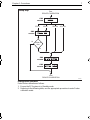
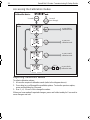
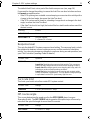
Swinging the compass
Note:
This section does not apply if you have connected an NMEA compass to your SPX sys-
tem. Refer to the handbook supplied with the NMEA compass for information about calibration.
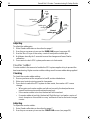
The magnetic deviation correction procedure (commonly called “swinging the
compass”) involves turning your boat in slow circles so the autopilot can automatically
determine the deviation and apply any correction required. This procedure reduces
deviation errors to a few degrees.
As magnetic deviation can cause significant compass errors on your boat, you MUST
complete the compass swing before any other seatrial procedure.
To swing the compass:
1. With the SPX system in Standby mode, enter Seatrial calibration as follows:
i. Hold down
standby
for two seconds to enter Calibration mode.
ii. When you see the
DISPLAY CAL
screen, press
disp
until you see the
SEATRIAL CAL
screen.
iii. Press
auto
to enter Seatrial calibration.
Note:
If you cannot access Seatrial calibration, disable the calibration lock. (see
page 28
).
2. Use
disp
as necessary, to move through the Seatrial Calibration items until you
see
SWING COMPASS.
3. When you are ready to start, press
+1
, or turn the
rotary control
clockwise, to
select
SWING COMPASS ON
.
4. Press
auto
to start the compass swing. The controller will display
TURN BOAT
indicating the start of the calibration process.
5. Ensuring you keep the boat’s speed below 5 knots, start slowly turning the boat in
circles at a constant speed, maintaining a turn rate of approximately 3° per
second, i.e. taking approximately 2 minutes to complete one turn. Complete at
least two circles, in this manner.
If you turn the boat too quickly, the display will show a
TOO FAST
message. If this
occurs, apply less helm to reduce the rate of turn.
Note:
If necessary, you can quit the correction process by pressing
standby
or
disp
. If you then
want to repeat the deviation correction, return to the
SWING COMPASS
screen.
2 sec
x2
D10541-1
81307_1.book Page 11 Wednesday, December 19, 2007 11:17 AM

12 SmartPilot X-Series Commissioning & Setup Guide
6. Continue slowly turning the boat until the controller beeps and displays the
DEVIATION
screen. This indicates that the SPX system has completed the
deviation correction.
Note:
This screen shows the maximum deviation over 360° (not as an east/west value).
If the deviation figure exceeds 15°, the compass is being affected by ferrous objects
on your boat. You should move the compass to a better location. Higher deviation
figures are acceptable on steel boats.
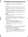
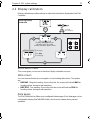
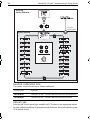
Aligning compass heading
Once the deviation is displayed, press
disp
to move to the Align Heading
(
ALIGN HDG
) page, then:
1. Manually steer the boat on a steady course at a speed sufficient to hold the
course.
2. If you have a GPS connected to your SPX system:
• Increase the boat speed to more than 3 knots.
•Press
auto
. The SPX system will then set the heading to agree with the COG
(course over ground) heading received from the GPS.
As many factors can cause a difference between heading and COG, you must fine-
tune the heading alignment to match the boat’s steering compass (or a known transit
bearing). To do this:
1. Use
-1,
+1
,
-10
and
+10
or the
rotary control
to adjust the displayed heading
until it matches the boat’s steering compass (or a known transit bearing).
2. Hold down
standby
for 2 seconds to exit Seatrial calibration and save the new
compass settings.
D10761-1
Slowly turn boat in circles:
• at a turn rate of 3˚ per second
• keeping boat speed below 5 knots
Minimum of
2 circles
Keep turning the boat until
you see the DEVIATION screen
Start
turning boat
to Align Heading
81307_1.book Page 12 Wednesday, December 19, 2007 11:17 AM

Chapter 1: Procedures 13
Although compass calibration removes most of the alignment error, small errors (a
few degrees) may remain. Once you have completed the initial compass calibration,
you can make further adjustments to the alignment without having to swing the
compass again.
Check the heading reading against a number of known headings, plot a deviation
curve, and determine the heading alignment value that will give the lowest average
alignment error. You can then enter this value on the Heading Alignment screen, as
described above.
If the average heading error is more than 5°, check there are no items close to the
compass that could cause an unwanted magnetic influence. You should also consider
moving the fluxgate compass and performing the compass deviation correction
procedure again, circling more slowly and in more favorable conditions.
Aligning rudder bar
If the rudder reference transducer is fitted, use this procedure to align the rudder bar
on the Pilot Controller display:
1. Access the
ALIGN RUDDER
screen in Seatrial calibration:
i. From Standby mode, hold down
standby
for 2 seconds, then press
disp
twice
to see the
SEATRIAL CAL
screen.
ii. Press
auto
to enter Seatrial calibration, then press
disp
tree times to see the
ALIGN RUDDER
screen.
2. Steer straight ahead then use
-1,
+1
,
-10
and
+10
or the
rotary control
to set the
displayed rudder bar to zero.
2 sec
D10777-1
Align the autopilot heading
a
b
Save changes
To:
• save deviation correction
• save heading alignment
• return to STANDBY mode
Autopilot heading
Steering compass
=
Known
heading
or
or
Adjust the autopilot heading so it shows the same value as the boat's steering compass
Coarse adjustment: If COG is available from GPS, press to set autopilot heading to
COG value, then fine tune manually (see below).
Fine adjustment: If COG is not available (or after setting heading to COG),
align autopilot heading manually:
ST6002 & ST7002
ST8002
81307_1.book Page 13 Wednesday, December 19, 2007 11:17 AM

14 SmartPilot X-Series Commissioning & Setup Guide
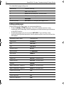
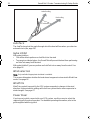
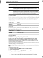
AutoLearn
The next stage of the Seatrial is to carry out an AutoLearn routine. This is a self-
learning calibration feature that automatically adjusts rudder gain, counter rudder and
AutoTrim for optimum performance on your boat.
If you need to return to manual steering at any time during an AutoLearn routine or any
other procedure, press the
standby
button. NEVER compromise vessel safety.
Ensure you have sufficient sea room to complete the AutoLearn, then carry out the
AutoLearn as follows:
1. If you are not already in Seatrial calibration:
i. From Standby mode, hold down
standby
for 2 seconds, then press
disp
twice
to see the
SEATRIAL CAL
screen.
ii. Press
auto
to enter Seatrial calibration
iii. Press
disp
four times to see the
AUTOLEARN
screen.
2. In Seatrial calibration, press
disp
as necessary, until the
AUTOLEARN
screen is
displayed.
3. With the
AUTOLEARN
screen displayed, prepare to start the AutoLearn:
• power boats: steer straight ahead (rudder centered). For non-planing boats,
set a comfortable cruising speed. For planing boats set the speed so the boat
is just planing.
• sail boats: with the sails down, steer straight ahead (rudder centered) and
motor the boat at typical cruising speed.
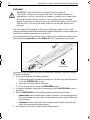
4. If conditions are not calm, head into the wind and waves.
WARNING: Ensure there is enough clear sea space
The AutoLearn process takes the boat through a number of
maneuvers, which can result in sudden, sharp turns, especially
when the AutoLearn function is run on more maneuverable
boats. Therefore, ensure there is a significant amount of CLEAR
SEA SPACE in front of the boat, before starting an AutoLearn
process.
At least 0.25 nm (500 m) of clear sea space
At least 0.04 nm (100 m)
of clear sea space
D5495-2
1 minute
(approximately)
Wind
81307_1.book Page 14 Wednesday, December 19, 2007 11:17 AM
Page is loading ...
Page is loading ...
Page is loading ...
Page is loading ...
Page is loading ...
Page is loading ...
Page is loading ...
Page is loading ...
Page is loading ...
Page is loading ...
Page is loading ...
Page is loading ...
Page is loading ...
Page is loading ...
Page is loading ...
Page is loading ...
Page is loading ...
Page is loading ...
Page is loading ...
Page is loading ...
Page is loading ...
Page is loading ...
Page is loading ...
Page is loading ...
Page is loading ...
Page is loading ...
Page is loading ...
Page is loading ...
-
 1
1
-
 2
2
-
 3
3
-
 4
4
-
 5
5
-
 6
6
-
 7
7
-
 8
8
-
 9
9
-
 10
10
-
 11
11
-
 12
12
-
 13
13
-
 14
14
-
 15
15
-
 16
16
-
 17
17
-
 18
18
-
 19
19
-
 20
20
-
 21
21
-
 22
22
-
 23
23
-
 24
24
-
 25
25
-
 26
26
-
 27
27
-
 28
28
-
 29
29
-
 30
30
-
 31
31
-
 32
32
-
 33
33
-
 34
34
-
 35
35
-
 36
36
-
 37
37
-
 38
38
-
 39
39
-
 40
40
-
 41
41
-
 42
42
-
 43
43
-
 44
44
-
 45
45
-
 46
46
-
 47
47
-
 48
48


Raymarine SPX-SOL Setup Manual
- Type
- Setup Manual
- This manual is also suitable for
Ask a question and I''ll find the answer in the document
Finding information in a document is now easier with AI
Related papers
-
Raymarine SmartPilot ST6002 Quick Reference Manual
-
Raymarine SmartPilot X-5R Installation guide
-
-
-
-
-
-
-
-
Other documents
-
Seiwa Autopilot SW AP01 Owner's manual
-
 Seiwa Autopilot SW AP03/(NEW) AP13 User manual
-
Garmin GHC 20 Control Unit Owner's manual
-
Furuno FI507 User guide
-
Yanmar Joystic Control System JC10 Operating instructions
-
Simrad NAC-2 and NAC-3 Installation guide
-
 Raytheon Electronics ST6000 Plus Specification
-
Raytheon ST6000 Plus Specification
-
NORTHSTAR Pilot System NS3300 User manual
-
Garmin TR-1 Gold Marine Autopilot User manual

