Page is loading ...

Electrical Parameters:
Figure 1
Figure 3
35, MRL-61350NW
155
3
Figure 4
5", 6" LED Downlight Installation Instructions
ese instructions Type luminaires.
WARNING / ATTENTION
CAUTIONS
1. For your safety read and understand instructions completely before starting installation.
2. Before attempting Installation, check your local electric code, as it sets wiring standards for
your
locality.
NOTES
1. . Supply conductors (power wires) connecting to the fixture must be rated 90°C.
If uncertain consult an electrician.
2.
3.
qualified electrician.
4.
where the input rating of
the retrofit kit does not exceed the input rating of the luminaire
5.
other
6. This lamp is not intended for use with emergency exit fixtures or emergency lights.
1. If luminaire (fixture) is to be switched from a wall switch, make sure black power supply wire
is connected to the switch. DO NOT connect the white supply wire to the switch.
2. Make sure no bare wires are exposed outside the wire nut connectors.
3.
during kit installation.
4. THIS RETROFIT KIT IS ACCEPTED AS A COMPONENT OF A LUMINAIRE WHERE THE SUITABILITY
OF THE COMBINATION SHALL BE DETERMINED BY AUTHORITIES HAVING JURISDICTION.
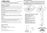
Housing Dimensions
Inner 6.25
5. There must be at least 5" of height from the
surface of the can housing to the surface of the E26
socket inside. These dimensions must be met to ensure
the downlight will sit flush with the ceiling.
Installation Into Recessed Housing:
STEP1: . Remove
the existing diffuser, bulb and trim as applicable.
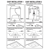
STEP2: Torsion springs are pre-installed for 6" housing
compatibility. For use in 5" housing move both springs to
the 5" position as shown on the reverse side of these
instructions.
STEP3: Screw E26 socket adapter into socket in
housing. (Figure 1)
STEP4: Plug the connector of the retrofit kit
into the connector of the socket adapter
assembly. (Figure 2)
STEP5: Squeeze the torsion springs together and install
into torsion spring brackets inside the housing as shown.
(Figure 3)
STEP6: Tuck all wires into the housing and carefully
push the LED trim until its outer edge is flush against the
ceiling surface. (Figure 4)
www.maxximastyle.com
Luminous Intensity Distribution Diagram
Five Year Warranty:
Maxxima extends a 5 year limited warranty to the original purchase that the products listed are free from defects in material and/or
workmanship only. Maxxima will replace any warranteed product to the original consumer/purchaser if the product fails because of defects
due to workmanship and/or materials within the limited warranty period.
Limited warranty is not transferable and applies to the original
installation of the Maxxima product. This offer does not constitute in any way a product guarantee and Maxxima does not hereby
assume any obilgation whatsoever beyond sending a free replacement product.
18
S
O
A
L
W
I
D
G
Figure 2

Torsion Spring Relocation
NOTE: Torsion springs are pre-installed for 6" housing compatibility. For use in 5" housing move both
springs to the 5"position. To do this, loosen each side of Torsion Spring holder bracket screw and slide
bracket to where screw is next to the 5 for 5" housing and where it is next to the 6 for 6" housings. Then
tighten screw to secure Torsion Spring bracket and repeat for other side.
Torsion Springs in 6" Position
Torsion Springs in
5" Position
Screw secured next to 6 on bracket.
Screw secured next to 5 on bracket.
7.5"
2.3"
7.8"
Product Dimensions
2.7"
/