
Invacare
®
English
Service Manual

2 INVACARE
®
XLT Service Manual

3
INVACARE
®
XLT Service Manual
9
3
13
12
1
4
11
5
8
7
10
2
6
14
Product description ................................................ 4
XLT Models .............................................................. 5
NB! ............................................................................. 6
Lifting the wheelchair ............................................. 6
Intended use ............................................................. 7
Upholstery and frame colours ............................. 8
Equipment and accessories ................................... 8
Technical data .......................................................... 9
Adjustments:
Legrests ................................................................... 10
Calf pads/Footplates ............................................. 11
Seat ........................................................................... 13
Backrest ................................................................... 14
Armrests/Mudguards ............................................ 17
Brakes ...................................................................... 18
Rear wheels ........................................................... 19
Castor wheels ........................................................ 20
Wheelchair heights ............................................... 21
Contents
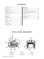
1. Frame (chassis)
2. Backrest
3. Push handles
4. Seat
5. Rear wheel
Parts of the wheelchair
Accessories:
Anti-tip devices ...................................................... 29
Trunk support........................................................ 31
One-arm drive ....................................................... 32
Assistant manoeuvred drumbrakes .................. 33
Amputee legrest/External push handles .......... 34
Foldable push handles .......................................... 35
Pelvic belt ................................................................ 35
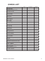
Washing and Disinfection ................................... 36
Reconditioning ....................................................... 37
Tool List .................................................................. 38
Check List ............................................................... 39
6. Hand rims
7. Brakes
8. Castors
9. Anti tip device
10. Armrests
11. Jaw
12. Legrests
13. Footrest
14. Footbow

4 INVACARE
®
XLT Service Manual
Invacare® XLT is a wheelchair with many adjustment options and
accessories. To ensure that you benefit as much as possible from your
Invacare® XLT, and in order to do its options justice, the chair must be
tested and adjusted by competent personnel. We hope that you have also
received instructions for using your Invacare® XLT in everyday life.
The Invacare® XLT frame, footbow and backrest are manufactured
from high quality titanium. For the Swing version the legrest hangers
are made from aluminium. The cover for the seat cushion is made of
Jemima and the backrest cover is made of nylon.
This manual includes a description of the parts of the chair, simple
adjustment options, how to use the Invacare® XLT safely and how
to transport it. The manual must be read thoroughly before the chair
is used. Also included in this manual is a description of how the most
common accessories are fitted and also some slightly more advanced
settings.
As the Invacare® XLT has many different components and accessories,
the appearance of the accessories you have for your chair may differ
from those shown.
Product description
Invacare
®
XLT

5
INVACARE
®
XLT Service Manual
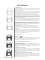
XLT Power U-front
XLT Power V-front
XLT Nordic
XLT Active
XLT Dynamic
XLT Swing
XLT Models
Until January 2004:
XLT is made of titanium which is very light and strong. This makes it a light, stable
and durable wheelchair. XLT fits in almost everywhere thanks to its comfort,
ergonomics and performance.
XLT is designed for experienced, active users, who understand how important it is
with good propelling characteristics. The very stable chassis and the excellent wheel
balance provide good propelling characteristics on almost every surface.
XLT is designed for easy handeling and transport, wherever you want to travel.
XLT is well balanced for an one-arm lift into a car. It takes up so little space that
it easily can be lifted in front of you into the passanger seat of a car. Titanium is
also extra strong and durable which gives it a long life. Quick release wheels and
foldable back, is of course standard.
XLT is a solid frame wheelchair with driving wheel plates and castor attachments of
aluminium. This provides a light weight and stable wheelchair. The black vinyl seat
is easy to clean. The back rest is made of black plastic-coated fabric/black Strix.
XLT Power U-front has a front that helps keep together the lower parts of
the legs and the feet. The standard delivery includes a foot bow. With 120 mm
castors the seat angles 4°, 8°, and 12° can be obtained, dependent on the row of
mounting holes used for the rear wheel.
XLT Power V-front has a front that helps keep together the feet. The
standard delivery includes a foot bow. With 120 mm castors the seat angles 4°,
8°, and 12° can be obtained, dependent on the row of mounting holes used for
the rear wheel.
XLT Box has a front offering more space for the lower parts of the legs and the
feet. The standard delivery may include a foot bow or collapsible footrests. With
120 mm castors the seat angles 3° or 8° can be obtained, dependent on the row
ofof mounting holes used for the rear wheel.
Frame, footbow and backrest are manufactured from high quality titanium. For the
Swing version the legrest hangers are made from aluminium. The cover for the seat
cushion is made of Jemima and the backrest cover is made of nylon.
The new XLT is available in the models:
XLT Active (75° knee angle)
is designed to hold your feet and lower parts of your leg steady. The footbow is
delivered as standard. Seat angles 0-14° can be obtained, depending on the size of
castors and rear wheels and the row of mounting holes used for the castors and
rear wheels.
XLT Dynamic (90° knee angle)
is desgned to hold your feet steady. The wheelchair is very compact and the total
length is low. The footbow is delived as standard. Seat angles 0-14° can be obtained,
depending on the size of castors and rear wheels and the row of mounting holes
used for the castors and rear wheels.
XLT Swing (80°, 90° and angle adjustable legrests)
is desgned with a front offering more space for the feet and lower parts of the
legs. The standard delivery includes collapsible footrests. Seat angles 0-14° can be
obtained, depending on the size of castors and rear wheels and the row of mounting
holes used for the castors and rear wheels.
Invacare
From spring 2008:

6 INVACARE
®
XLT Service Manual
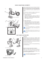
On this page a number of points affecting your personal safety are
shown. Please Read it carefully!
Invacare
®
is only responsible for product changes carried out by per-
sonnel who we authorise. We reserve the right to make any changes
to equipment and specifications without prior notice.
Failure to comply with instructions given may result in personal injury
and/or product damage.
• Check each of the following before using the wheelchair:
- that all parts are attached securely to the frame
- that all wheels and knobs are properly tightened
- that all brakes and anti-tip devices function correctly
• Never lift the wheelchair by the detachable armrests, footrests,
backrest stay or by the adjustable push handles.
• Always apply the brake before getting into or out of the chair.
• Never stand on the footplates when getting into or out of the chair,
because of the risk of tipping.
• Changing the seat angle always gives an increased risk of tipping
over.
• The hand rims may become hot due to friction, and this may cause
injury to your hands.
• Use extensively the anti-tip device
• Remember that the effectiveness of the carer-operated brake
is reduced in wet and slippery conditions, as well as when on a
slope.
• Be careful to ensure that the drive wheels are securely attached.
• Drive wheels are not to be detached while the user is sitting in the
chair.
• The more the backrest cover’s Velcro straps are slackened the
greater the risk of tipping the wheelchair becomes.
• Surfaces of the wheelchair like frame parts or upholstery can with
long time exposure to sun reach temperatures over 41 °C.
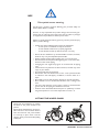
This symbol means warning.
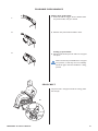
NB!
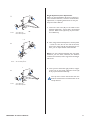
Always lift the wheelchair by grabbin
the frame at the points shown in the
picture.
Never lift the wheelchair by the remov-
able armrests or the footrests. Ensure
that the backrest and push handles
are securely in place. Also read the
chapter Safety instructions/Propelling
techniques.
LIFTING THE WHEELCHAIR

7
INVACARE
®
XLT Service Manual
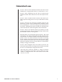
Intended use
• Invacare® XLT is a manual wheelchair aimed for those who use the
wheelchair for a longer period of time, i.e. several hours in a row.
• Invacare® XLT is designed for the user who can manoeuvre the
wheelchair him/her-self, as well as for the user who requires assist-
ance.
• Invacare® XLT is versatile and has accessories that makes it pos-
sible to adjust the sitting posture so it stays comfortable for several
hours.
• Invacare® XLT have many adjustment possibilities. With the right
adjustments, carried out by a professional the wheelchair can be
set up specifically for a user and according to the requirements of
his assistant. All adjustments that are possible, are described in the
Owners Manual that is delivered together with the wheelchair.
• Invacare® XLT can be used both indoors and outdoors on level
ground and paved areas. We recommend the larger wheels when
the wheelchair is used on uneven ground.
• Note that there is an increased risk that the Invacare® XLT could
tip backwards, when being wheeled uphill, especially when the incline
is more than 8°. Or if the rear wheels are mounted in their formost
position on the rear wheel attachment. The effect of mounting
the rear wheels in their foremost position is that the chair will be
easier to manoeuvre. However, there is the increased risk of tipping
backwards. Therefore the use of anti tip devices to achieve better
stability is strongly recommended.
• Invacare® XLT is designed to have a seat cushion on the seat. The
seat cushion improves the user's body posture and makes it possible
for him to sit comfortably for longer periods of time.
XLT Swing with a backrest, adjusted to a height of minimum •
48 cm, and a neckrest can be used as a seat in a vehicle. For other
models or configurations the user must transfer to the normal
seat in a car or bus.

8 INVACARE
®
XLT Service Manual
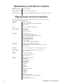
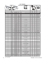
Equipment and accessories
Backrest cover Black Nylon TR33
Seat cushion cover Black Jermina TR18 (standard)
Frame colours Black, Grey, Blue and Red (Blasted titanium and Orange as special)
Invacare® XLT has a wide range of accessories and options. Some of the accessories
may not be available in all countries.
Backrest Tension adjustable
Angle adjustable, fixed or height adjustable
Narrow back
Seat Tension and depth adjustable seat
Seat cushions Standard 5 cm
Flo-Tech Lite
Flo-Tech Lite Visco
Legrests Footbow rigid**
Footbow rigid with footplate**
Footrest one piece, flipup, angle adjustable
Footrest, high mounted**
80° & 90° fixed legrest*
Angle adjustable legrest*
Fixed footplate*
Angle and depth adjustable footplate*
Armrests Flip-up armrest with long or short pad
Height adjustable armrest "Rio", with long or short pad
Hemi armrest
Castors 75 - 125 mm (Dynamic), 75 - 180 mm (Swing, Active)
Rear wheels 22", 24", 25", 26" pneumatic or puncture-proof
24", one-arm drive
Brake User-brake (3 types)
Carer-operated drumbrake
One-arm brake
Others Several types of handrims
Spoke guard
Anti-tip device
Trunk Support
Reflectors Kit
Table Tray
Pump
Cane holder
Tool kit
Various push handles
Pelvic belt
Mudguard
Sideguard
Step tube
Brake lever extension
Mounting brackets for E-Motion and E-Fix
* for XLT Swing only
** for XLT Active and Dynamic only
Upholstery and frame colours

9
INVACARE
®
XLT Service Manual
SW SD
ML
W
L
H
W
BASA
LL
AH
BH*
SH
TW
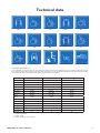
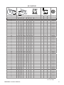
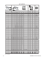
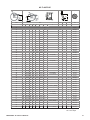
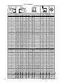
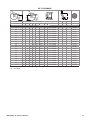
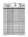
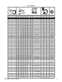
Technical data
* Fixed/Angle adjustable backrest
**Our wheelchairs comply with ISO norm 7176-19 and have been tested in a basic configuration. The use in other configurations has not
been tested. See section "Test report from dynamic safety restraint test", for test configuration. Wheelchair users should however transfer
to the vehicle seat and use the vehicle installed restraint system whenever it is feasible
Crash test**
* without seat cushion
** with 0° camber
*** without rearwheels and accessories
Active Dynamic Swing
SW (cm)
35,5/38/40,5/43/45,5/48 35,5/38/40,5/43/45,5/48 35,5/38/40,5/43/45,5/48/50,5
SD (cm)
36-40/41-45/46-50 36-40/41-45/46-50 36-40/41-45/46-50
SH (cm)*
40-52 40-52
39-52
BH (cm)* 20-35 / 30-49 20-35 / 30-49 20-35 / 30-49
AH (cm) 21-31 21-31 21-31
LL (cm)* 38-50,5 35,5-48,5 28-51
SA (°) 0°-14° 0°-14° 0°-14°
BA (°)
±10° ±10° ±10°
W (cm)** Seat width + 20 cm Seat width + 20 cm Seat width + 20 cm
H (cm) 61-105 61-105 61-105
L (cm) 83-103 73-88 82-123
W (kg) 9,8 9,8 11,3
ML (kg) 135 135 135
TW (kg)*** 6 6 6

10 INVACARE
®
XLT Service Manual
A
C
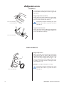
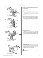
Adjustments
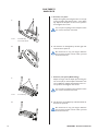
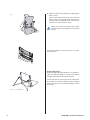
LEGRESTS
Height adjustment
Adjust the height of the footrests by loosening the
screw (A) one half turn with an Allen key. When
adjusting the height a clicking sound will occur. One
”click” is one step in height. Pull the legrest until
you have obtained the correct height and the screw
is caught by one of the recesses on the legrest tube.
Then retighten screw.
NOTE! Do not adjust the upper screw (C).
The distance between the lowest part of the
footrest and the floor or ground must be at
least 40 mm.
FIXED LEGRESTS
Tools: 5 mm Allen Key
It is important to adjust the footbow, footrests, leg-
rests, footplates and calf pads to obtain a good sea-
ting position
Height adjustment, footbow
Loosen the screws using an Allen key, remove them,
and adjust the footbow to the correct height. Retigh-
ten the screws and adjust the calf-strap.
The distance between the lowest part of the
footrest and the floor or ground must be at
least 40 mm.
High mounted footbow
Loosen the screws using an Allen key and adjust the
clamp and footbow to a suitable height. Retighten the
screws and adjust the calf-strap.
Tools: 4 mm Allen Key
10 mm fixed spanner
Tools: 5 mm Allen Key

11
INVACARE
®
XLT Service Manual
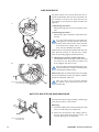
D
B
C
A
2.
B
C
1.
A
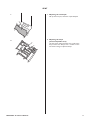
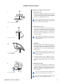
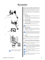
Depth- and angle adjustable footplates
Adjust the angle and the depth by loosening the
screw (A) at the footplate attachment with a
5 mm Allen key. Adjust the footplate to the correct
position and retighten the screw.
Do not place anything on the footplate when
the screws have been loosened.
Calf pads
The calf pads can be fitted in four different depth
positions. Swing the pad forwards. Unscrew screw
(B) using an Allen key. Remove the large nut (C) on
the reverse side and place it in the other attachment
hole. Move the calf pad to the new position and secure
it into place with the screw.
The height of the calf pads can easily be adjusted using
the handwheel (D).
CALF PADS/ FOOTPLATES
Tools: 5 mm Allen Key
Tools: 5 mm Allen Key
Angle adjustable legrests support the legs and reduce
pressure. The legrests can be used for bandaged legs,
but not for legs in plaster casts. The legrests must
always be fitted with calf pads, footplates and heel
straps.
It is important to adjust the height and angle of the
legrests to obtain a good seating position.
1. Height adjustment
Loosen screw (A) with an Allen key. Adjust the
legrest into a suitable height and the screw is
caught by one of the recesses on the legrest tube.
Then retighten the screw.
2. Angle adjustment
Pull the lever (B) with one hand while support-
ing the legrest with your other hand. When a
suitable angle is obtained, let go of the lever and
the legrest will look into one of seven preset
positions (C).
Do not place anything heavy, or let children
sit on the legrest. It may cause damage to the
mechanism.
The distance between the lowest part of
the footrest and the ground must be at least
40 mm.
ANGLE ADJUSTABLE LEGRESTS
Tools: 5 mm Allen Key

12 INVACARE
®
XLT Service Manual
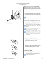
A
1.
1.
2.
A
2.
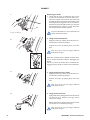
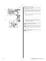
FOOTRESTS
ONE-PIECE
Tools: 5 mm Allen Key
1. Footrest, one piece
Adjust the angle by loosening the four screws (A)
on the footplate attachment with a 4 mm Allen
key. Adjust the footplate to the correct position
and retighten the screws.
Do not place anything on the footplate when
the screws have been loosened.
Tools: 4 mm Allen Key
10 mm fixed spanner
1. Footrest, one piece (XLT Swing)
Adjust the angle and the depth by loosening the
two screws (A) on the footplate attachment with
a 5 mm Allen key. Adjust the footplate to the cor-
rect position and retighten the screws.
Do not place anything on the footplate when
the screws have been loosened.
2. The footrest can be flipped up. Lift the left side of
the footrest upwards.
Be careful not to trap your fingers between
the footrest and the receiver when you fold
down the footrest.
2. The footrest can be flipped up. Lift the right side
of the footrest upwards.
Be careful not to trap your fingers between
the footrest and the receiver when you fold
down the footrest.

13
INVACARE
®
XLT Service Manual
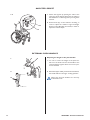
1.
2.
1. Adjusting the seat depth
Lift up the front part, slide into required depth.
SEAT
2. Adjusting the shape
(tension adjustable seat)
Use the straps underneath the seat to adjust the
shape of the seat. Always have a cushion on the
seat when testing its adjusted shape.

14 INVACARE
®
XLT Service Manual
1.
3.
2.
4.
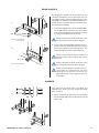
BACKREST
Angle adjustment
1. The backrest can be mounted in two different
positions, each with the possibility to change the
angle of the backrest. The angle is infinitely variable
by ±10 degrees.
The backrest tube has an 8 degree bend towards
the back.
2. If you want to tilt the backrest forwards, position
the eccentric (hexagon) plate in the position fur-
thest back (as in the illustration). You can then
adjust the tilt of the backrest to maximum –10°.
3. If you want to tilt the backrest backwards, posi-
tion the eccentric (hexagon) plate in the position
furthest to the front. You can then adjust the
angle to maximum +10°.
4 Move the eccentric (hexagon) plate by loosening
the socket cap screw on the plate. Hold the inner
nut firmly in place using a 10 mm fixed spanner.
Remove the plate, push the backrest to the desired
angle, move the plate forwards or backwards and
mount it in that position. Hold the nut steady from
the inside, and retighten the socket cap screw with
the Allen key.
Tools: 4 mm Allen Key
10 mm fixed spanner

15
INVACARE
®
XLT Service Manual
2.
3.
1.
B
A
B
A
Tools: 4 mm Allen key
10 mm fixed spanner
Tools: 24 mm fixed spanner
Angle adjustment, fine adjustments
When you have decided the direction in which you
want to tilt the backrest, it is time to make the fine
adjustments, i.e. adjusting the backrest to suit your
body. Proceed as follows:
1. Loosen the four nuts (B) on the inside of the
backrest tubes with 1- 2 turns with a 10 mm fixed
spanner. Hold screws (A) firmly in place with a
4 mm Allen key.
2. Then, using a 24 mm fixed spanner, turn the plates
– a little at a time, first on one side of the chair,
then on the other side. By this alternating proce-
dure, you can adjust the tilt of the backrest.
Note! You must alternate between the two plates
whenever you turn them, otherwise, the backrest
could become twisted, and its ergonomic advantages
will be lost.
3. Once you have found the right position, retight-
en the nuts on the inside. Hold the screws (A)
firmly in place with the Allen key.
Tools: 4 mm Allen key
10 mm fixed spanner
The tip risk increases the further back the
backrest is tilted. We recommend the use of
anti-tip devices.

16 INVACARE
®
XLT Service Manual
4.
A
B
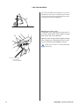
Height adjustment
With the height-adjustable backrest it is possible to
adjust the backrest height to suit the user without
changing the backframe. Proceed as follows:
Loosen and remove screws (A) and the small plastic
bracket (B) on the back of the back support. Adjust
the backrest extension to the desired height and refit
the screws.
Tools: 4 mm Allen key
4. Adjust the shape of the backrest by adjusting the
Velcro straps.
The user should be seated in the chair when the
Velcro straps are adjusted. When adjustment is
complete fold the backcloth back into position
and secure it with the Velcro straps.
When you loosen the backrest, the tip-risk
increases. We recommend the use of anti-tip
devices.
For backrest heights of more than 35 cm use a back-
rest extension.

17
INVACARE
®
XLT Service Manual
1.
A
2.
3-4.
B
D
C
5.
F
Adjusting the height of the armrests
1. Flip up armrest
If your chair is equipped with armrests that can be
raised or lowered, this is achieved by loosening the
screw (A), moving the armrest into the required
position and retightening the screw.
When adjusting the height, do not place
your fingers between armrest pad and side
plate as they may get trapped.
ARMRESTS/MUDGUARD
2. Detachable armrest
If your chair is equipped with armrests that can
be raised or lowered, this is achieved by pulling
up the armrest and loosening the screw (B) under
the armrest. Move the screw up or down to the
desired position and retighten the screw. Lower
the armrest again.
When adjusting the height do not place your
fingers between seat tube and side plate as they
may get trapped.
Tools: 5 mm Allen key.
Tools: 5 mm Allen key.
3. Mudguard
Adjust the height of the mudguard by pulling up
the mudguard and loosening the screw (C). Move
the screw up or down to the desired position and
retighten the screw. Insert the mudguard again in
it's attachment.
When adjusting the height do not place your
fingers between seat tube and side plate as they
may get trapped.
4. To adjust the depth of the mudguard, unscrew
screws (D) using an Allen key. Move the mudguard
into the required position and fasten the screws
again.
Tools: 3 mm Allen key
5 mm Allen key
5. Adjusting the play
The armrests and mudguards are equipped with
adjustable supports that enables you to reduce the
play when pulling up or pushing down the tubes.
Tighten or loosen the screws (F) in the four cor-
ners as needed.
Take care not to loosen the two middle screws.
These attach the supports to the frame.
Take care that your fingers do not get caught
between armrest/mudguard and tyre.
Tools: 5 mm Allen key.

18 INVACARE
®
XLT Service Manual
1.
A
4.
3.
2.
B
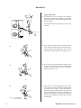
Adjusting the brake
1. Check that the tyres are inflated to the correct
air pressure as indicated on the side of the tyre.
Then use an Allen key to loosen the screws (A)
and slide the brake and brake attachement to the
desired position and tighten. The correct distance
between the brake pin (B) and the tyre, when the
brake is disengaged, is approx. 15 mm. The brake
pin should be in a horizontal position.
Incorrect adjustments or use of the brake can
reduce their performance.
3. Using the Performance brake
Apply the brake by pushing the brake lever for-
wards until it reaches the stopper.
Release the brake by pulling back the brake
lever.
Take care not to trap your fingers between
brake shaft and tyre.
BRAKES
4. Using the Active brake
Apply the brake by pulling the brake lever forwards
(on the side of, or between your legs) until it
reaches the stopper.
Release the brake by pushing the brake lever back
(on the side of, or between your legs).
Take care not to trap your fingers between
brake shaft and tyre.
2. Using the Standard brake
Apply the brake by pushing the brake lever for-
wards until it reaches the stopper.
Release the brake by pulling back the brake
lever.
Take care not to trap your fingers between
brake shaft and tyre.
When the standard brake is applied, the brake lever
can be pushed backwards without disengaging the
brakes.
This is to prevent the brakes from accidentally dis-
engaging during transfer to and from the wheelchair.
Tool: 5 mm Allen key

19
INVACARE
®
XLT Service Manual
2.
D
C
1.
A
B
A
B
1.
REAR WHEELS
The tip risk increases if the rear wheels are
located in front of the backrest. Use anti-tip
devices.
Always remember to adjust the brakes, when
the rearwheel position has been changed.
When you have fitted the wheels in the cor-
rect position, it is important that you check
thoroughly that the nuts and screws are
tightened securely. This is important for your
own safety!
Tools: 24 mm spanner
Tools: 5 mm Allen Key
10 mm spanner
By changing the position of the rearwheel on the
rearwheel attachment you can alter both the rear
seat height and the manoeuvrability/stability of the
wheelchair. The further forward the rearwheel is posi-
tioned, the more manoeuvrable your chair becomes,
but with reduced stability.
1. To alter the height position of the rearwheel plate,
use an Allen key to hold the screws (A) in place
and loosen nuts (B) with a fixed spanner. Choose
the new position and fasten the screws.
Always remember to adjust the brakes, when
the rearwheel position has been changed.
2. To move the rearwheel (either backwards or for-
wards) on the rearwheel attachment, first remove
the nut (C), adjust the axle housing (D) to the
required position and then refasten the nut.
CAMBER
The cambered rearwheel plate is mounted and
adjusted in the same way as the original rearwheel
plate, see above.
1. Make sure that the rib (A) on the rearwheel plate
and the chamfer (B) on the camber block is placed
downwards.

20 INVACARE
®
XLT Service Manual
90
º
C
A
B
CASTOR WHEELS
Tools: 4 mm Allen key
5 mm Allen key
10 mm fixed spanner
The manoeuverability of the wheelchair is very much
dependent on the castors and their position relative
to the ground surface. The angle between the castors
and the ground should be 90 degrees.
Adjusting the castor angle
To adjust the castor angle, loosen nuts (A) with 1-2
turns with a fixed spanner, while holding screws (B)
firmly in place with a 4 mm Allen key.
Adjust the castor housing to desired angle by inserting
the 5 mm Allen key in the hexagon hole (C) and tur-
ning it to the desired angle. Retighten nuts (A).
Check that the castor is securely fitted after
replacement.
Page is loading ...
Page is loading ...
Page is loading ...
Page is loading ...
Page is loading ...
Page is loading ...
Page is loading ...
Page is loading ...
Page is loading ...
Page is loading ...
Page is loading ...
Page is loading ...
Page is loading ...
Page is loading ...
Page is loading ...
Page is loading ...
Page is loading ...
Page is loading ...
Page is loading ...
Page is loading ...
-
 1
1
-
 2
2
-
 3
3
-
 4
4
-
 5
5
-
 6
6
-
 7
7
-
 8
8
-
 9
9
-
 10
10
-
 11
11
-
 12
12
-
 13
13
-
 14
14
-
 15
15
-
 16
16
-
 17
17
-
 18
18
-
 19
19
-
 20
20
-
 21
21
-
 22
22
-
 23
23
-
 24
24
-
 25
25
-
 26
26
-
 27
27
-
 28
28
-
 29
29
-
 30
30
-
 31
31
-
 32
32
-
 33
33
-
 34
34
-
 35
35
-
 36
36
-
 37
37
-
 38
38
-
 39
39
-
 40
40


Invacare XLT Dynamic User manual
- Type
- User manual
- This manual is also suitable for
Ask a question and I''ll find the answer in the document
Finding information in a document is now easier with AI
Related papers
-
Invacare XLT Active User manual
-
-
-
-
-
-
-
-
-
Other documents
-
Shine Company 4617DB Operating instructions
-
-
Etac Cross XL User manual
-
-
Vermeiren Alesia User manual
-
Etac Next Comfort User manual
-
Etac NEXT User manual
-
Etac Act User manual
-
 BestMassage B075XJMMPQ Installation guide
-
Etac Cross User manual
