Etac Cross XL User manual

Type
User manual
74236M 2015-11-06
Cross XL
Manual English
2
Heading Page
1. General .............................................................................................. 3
2. Handling/Transport ......................................................................................... 4-6
3. Product Description Cross XL .......................................................................... 7
4. The chairs possibilities ..................................................................................... 8-10
5. Accessories .............................................................................................. 11-13
6. Settings Seat ....................................................................................... 14-16
7. Backrest mod. 2 ..................................................................... 17-18
8. Backrest 3A ........................................................................... 19-23
9. Legrests .................................................................................. 24-26
10. Driving technique/Manoeuvring .............................................. 27-32
11. Assembly instructions, Accessories .................................................................. 33-35
12. Care and maintenance/Fault-finding chart ...................................................... 36-37
13. Tests and Guarantees ...................................................................................... 38
14. Alternative Seat heights/Angles....................................................................... 39
15. Weights and Measurements/Standard models ................................................. 40-41
Contents
2 3
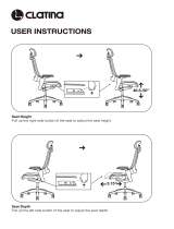
Cross XL is a manual, cross-folded, extra wide allround chair with multiple functions and is intended
for use both outdoors and indoors. The seat is adjustable in height, angle and depth. The backrest is
adjustable in height, angle and shape. The footrests are adjustable in height, angle and depth.
Cross XL can be supplemented and adjusted if needs change. A large range of options and accesso-
ries are available: Various types of backrest and legrest, fixing points for transport in mobility service
buses, anti-tips, and various types of handrims and brakes etc.
Cross XL has the best prerequisites to create comfort, functionality and good manoeuvrability.
Crash test
Etac’s wheelchairs are tested in accordance with ISO 7176-19 and ISO 10542. These ISO standards
specify requirements for the design of the wheelchair’s restraint points, how the wheelchair and the
user are secured in the vehicle, and also describe how tests should be carried out and how the test
results should be interpreted. Etac’s wheelchairs are crash tested at the Technical Research Institute
of Sweden. The tests were carried out with normal settings on the wheelchairs (see manual for the
respective wheelchair) and with an UNWIN_WWR/ATF/K/R restraining device and an UNWIN_WWR/
HD/ATF/K/R 3-point belt.
The cross-folded wheelchairs Cross, Twin and Transit were supplemented with securing points.
Seat widths: From 47,5 cm to 60 cm.
Max. user weight: 155 kg
Service life: The product is tested and fulfils the demands stated in EN 12183. The main product’s
durability and lifetime is at least five years when used in accordance with intended use, the safety in-
structions, the reconditioning manual and instructions for use in the user manual. The main product
consists of the chassis for seat and back support. Additional parts/accessories are handled in accord-
ance with the manual and reconditioning manual. The actual lifetime can vary, depending on how
much and how intensively the product is being used, but a maximum of 10 years. If the product is
intended for use after the service life period specified by Etac, it is the responsibility of the product
owner to ensure product functionality in accordance with the manual and reconditioning instruc-
tions. If this cannot be ensured then the product should be taken out of use.
1 General
The manual must be read thoroughly to avoid damage when handling and using the Cross XL chair.
is a warning triangle to indicate that special care should be taken.
(!) provides advice and tips worth considering
Anti-tips available as an accessory. At the correct setting they will prevent the wheelchair from tipping back
wards.We recommend all users to use the anti-tip devices, unless you are an experienced user
with absolute control over your wheelchair.
The tool kit contains: 5 Allen keys: 6, 5, 5, 4 and 3 mm
3 Ring spanners: 13, 10 and 8 mm
1 Socket spanner: 24/19 mm
1 Phillips screwdriver
The following methods of surface treatment have been used:
Lacquered surfaces=Polyester powder coating
Non-lacquered aluminium parts=Anodized coating
Non-lacquered steel surfaces=Galvanized
4
2:1 Folding
- If a steering bar and/or cross brace is mounted,
they should be removed.
- Flip up the footrests.
- Lift up the seat, see illustration.
2:2 Unfolding
- Push down on one side of the seat frame, using the whole of the
flat of the hand, see illustration.
Do not hold the seat frame tube while unfolding as there is a risk
of pinching your fingers.
2:3 Lifting the wheelchair
Wheelchair without lockable legrests:
- Flip up the footrests and swing the legrests in under the seat, or
remove them completely.
- Lift by holding the push handles and the front part of the frame by
the legrest mounting point.
Wheelchair with lockable legrests:
- Lift using the push handles and legrests.
Before lifting, ensure that the height adjustable push handles are
securely fastened.
2:4 Transportation in vehicles
Private car/taxi: The wheelchair should be placed in the car boot. If this is
not possible, ensure that the wheelchair is placed safely in the back seat, so
that it is not able to overturn or roll. If possible secure the wheelchair with
the car’s safetybelt.
2 Handling/Transport
4 5
2 Handling/Transport
2:5 Securing
The wheelchair must be secured as follows, the straps must not be put
through the wheels or around the back tubes.
2:6 Seat belt
If the wheelchair is used as a seat for travelling Etac recommends that the
user wears the 3-point seat belt that is fitted in the vehicle. It is important
that the 3-point belt is fitted correctly, as in the illustrations:
2:7 Recommendations
Etac recommends in the following order:
1) The user transfers to a seat in the vehicle and uses the vehicle’s 3-point
belt while travelling. The wheelchair is then placed in the boot or safely in
the back seat so that it cannot overturn or roll.
2) The wheelchair is secured facing forwards in the vehicle as per this
manual, the user uses a separate 3-point belt that is secured in the vehicle.
This is the way in which the wheelchair is tested and approved according to
the ISO-standard for crash testing of wheelchairs in vehicles.
3) According to directive 2001/85/EC, appendix VII, point 3.8.3. there are
specially marked wheelchair locations in vehicles that permit transport with
a wheelchair facing in the opposite direction of travel. If this means of travel
is used, the user/carer must be aware while travelling, prepared for sud-
den movements and have the capacity to maintain a safe sitting position
throughout the entire journey. The user’s disabilities must not be of such an
extent that he/she is not able to hold onto the handles fitted in the vehicle
when there are changes of speed or direction.
In conjunction with points 2 and 3:
- a positioning belt should be used
- a correctly adjusted headrest should be used
- the backrest should be level with or above the user’s shoulders
- the parking brake should be used
- the anti-tips should be lowered
300mm
25°
25°
10°
10°
300mm
6
2 Handling/Transport
2:8 Warning
- The wheelchair’s positioning belt is not sufficient to prevent the user from
being thrown out of the wheelchair in the event of sudden braking.
- The restraining device must not be passed through the wheels or around
the back tubes.
- Options/accessories that can be removed without tools, such as trays,
must be removed and secured or placed where they cannot fly around
inside the vehicle in the event of a collision.
- If the wheelchair has been involved in a collision in a motor vehicle, it
should be inspected at a Technical Aids Centre or by Etac before being
used again.
6 7
1 Push handles 12 Front fork attachment
2 Backrest cover 13 Protective stopper
3 Backrest upholstery 14 Cross
4 Seat upholstery 15 Side frame
5 Brake 16 Armrest attachment
6 Footrest 17 Quick release hub
7 Widened footrest 52.5-60 18 Handrim
8 Footrest locking knob 19 Rear wheel
9 Legrest 20 Back tube
10 Castor wheel 21 Locking knob, push handles
11 Front fork 22 Cross brace
3 Product description Cross XL
3
6
7
14
17
15
19
18
20
10
11
13
4
5
16
8
9
12
1
2
21
22
8
4 The chairs possibilities
Seat height
Seat angle
Castor wheel
Front fork
Rear wheel
Handrims
Seat
Backrest
Cross back 2
Seat depth
(functional)
Rear Front
40-50 cm 40-51 cm
Max forward angle: 2 cm lower front than back.
Max backward angle: 6 cm higher front than back.
6" half-massive/ 6,5" massive
Short/medium, with 3 alternative height positions
for the castor wheel
20", 22" or 24"
High-pressure 1"
Low- pressure 1 3/8"
Solid
Camber angle 2° or 0°
Stainless, plastic coated, cellular rubber, aluminium
Black fabric/hard seat/ECS
(ECS, a fixed seat/backrest system with
anatomically shaped cushions, detachable)
Type Height Backrest angle
standard 30-45 cm -5
o
- +15
o
high 38-55 cm -5
o
- +15
o
Short frame 36-42 cm. Long frame 42-48 cm.
Short frame 42-48 cm. Long frame 48-54 cm.
Seat height rear
Seat height front
8: 6 Sittsdjup
Seat depth
Functional seat depth
8 9
Ryggrest Cross-
back 3A
Seat dept
(functional)
Backrest
upholstery
Backrest cover
Push handles
Fixed
push handles
Legrests,
detachable,
adjustable side-
ways
Angle adjustable
Type Height Backrest angle
Monoangular 32-45 cm -5
o
- +20
o
Biangular 32-45 cm -5
o
- +20
o
Triangular 32-45 cm -5
o
- +20
o
Lumbal angle
Monoangular +10° (fixed)
Biangular ±6
o
(at 10
o
back angle)
Triangular ±12
o
(vid 10
o
back angle)
Short frame 36-42 cm. Long frame 42-48 cm.
Short frame 42-48 cm. Long frame 48-54 cm.
Triangular +0 to 6 cm.
Adjustable plush upholstery/ECS
Standard/Comfort/Tidy
Push handles/alternative bow handle
Both height adjustable at intervals of 2 cm.
Detachable.
Fits for Crossback 3A
Right/left model
Standard knee angle/narrow/narrow short
Lockable, standard knee angle/narrow/narrow
short
Mod 1 with calf support adjustable in height,
depth, angle and sideways (also available with
flip-up calf support).
Mod 2 with calf support adjustable in angle,
height and sideways.
Mod 3 with foldable calf support from 40 cm
seat width.
With attachment and calf support
4 The chairs possibilities
Seat depth
+ 6 cm
Functional seat depth
1
1
5
5
10
4 The chairs possibilities
Armrest
Footrest
Front fork
attachment
Brakes
Single hand
drive
Plaster legrest/amputee legrest/
amputee weight
short 25 cm/long 35 cm
Std Max length: 51 cm.
Min length: 33 cm.
Extended attachment tubes +10 cm
Shorter attachment tubes -8 cm
One-piece footrest
One-piece footrest complete for 35-37,5 seat
width, adjustable in angle, settable height and
depth
Standard/widened 6 cm
Adjustable 4 cm in height
Standard/Single hand brake, both alternatives
with standard, angled or extended handle.
For right or left side. Telescoping axle, easy to
remove when folding
+ 6 cm
10 11
5 Accessories
Armrest height-adjustable 25 cm long, solid top, black
Armrest height-adjustable 38 cm long, solid top, black
Armrest cover detachable, 25 or 38 cm long
padded or gel, dark grey plush or black Dartex
Armrest cushion wide and soft, 8x40 cm, fits onto armrest
Armrest cushion Hemi swing-away for mounting on long armrests
Armrest foldable height adjustable or fixed height
Side guard black
Mudguard right and left
Thigh support
Widening kit to extend handrims, brake and armrests 10 mm on each side
Tray transparent, fits onto long armrest
Tray Hemi tip up right / left
Bracket for seat extension
Seat cushion dark grey plush and black velour, 56 cm, cut according to seat depth set,
washable
12
5 Accessories
Seat cushion Tidy, water repellent, wipe clean
Comfort wedge for the cushion, evens out the front part of the seat
Seat and backrest cushions ECS in PE or memory foam, cover in dark-grey plush or
black Dartex
Cover for calf support on angle adjustable legrest model 3
Calf strap detachable, black nylon, adjustable in length
Padding for calf strap
Heel straps black nylon, adjustable length
Extended footrest fits onto the existing footrest
Positioning belt two pieces, with snap-lock, fixing points on the wheelchair frame
Seat belt with snap lock
Headrest mounts on steering bar, adjustable in height, depth and angle
Available in several models
Back wedge length 15 and 30 cm, attached with Velcro
Trunk support settable in depth and angle, black Dartex, foldable, incl. attachment
Trunk support Cross back 3A, PUR or Dartex
Trunk support Cross back 3A, swing-aside, medium or large cushion
Anti-tips foldable, height settable
A
12 13
5 Accessories
Rain cape Proof
Weather protector Proof
Leg warmer Proof
Gloves
Bags Case Logic
Bags
Anti-tips telescopic, foldable, settable height, adjustable length and angle
Anti-tips with tilter, foldable, height settable
Tilter (not for low seat heights 20" / 22" in position C)
Cane holder two parts, one of which is an elasticated section that is fastened
around the cane.
Spoke guard with grey or yellow print
Tetra quick release adapter for persons with reduced hand function
Transport attachment when mounted in C4 position only with 0
0
camber + spacer 20232
Tool kit
Information about bags, gloves and clothes is available at www.etacbutiken.com
14
6 Settings seat
6:1 Front seat height
The front seat height (see Part “The chairs possibilities”) is dependent on:
Castor wheel 6", 6.5".
Front fork attachment Settable height and angle.
Front fork Short and medium length with three alternative
height settings for the castor wheel.
Risk of tipping: Always check the positioning of
the anti-tips.
(!) See also point 14: “Alternative seat heights/angles”.
6:2 Castor wheel
The height may be adjusted by changing the castor wheel itself or by chang-
ing its position in the fork. Unscrew the castor wheel and place it at the
desired height in the front fork.
Tools: 5 mm Allen key and 10 mm U-spanner.
(!) Also adjust the angle of the front fork attachment, see point 6:5.
6:3 Adjusting the height of the front fork attachment
The height of the front fork can be adjusted 4 cm up or down by loosening
the two attachment screws (A and B) 1-2 turns. See position marking (C) to
obtain equal height on both sides. Check and adjust the angle of the at-
tachment and tighten the screws.
Tools: 6 mm Allen key (a spirit level may be useful).
Risk of tipping: Always check the positioning of the anti-tips.
(!) Also adjust the angle of the front fork attachment, see point 6:5.
6:4 Changing front fork
Pull out the plug attachment on the front fork attachment to reach the
retaining nut. Unscrew the nut and pull out the front fork. Take the washer
and ball bearings and put it on the new fork (the bevelled side (A) towards
the fork). Insert the new fork into the attachment. It is also important to en-
sure that the washers in the attachment (under the retaining nut) are placed
in the right order, with the spring washer (B) on top.
Tighten the retaining nut until it cannot be turned any more. Loosen it 1/2-1
turn. The spring washer then has the correct tension. It reduces the risk of
the castor starting to “wobble”.
Tools: 19 mm socket spanner.
(!) Also adjust the angle of the front fork attachment, see point 6:5.
A
B
C
A
B
20Nm
14 15
6:5 Setting the angle of front fork attachment
The correct angle setting is important for the wheelchair’s manoeuvrability.
- Loosen the lower attachment screw(A) about 2 turns so that the tag (C)
moves freely inside the shaft.
- Insert the Allen key in the hole (B) and turn until the attachment is at
90° to the floor.
- Always start from a position that enables the wheel to move forward
in the rotation (D).
- Hold the shaft in place while the lower attachment screw is tightened.
Tools: 6 mm Allen key (a spirit level may be useful).
(!) Keep your eye on something vertical, e.g. a doorpost or a table leg
when setting the angle.
Risk of tipping: Always check the positioning of the anti-tips.
6:6 Rear seat height
The rear seat height is dependent on:
The size of the rear wheels 24", 22" or 20"
The position of the rear wheels, 3 alternative heights: A-B-C
Risk of tipping: Always check the positioning of the anti-tips.
(!) See also point 14: “Alternative seat heights/angles”.
6:7 Rear wheel with quick release hubs
The shaft axle is movable and can also be adjusted in length. Turn the nut on
the axle inwards/outwards while at the same time holding the axle with an
adjustable spanner.
When attaching the rear wheels, always check that they are securely
mounted. The button in the hub should pop out to the original position.
6:8 Height adjustment of the rear wheels
Loosen the hub sleeve, washers and nuts and reassemble it at the desired height.
At the same time you should also test for correct balance, see point 9:8.
Tools: 24 mm socket spanner.
-Check that the rear wheels are correctly mounted, see point 6:7.
-Always check the positioning of the anti-tips.
-Always adjust the brakes after re-positioning the rear wheels.
(!) Also adjust the angle of the front fork attachment.
6 Settings seat
A
B
Seat height rear
C
B
A
C
D
20Nm
16
Seat height rear
Seat height front
Seat depth
Functional seat depth
6 Settings seat
6:9 Adjusting the brakes
The brakes are infinitely settable.
- Loosen the nut (A) a couple of
turns and slide the brake until
the brake block is about 15-20
mm from the tyre when the
brake is not applied.
- Ensure that the brake is posi-
tioned straight in the groove
and tighten the nut appr. 5 Nm.
Test the brakes.
Tools: 5 mm Allen key.
If the rear wheel is positioned in
one of the forward settings it is
possible for a legrest, when swung
to the side, to unlock an applied
brake. To avoid this the brake han-
dle should be adjusted so that you
attain a “neutral” position. In this
way the brakes are released only
when the handle is pushed close
to the wheel.
- Loosen the screw on the inside
of the brake handle.
6:10 Seat angle
The seat angle is dependent
on the difference between the
front and the rear seat heights.
The seat can also be set angled
forwards.
For max. angle of the chair, see
“The chairs possibilities”.
Bear in mind the risk of tipping, always adjust
the position of the anti-tips.
6:11 Seat depth Cross XL with adjustable seat upholstery
The seat depth can be adjusted
(Also see “The chairs possibili-
ties”)by lifting the front seat up-
holstery and sliding it backwards
or forwards.
With Cross backrest 3A
triangular, the seat depth can be
further adjusted by means of the
lumbar angle (see the settings
section for Cross backrest 3A).
Brake lever extensions and
angled brake handles are
available as accessories.
- Remove the oval plate, turn
it 180°(the pins on the plate’s
inside must sit in the upper hole)
and tighten it again.
Tools: Phillips screwdriver.
The braking effect is de-
pendent on the air pressure
in the tyres.
The brakes are parking
brakes and should not be
applied during use.
(!) If the seat angle is changed:
- Adjust the angle of the
front fork attachment.
- Also check the angle of
the backrest.
(!) The functional seat depth is
dependent on the setting of
the back upholstery. It can be
upto 6 cm longer than stated
seat depth measured from
the seat tube.
The brake does not work
with 20" low pressure or
solid tyres in pos. A3, B4
or C4.
A
16 17
7:1 Backrest
The backrest is settable in height and angle and has adjustable backrest up-
holstery.
Risk of tipping: Always check the position of the anti-tips after ad-
justing the backrest.
7:2 Backrest height
The backrest height is continuously settable (See “The chairs possibilities”).
Loosen the screws (A) 2-3 turns to set the height of the backrest.
Ensure that both sides are at the same height by checking against the ruler
(B) on the back of the back tube. Tighten the screws securely.
Tools: Allen key 5 mm.
7:3 Backrest angle
The backrest angle is infinitely variable (See “The chairs possibilities”).
The angle is adjusted using the nut on the inside of the rear wheel attach-
ments.
- Loosen the nut on one of the back tubes, set the desired angle and
tighten the nut firmly again.
- Repeat the procedure on the other side.
Tools: 13 mm ring spanner.
(!) Check that the angle is the same on both sides by comparing the
distance between the back tube and the armrest guard.
Risk of tipping: Always check the positioning of the anti-tips when
changing the backrest angle.
7 Settings backrest mod. 2
18
7:4 Backrest upholstery
The contour of the backrest upholstery is individually adjustable by using
the five Velcro straps and the backrest cover.
- Allow the cover plenty of room between seat and backrest, so that
it is possible to “sit in” against the backrest.
- Loosen all the straps and ensure that the user is sitting as far back in
the seat as possible.
- Tighten the straps so that they follow the contours of the back and
give support to the lumbar region.
Risk of tipping: Always check the positioning of the anti-tips after
adjusting the backrest upholstery.
(!) Do not over-tighten the upper Velcro straps as this can prevent the
cross-brace from unfolding properly, i.e. the back tubes do not sit
flush in the side-frames.
7:5 Height adjustable push handles
The push handles can be set at intervals of 2 cm.
- Loosen the knob (A) and press the plastic washer. Install desired
height.
- Ensure that the push handles are locked in the correct position.
Tighten the knob again.
Ensure that the knobs are properly tightened. This is especially im-
portant if you intend to lift the wheelchair whilst the user is sitting in
it.
7:6 Cross brace, backrest (standard on Cross XL)
A cross brace is fitted to the backrest for extra stability. The cross brace is
fixed to the push handles and can easily be removed using the snap lock.
The cross brace must be uncoupled if the chair is to be folded.
7:7 Bow handle
The steering bar is height adjustable and detachable. It is mounted in the
push handle attachment, and is adjusted in the same way, see point 7:5. A
headrest may also be fitted to the steering bar, see part “Assembly instruc-
tions, Accessories”.
The steering bar must be removed before the chair can be folded.
Ensure that the knobs are properly tightened. This is especially
important if you intend to lift the wheelchair whilst the user is
sitting in it.
7 Settings backrest mod. 2
18 19
8 Settings backrest 3A
1
3
2
8:1 Adjusting back support angle, mono- bi- and triangular back
1. Loosen the nut.
2. Adjust the back support angle. Use the posi-
tion markings to obtain the same back support
angle on the right and left sides respectively.
3. Tighten the nut.
Risk of tipping: Always
check the positioning of
the anti-tips after adjusting
the backrest upholstery.
Tools: Ring spanner 13 mm.
20
1
1
5
5
1
1
5
5
5
1
1
5
1
1
2
3
4
5 6
8 Settings backrest 3A monoangular back
8:2 Adjusting back support height
1. Remove the protective cover.
2. Loosen the locking screws max. 1 turn.
3-4. Adjust the back support height using
the graduation and marking on the lower
back rod.
5. Tighten the locking screws.
6. Fit the protective cover.
1
Risk of tipping: Always
check the positioning of
the anti-tips after adjusting
the backrest upholstery.
Tools: Allen key 5 NV.
  • Page 1 1
  • Page 2 2
  • Page 3 3
  • Page 4 4
  • Page 5 5
  • Page 6 6
  • Page 7 7
  • Page 8 8
  • Page 9 9
  • Page 10 10
  • Page 11 11
  • Page 12 12
  • Page 13 13
  • Page 14 14
  • Page 15 15
  • Page 16 16
  • Page 17 17
  • Page 18 18
  • Page 19 19
  • Page 20 20
  • Page 21 21
  • Page 22 22
  • Page 23 23
  • Page 24 24
  • Page 25 25
  • Page 26 26
  • Page 27 27
  • Page 28 28
  • Page 29 29
  • Page 30 30
  • Page 31 31
  • Page 32 32
  • Page 33 33
  • Page 34 34
  • Page 35 35
  • Page 36 36
  • Page 37 37
  • Page 38 38
  • Page 39 39
  • Page 40 40
  • Page 41 41
  • Page 42 42
  • Page 43 43
  • Page 44 44

Etac Cross XL User manual

Type
User manual

Ask a question and I''ll find the answer in the document

Finding information in a document is now easier with AI