
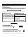
WARNING: If the information in these
instructions are not followed exactly, a fire or
explosion may result causing property damage,
personal injury or loss of life.
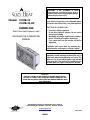
Models #CMB-31
#CMB-31-RF
CAMBRIDGE
Direct Vent Gas Fireplace Insert
INSTALLATION & OPERATING
MANUAL
Do not store or use gasoline or other flammable vapors
and liquids in the vicinity of this or any other appliance.
WHAT TO DO IF YOU SMELL GAS:
‚ Do not try to light any appliance.
‚ Do not touch electrical switches; do not use the
phone in your building.
‚ Immediately call your gas supplier from a neighbor’s
phone. Follow the gas supplier’s instructions.
‚ If you cannot reach your gas supplier, call the fire
department.
- Installation and service must be performed by a
qualified installer, service agency or the gas supplier.
This appliance may be installed in an aftermarket
permanently located, manufactured home (USA only) or
mobile home, where not prohibited by local codes. This
appliance is only for use with the type(s) of gas indicated
on the rating plate. This appliance is convertible for use
with other gases, an LP gas conversion kit is included.
IMPORTANT:
READ ALL INSTRUCTIONS CAREFULLY BEFORE INSTALLATION.
FAILURE TO INSTALL THIS FIREPLACE INSERT CORRECTLY CAN
CAUSE SERIOUS STRUCTURAL AND FIRE HAZARDS AND MAY VOID
YOUR WARRANTY.
This fireplace may be covered under one or more of
the following U.S. Patents: #5,931,154 , #6,004,493, #6,029,655
www.kozyheat.com
April 2006
INDEX

Fireplace Insert Specifications ............................................................... 1
Safety Requirements..................................................................... 1-2
Requirements of Existing Fireplace ........................................................... 2
Fireplace Insert Components ................................................................ 3
Preparing The Existing Fireplace ............................................................. 4
Gas Line Installation Requirements - Minimum/Maximum Pressures................................ 5
Insert Preparation......................................................................... 6
Remove the Glass Assembly ....................................................6
Remove the Air Duct ..........................................................6
Fan Installation ......................................................................... 7-8
Model #CMB-31.............................................................. 7
Model #CMB-31-RF........................................................... 8
Installing the Insert .................................................................... 9-14
Co-Linear Vent System .................................................... 9-11
Position the Insert & Floor Protector ......................................... 11-12
Secure the Air Duct .......................................................... 12
Complete the gas line installation .............................................. 13
Check millivolt board installation ............................................... 13
Complete fan wiring installation (Models #CMB-31 & #CMB-31-RF) .................. 14
Assemble & Attach The Shroud.............................................................. 15
Install the lower grill......................................................... 15
Log Installation .......................................................................... 16
Complete the Installation -
Initial Lighting ....................................................................... 17
Replace the Glass Assembly ............................................................ 17
Thermostat - Remote Control - Wall Switch Installation (Model #CMB-31 only) ...................... 18
Model #CMB-31
Lighting & Shutdown Procedures............................................ 19-20
Manifold (outgoing) & Inlet (incoming) Pressure Check Procedures .................. 21
Model #CMB-31-RF
Lighting & Shutdown Procedures............................................ 22-23
Manifold (outgoing) & Inlet (incoming) Pressure Check Procedures................... 24
Maintenance Requirements ................................................................ 25
Millivolt Board Removal / Installation Procedures ........................................... 26-27
Troubleshooting Guide ................................................................. 28-29
Replacement Parts ....................................................................... 30
Warranty Policy ....................................................................... 31-32

Page 1
MODEL: #CMB-31 / #CMB-31-RF CAMBRIDGE
DIRECT VENT GAS FIREPLACE INSERT
INSTALLATION & OPERATING INSTRUCTIONS
IMPORTANT:
READ THIS MANUAL BEFORE INSTALLING AND USING THIS FIREPLACE
This fireplace has been tested to and complies with ANSI Z21.88-2005
CSA 2.33-2005 “VENTED GAS FIREPLACE HEATERS” by
OMNI-Test Laboratories, Beaverton, Oregon for U.S. & Canadian Installations. Installation must conform with local building codes
or in the absence of local building codes, with the National Fuel Gas code, ANSI Z223.1 NFPA 54 - Current Edition or the Natural
or Propane Installation Code, CSA B149-1.
SPECIFICATIONS:
Height (top of firebox): 19 1/4"
Width: 30" Back Width: 23 1/8 " Depth: 14 1/2”
Do not use this fireplace if any part has been under water.
Immediately call a qualified service technician to inspect
this appliance and to replace any part of the control
system and any gas control which has been under water.
COMMONWEALTH OF MASSACHUSETTS INSTALLATIONS
WARNING: This Product Must Be Installed By A Licensed Plumber
Or Gas Fitter When Installed Within The Commonwealth of
Massachusetts.
IMPORTANT: Installation of a CO detector is required in the
fireplace room.
WARNING: DO NOT REPLACE THIS BURNER WITH ANY
OTHER SIZED BURNER. REPLACEMENT WITH AN
UNAUTHORIZED BURNER CAN RESULT IN TEMPERATURES
EXCEEDING THE LIMITS FOR THIS UNIT AND VOID YOUR
WARRANTY.
DUE TO HIGH TEMPERATURES, THIS FIREPLACE SHOULD
BE LOCATED OUT OF TRAFFIC AND AWAY FROM
FURNITURE AND DRAPERIES
Warning: This Product Must be Installed By A Licensed
Plumber or Gas Fitter When Installed Within the
Commonwealth of Massachusetts
YOUNG CHILDREN SHOULD BE CAREFULLY SUPERVISED
WHEN THEY ARE IN THE SAME ROOM AS THIS FIREPLACE.
CHILDREN AND ADULTS SHOULD BE ALERTED TO THE
HAZARDS OF HIGH SURFACE TEMPERATURE AND SHOULD
STAY AWAY TO AVOID BURNS OR CLOTHING IGNITION.
CLOTHING OR OTHER FLAMMABLE MATERIAL SHOULD
NOT BE PLACED ON OR NEAR THE APPLIANCE
.

Page 2
The efficiency rating of this appliance is a product thermal efficiency rating determined under continuous operating
conditions and was determined independently of any installed system.
THIS INSERT IS APPROVED FOR INSTALLATION IN MASONRY AND FACTORY-BUILT SOLID FUEL BURNING FIREPLACES.
CAUTION: THIS APPLIANCE MUST NOT BE CONNECTED TO A CHIMNEY FLUE SERVING A SEPARATE SOLID-FUEL
BURNING APPLIANCE.
THE EXISTING FIREPLACE MUST MEET THE FOLLOWING
REQUIREMENTS:
1. The existing fireplace & chimney must be in clean and in
good working order and constructed of non-combustible
materials.
2. A gas line must be able to be installed to the insert.
3. Any chimney clean-outs must fit properly.
4. Existing Chimney:
Class ‘A’ metal chimney: 7” minimum inside diameter.
Masonry Chimney: 6" x 8" minimum inside diameter.
Existing chimney height: Minimum: 12 ft.
Maximum: 30 ft.
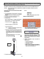
To Determine the length of your existing chimney:
A) Remove the chimney cap.
NOTE: It is helpful to have two people complete the next step
in determining chimney height:
B) With one person at the fireplace and the other person at the top
of the chimney, measure from the base of the fireplace to the
top of the chimney. Subtract 19½” for the height of the insert.
This is the total length of co-linear flexible aluminum you will
require.
MEASUREMENT FROM FIREPLACE BASE TO TOP OF CHIMNEY:_____
LESS 19½” (HEIGHT OF FIREPLACE):
-19½”
TOTAL CHIMNEY LENGTH REQUIRED: ______
5. The minimum inside dimensions of the existing fireplace
must be:
Height: 19 ½”
Front Width: 32”
Depth: 15 ¼”
Width at minimum depth location: 23 13/16"
MINIMUM OPENING DIMENSIONS
NOTE: The refractory / firebrick may be removed to
achieve minimum opening size requirements.
ZERO CLEARANCE FIREPLACE
INSTALLATIONS:
The floor of the existing fireplace may be removed to
achieve minimum opening size requirements. If this
method is used, the Kozy Heat Floor Protector kit, Part
#CMB-FLP, must be installed to protect any combustible
flooring exposed.
6. MINIMUM CLEARANCES FROM THE INSERT TO
COMBUSTIBLES:
• Insert side to sidewall: 10"
• Insert top to 10" mantel: 13”
• Insert top to 3/4" trim: 8"
• Bottom of insert to combustible floor in front: 3½”
• Bottom of insert underneath to combustible floor
using insulation shield #CMB-FLP: 0"
MIN. 12 FT.
MAX. 30 FT.

Page 3
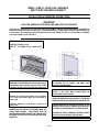
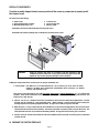
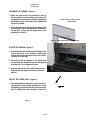
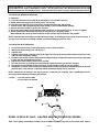
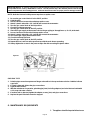
FIREPLACE COMPONENTS:
Check the assembly diagram below to ensure you have all the necessary components to properly install
this fireplace insert.
This insert includes the following:
1. Fireplace insert. 4. Co-linear air duct
2. Spring-loaded latch glass assembly. 5. Log set (See page #13)
3. Millivolt board with burner cover. 6. Refractory Panels
Model CMB-31 includes 150 CFM fan with limit switch and speed control.
Model CMB-31-RF includes modulating valve on millivolt board, fan kit and remote control.
4
6
2
3 1
WARNING: Failure to position the parts in accordance with the diagrams in this
installation manual or failure to use only parts specifically approved for this
appliance may result in property damage or personal injury.
Additional components which are necessary for proper installation are:
1. Vent System: Part #816-CL: For use with minimum 6” x 8” I.D. masonry or 8” I.D. Class ‘A’ metal
chimneys - Includes 12 ft. compressed, expandable to 30 ft. co-linear 3” x 3” flexible
chimney, and termination cap.
This insert is also approved for use with Dura-Vent,
Ameri-Vent, & Selkirk Metalbestos 3" x 3" Co-linear vent
systems. Refer to the instructions accompanying the vent system as well as the venting requirements and
instructions in this manual.
2. Shroud - 3 pc & 4 pc.: Standard shrouds are available for this insert and will fit most applications. Custom
shrouds may be ordered on a non-returnable basis. When ordering a custom shroud, please specify the
existing fireplace front opening height and width. An upper hood and lower grill is included.
3. Blank Shrouds - 3 & 4 pc. blank shrouds are available for on-site custom fit applications and are sized to the
opening after the insert has been installed. The interior perimeter is properly sized to fit onto the insert. The
outer perimeter must be cut, formed and finished (painted). An upper hood and lower grill is included.
4. Full door shrouds: Full door decorative shrouds are available for this insert and are used in place of a standard
or blank shroud.
A) PREPARE THE EXISTING FIREPLACE

Page 4
WARNING: CUTTING ANY SHEET-METAL PARTS OTHER THAN COMPONENTS LISTED IN THIS
SECTION, OF THE EXISTING FIREPLACE, IN WHICH THIS GAS FIREPLACE INSERT IS TO
BE INSTALLED, IS PROHIBITED.
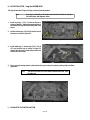
1) The refractory, glass doors, screen rails, screen mesh and log grates may be removed from the fireplace
before installing this gas fireplace insert.
2) Any smoke shelves, shields and baffles may be removed if attached by mechanical fasteners.
3) If necessary, remove the firebrick on the sides and back of the existing fireplace to obtain at least the
minimum opening requirements listed on page #2.
4) The fireplace flue damper can be fully blocked open or removed for installation of this gas fireplace insert.
5) ZERO CLEARANCE FIREPLACE INSTALLATIONS: The floor of the existing fireplace may be removed to
achieve minimum opening size requirements. If this method is used, the Kozy Heat Floor Protector kit,
Part #CMB-FLP, must be installed to protect any combustible flooring exposed.
6) Remove the existing chimney cap from the chimney.
7) Clean the chimney and inside of the fireplace to prevent creosote smell from entering the home.
8) Place ‘THIS UNIT HAS BEEN MODIFIED’ label in the bottom of the firebox so it will be visible if this gas
fireplace insert is removed.
B. RUN THE GAS LINE
CAUTION: Installation of the gas line must only be done by a qualified person in accordance
with local building codes.
IMPORTANT: DO NOT RUN THE GAS LINE IN A MANNER THAT WOULD OBSTRUCT THE
OPERATION OF THE FAN OR FAN COMPONENTS.
This fireplace is equipped with a 3/8" flexible gas line connection 18" long.
CAUTION: The manual shut off valve and millivolt board flexible gas line must not extend outside the insert
unit cavity. See the WARNING label affixed to the flexible gas line for additional installation
instructions and warnings.
1. Run the gas line into the fireplace, preferably through the left or right gas line hole provided. A gas line
knock-out is also located in the outer bottom of the insert when running the gas line through the bottom.
See Figure B-1 on page #5.
NOTE: If installing this insert into minimum opening dimensions, the gas line may need to be run after
the insert is in place due to space limitations.
If installing this gas fireplace insert into a factory-built fireplace and the factory-built fireplace
has no access holes(s) provided, an access hole of 1 ½" or less may be drilled through the
lower sides or bottom of the firebox in a proper workmanship like manner. This access hole
must be plugged with non-combustible insulation after the gas supply line has been installed.
IMPORTANT: An accessible shut off valve (included with the unit) must be installed up stream from the
regulator.

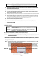
Page 5
Figure B-1
2. This fireplace is designed to accept either a 3/8"
or 1/2" gas line approved for gas appliances.
Consult local building codes to properly size the
gas supply line leading to a 3/8" reduction.
3. Connect the manual shut off valve to the
previous run gas line.
4. The gas line will be connected to the millivolt
board later in this manual.
IMPORTANT:
ALL CONNECTIONS WHETHER FIELD OR FACTORY MADE
MUST BE CHECKED FOR LEAKS.
NOTE: This appliance and its individual shut off valve
must be disconnected from the gas supply
piping system during any pressure testing of
that system at test pressures in excess of 1/2
psi.
NOTE: This appliance must be isolated from the gas
supply piping system by closing its individual
manual shut off valve during any pressure
testing of the gas supply piping systems at
test pressures equal to or less than 1/2 psi.
Pressure check taps for both the manifold (outgoing) and inlet (incoming) pressures are located in front of the
gas valve. The right pressure tap is the manifold pressure and the left pressure tap is the incoming pressure.
Follow instructions on page #21 for Model #CMB-31 and page #24 for Model CMB-31RF for checking these
pressures.
GAS SPECIFICATIONS
NATURAL GAS:
The minimum inlet gas supply pressure: 5.0 in. W.C.
Recommended inlet gas supply pressure: 7.0 in. W.C.
The maximum inlet gas supply pressure: 10.5 in. W.C.
Manifold Pressure: 3.5 in. W.C.
Manifold Pressure (lo setting): 1.7 in. W.C.
Orifice size (0-2000 ft): 37 Input rating: 27,500 BTU/Hr.
Minimum Input rating: 19,000 BTU/Hr.
Venturi setting: 1/8" open
LP GAS:
The minimum inlet gas supply pressure: 11.0 in. W.C.
Recommended inlet gas supply pressure: 11.0 in. W.C.
The maximum inlet gas supply pressure: 13.0 in. W.C.
Manifold Pressure: 10.0 in. W.C.
Manifold Pressure (lo setting): 6.5 in. W.C.
Orifice size (0-2000 ft): 52 Input rating: 28,000 BTU/Hr.
Minimum Input rating: 20,400 BTU/Hr.
Venturi setting: 1/2" open
For high altitude installations, consult the local gas distributor or the authority having jurisdiction for proper rating methods.
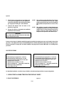
C. REMOVE THE FOLLOWING ITEMS FROM THE FIREPLACE INSERT:
1. GLASS ASSEMBLY: Figure C-1

Page 6
Air Duct
A) Locate the spring-loaded latches securing the
glass assembly (under the firebox).
B) While holding onto the glass frame, pull the
latch handles out, then down to release from
the clips on the glass assembly.
C) Lift the glass assembly up off the tabs at the
top of the firebox.
D) Pull the bottom of the glass assembly out and
remove.
E) Set aside where it will not be broken.
F) Remove the log package from inside the
firebox and set aside for installation later in
this manual.
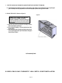
2. REMOVE THE AIR DUCT. Figure C-2.
A. Remove the air duct, located at the top of the insert, by sliding it back out of the channel.
Figure C-2
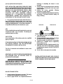
D. MODEL #CMB-31 ONLY: FAN INSTALLATION INSTRUCTIONS
This fireplace insert comes complete with a fan and temperature control switch assembly already installed. A speed control
/ receptacle assembly and (3) wire nuts are included in the fireplace components packet for wiring behind the lower air
passage. An electrical box and romex connector are pre-installed on a removable panel on the right side of the fireplace. If

Page 7
wiring to the pre-installed electrical box is desired, the wiring should be run prior to permanently setting the insert in place
and connecting the vent system.
NOTE: If this insert is being installed in the minimum opening dimensions, the wiring may need to be completed after the
fireplace insert is set in place.
The fan is equipped with a three-prong (grounding) plug attached to the end of the fan electrical cord for protection against
shock hazard and should be plugged directly into a properly grounded three-prong receptacle. Do not remove the grounding
prong from the plug. Do not allow any excess fan ford to touch the fireplace.
NOTE: Code approved line voltage wiring 14 gauge or better must be used when wiring this assembly. Refer to your local
electrical codes for specific requirements in your area.
WARNING: This appliance is equipped with a three-prong (grounding) plug for protection against shock hazard and should
be plugged directly into a properly grounded three-prong receptacle. Do not cut or remove the grounding
prong from this plug.
Figure D-1
INSTALLATION INSTRUCTIONS
1. Remove the (2) screws securing the removable access panel (with electrical box & romex connector installed) from the right
side of the fireplace.
2. Insert 115V wiring (with ground) through the romex connector and wire to the speed control / receptacle assembly matching
the black (hot) white (neutral) and green (ground) wire to the corresponding wire on the speed control / receptacle assembly.
NOTE: (3) wire nuts are included in the fireplace components packet.
3. Secure the speed control / receptacle assembly into the electrical box with the (2) screws provided.
This appliance, when installed, must be electrically grounded in accordance with local codes, or in the absence of local
codes, with the National Electrical Code, ANSI/NFPA 70, or the Canadian Electrical Codes, CSA C22.1.
MODEL #CMB-31-RF ONLY: FAN INSTALLATION INSTRUCTIONS
I
NSTALLATION OF THIS FAN WIRING SHOULD BE DONE ONLY BY A QUALIFIED INSTALLER
IMPORTANT: A fan assembly is pre-installed and wired to the RF gas valve in the CMB-31-RF models.

Page 8
An electrical box & romex connector are pre-installed on a removable panel on the right side of the fireplace.
A duplex receptacle and cover is included in the fireplace components packet. If wiring to the pre-installed
electrical box is desired, the wiring should be completed prior to permanently setting the insert in place and
connecting the vent system.
NOTE: If this insert is being installed in the minimum opening dimensions, the wiring may need to be
completed after the fireplace insert is set in place.
NOTE: Code approved line voltage wiring 14 gauge or better must be used when wiring this assembly. Refer to your
local electrical codes for specific requirements in your area.
WARNING: This appliance is equipped with a three-prong (grounding) plug for protection against shock hazard and should be
plugged directly into a properly grounded three-prong receptacle. Do not cut or remove the grounding prong from
this plug.
Figure D-2
1. Remove the (2) screws securing the removable access panel (with electrical box & romex connector installed) from the
right side of the fireplace.
2. Insert 115V wiring (with ground) through the romex connector and wire to the duplex receptacle. Secure the duplex
receptacle to the electrical box.
3. Place the cover on the electrical box and secure with screw.
This appliance, when installed, must be electrically grounded in accordance with local codes, or in the absence of local
codes, with the National Electrical Code, ANSI/NFPA 70, or the Canadian Electrical Codes, CSA C22.1.
E. INSTALLING THE INSERT
IMPORTANT: ALL STEPS IN SECTION ‘A) PREPARE THE EXISTING FIREPLACE’ MUST BE
COMPLETED BEFORE CONTINUING WITH THIS INSTALLATION.
1. INSTALL THE VENT SYSTEM

Page 9
TERMINATION CAP
INTAKE COLLAR
NOTE: Collar extends through the
bottom plate
Exhaust Collar
NOTE: Collar extends through the
middle divider plate
IMPORTANT:
INSTALL TERMINATION CAP WITH EXHAUST COLLAR
ON THE RIGHT SIDE. THE EXHAUST COLLAR ON
THE AIR DUCT FOR THE FIREPLACE IS ON THE RIGHT .
KOZY HEAT #816-CL CO-LINEAR VENT SYSTEM:
The co-linear pipe included in this vent system is designed to extend up to 30 ft.
IMPORTANT: The 3" exhaust pipe and exhaust collar on the termination cap can be identified by the label
attached to each end of the pipe and the label on the collar. It is imperative for proper operation
of this insert that the exhaust and combustion air pipes be connected to the correct collar on the
termination kit and air duct for the insert.
A. Carefully extend the 3” exhaust and combustion intake pipes to equal the total chimney
length required.
B. 1. Slide the 3" intake pipe (end without the collar) onto the collar on the termination cap and
secure with 3 self-tapping screws (provided).
2. Place a bead of sealant around the inner edge of the end of the 3" exhaust pipe (with
label) without the collar and slide onto the corresponding collar on the termination cap
(collar with label). Secure with 3 self-tapping screws (provided). Apply additional
sealant around the joint to ensure a seal.
FIGURE E-1
OTHER APPROVED 3" X 3" CO-LINEAR VENT SYSTEMS:
Dura-Vent, Ameri-Vent Direct, & Selkirk Metalbestos - Follow instructions included from the vent pipe
manufacturer as well as the venting installation requirements as outlined in this installation manual.
2. RUN THE VENT SYSTEM THROUGH THE EXISTING CHIMNEY
ˆ OPTIONAL: We recommend wrapping the first 3 ft. of the vent system below the termination cap with non-faced
fiberglass insulation (secure with wire) before running it through the existing chimney. This will prevent cold air
from coming down the existing chimney.
NOTE: If there are offsets in the existing chimney, it may be easier to place a weighted rope around the end of the
each 3" pipe to guide them through it.

Page 10
DO NOT ATTEMPT TO TIE ONE ROPE AROUND BOTH PIPES.
A. Guide the rope, if used, and flexible pipes down the existing
chimney. Figure E-2
B. To secure the chimney termination cap to the existing
chimney, apply a liberal bead of sealant (provided) around the
top of the existing chimney. Set the termination cap into
position as instructed in the vent system installation manual.
OPTIONAL: #816-CL kits - Secure the termination cap to the
existing chimney with the 2" self-tapping screws and anchor
straps provided. Screw holes are located at the sides of the
termination cap.
C. From inside the opening, grasp the ropes and CAREFULLY
pull the ropes until the 3” combustion air intake and 3” exhaust
pipes are down into the existing fireplace.
ˆ OPTIONAL: We recommend placing non-faced fiberglass
batting insulation between the pipes and existing chimney to
prevent heat loss up the chimney. (See Figure E-3)
Figure E-3
Figure E-2
OPTIONAL:
PLACE NON-FACED FIBERGLASS BATTING INSULATION
BETWEEN THE PIPES AND EXISTING CHIMNEY TO
PREVENT HEAT LOSS UP THE CHIMNEY.

Page 11
3. CONNECT THE VENT SYSTEM TO THE AIR DUCT
A. Place the air duct into the existing fireplace opening. Figure E-4
B. Place a bead of sealant (provided) around the 3” exhaust pipe (with label) and slide it inside the 3" collar
marked ‘Exhaust’ on the duct. Secure with (3) ½" self-tapping screws, provided. Apply additional
sealant around the joint to ensure an air tight seal. Figure E-5.
C. Apply a liberal bead of sealant (provided) around the 3” collar on the air duct. Slide the 3” combustion
intake pipe over the collar and secure with (3) ½" self-tapping screws, provided. To ensure an air-tight
seal, apply additional sealant around the joint. Figure E-5
.
Figure E-4
Figure E-5
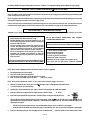
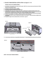
F. POSITION THE FIREPLACE INSERT:
1. #CMB-FLP Floor Protector Installation:
ZERO-CLEARANCE INSTALLATIONS: If you have removed the floor in the existing zero-clearance
fireplace, the #CMB-FLP floor protector must be installed over the exposed surface to protect to
combustible materials.
To install the #CMB-FLP floor protector:
A. Set the floor protector, insulation side down,
in desired position over the exposed
combustible material flooring.
Place the insert in the fireplace opening on
top of the #CMB-FLP floor protector.
IMPORTANT:
The #CMB-FLP and bottom of the fireplace insert
are the same size & shape. Make sure that the
insert is properly aligned onto the #CMB-FLP
floor protector.
Figure F-1
#CMB-FLP
Floor Protector
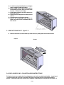
2. Slide the insert into the fireplace opening.
AIR DUCT

Page 12
CMB-FLP Floor Protector
Figure F-2
3. If using the CMB-FLP floor protector, make sure
that it is properly positioned under the insert.
Figure F-3
Figure F-3
4. Secure the air duct onto the insert by
positioning the air duct into the channels at
the top of the insert and sliding the air duct
forward until it stops. Figures F-4 & F-5
Figure F-4
Figure F-5
5. Secure the air duct to the insert, at the front,
with (2) ½" sheet metal screws (included in
the fireplace components packet). Refer to
Figure F-6.
Figure F-6
6. If necessary level the unit by threading the leveling bolts (included in the components packet) into
the nuts mounted in the bottom of the insert behind the lower air passage - 2 each side.
See Figure F-7.
Figure F-7
G. Complete the gas line installation:
Position air duct into the
channels and slide forward.

Page 13
1. This fireplace is designed to accept either a 3/8" or ½" gas line approved for gas appliances.
Consult local building codes to properly size the gas supply line leading to a 3/8" reduction.
2. Run the gas line into the fireplace, preferably through the left gas line hole. A gas line knock-out
is also located in the outer bottom of the insert when running the gas line through the bottom.
IMPORTANT: Do not run the incoming gas line in a manner that would obstruct the operation
of the fan.
3. Install the manual shut off valve (included with this fireplace) upstream from the regulator.
4. Connect the flexible gas line (installed on the gas valve on the millivolt board) to the manual shut
off valve.
H. Check millivolt board installation:
NOTE: Refer to pages #26 & #27 in this installation manual for complete millivolt board installation
procedures.
1. Ensure that all (6) nuts are attached to the mounting studs, securing the millivolt board in position .
2. Verify that the burner venturi is properly positioned over the burner orifice and the burner /cover
assembly is secured to the burner heat shield.
3. Check all gas connection for leaks, whether field or factory made.
I. Complete the fan wiring installation:
Model #CMB-31 only: Refer also to Figure C-1, page #7.

Page 14
1. Secure the electrical access panel to the side of the fireplace.
2. Place the thermostatic control switch on the bottom of the fireplace.
3. Plug the cord into the receptacle in the electrical box.
4. Turn the speed control counter-clockwise until it ‘clicks’. This is the ‘OFF’ position.
5. Turn the speed control ‘ON’ by turning the knob clockwise past the ‘click’ - this is the highest
setting.
Figure I-1
NOTE: The fan will not operate unless the speed control has been turned ‘ON’. The fan will not turn ‘ON’ until sufficient heat is
applied to the thermostatic control switch . The fan will turn ‘ON’ and ‘OFF’ automatically when the fireplace heats and cools.
Adjust fan to desired speed while it is running.
TEMPERATURE CONTROL SWITCH POSITION: Prior to adjusting the temperature control switch, unplug the 3-prong plug on the
fan cord from the receptacle. Adjust the position of the temperature control switch to a warmer location under the firebox to
turn the fan ‘ON’ sooner or move it to a cooler location under the firebox to turn the fan ‘ON’ later. The fan will turn on when the
sensor in the temperature control switch reaches 110
o
F and will turn ‘OFF’ when the sensors reach 90
o
F. After adjustment, plug
the 3-prong plug on the fan cord into the receptacle.
NOTE: This appliance must be electrically grounded and connected in accordance with local codes, or in the absence of local codes, with the National
Electrical Code, ANSI/NFPA 70-Current edition. or the Canadian Electrical Code, CSA C22.1.
Model #CMB-31-RF only: Refer also to Figure C-2 page #8.
1. Secure the electrical access panel to the side of the fireplace.
2. Plug the cord into the receptacle in the electrical box.
3. Upon complete installation of this fireplace, follow the lighting & shutdown instructions at the back
of this manual as well as the instructions included in the remote transmitter for complete fan
operation guidelines.
J) ATTACH THE SHROUD
Shroud assembly includes: (1) Shroud top (2) 10-24 x 1" RH Philips Mch Screw (#300388)
(1) Shroud left side (6) 8 x 3/8" Phillips PH-Type B Blk Zinc SMS (#300121)
(1) Shroud right side (4) 10-24 x 1/2" PH Phillips Truss head Screw BZ (300338-1)
Speed Control /
receptacle assembly
Thermostatic
Control Switch

Page 15
(1) Upper Hood
(1) Lower grill
ASSEMBLE THE SHROUD - Figure J-1
1. Attach the upper hood to the shroud top piece by
aligning the holes on the top flange on the hood to the
corresponding mounting holes on lower inside flange of
the shroud top piece. Secure with (2) 3/8" phillips head
screws (A), provided.
2. Secure the right and left shroud pieces to the top piece
by aligning the (2) holes in the side pieces to the holes in
the top piece. Secure with 3/8" phillips head screws
provided (2 ea. side) (B).
ATTACH THE SHROUD - Figure J-2
1. Align the slotted holes located on the inside flange of the
shroud side pieces to the threaded mounting nuts
located on the inside side flanges on the insert. NOTE:
There are (2) for each side.
2. Secure the shroud by inserting (1) 3/4" phillips head
screw through the slotted holes and into the threaded
mounting nuts. Do not tighten at this time.
3. Adjust shroud so that is sets against the fireplace face
finish material, then tighten the screws to secured in
position.
INSTALL THE LOWER GRILL - Figure J-2
1. Align the threaded mounting holes on each side of the
lower grill to the corresponding mounting holes on the
inside flange of the shroud side pieces and secure with
the (2) 1" phillips head screws, provided. (1 each side.)
Figure J-1
NOTE: Screws (A) & (B) are secured
from the bottom
.
Figure J-2 - Lower left side of insert and shroud shown.
Secure shroud with ½" phillips
head screws. (2) each side.
Secure lower grill with 1"
phillips head screw. (1 each side.)

Page 16
K. LOG INSTALLATION - Log Set #CMB-500
This log set includes 11 logs and 1 pkg. rock wool burning embers.
Note: Each log is numbered on the bottom and should be installed according to
the instructions and diagrams below.
1. Install base logs, C1, C2, C3, onto the burner as
shown in Figure K-1, aligning the mounting holes in
the bottom of the logs to the mounting studs in the
burner.
2. Install the ember logs, C4, C5 & C6 onto the front of
the burner as shown in Figure K-1.
3. Install middle log C7, and top logs C8, C9, C10, &
C11 onto the base logs as shown in Figure K-2
aligning the logs to the corresponding notched out
sections in the base logs.
C1
C2 C3
C5 C4 C6
Figure K-1
C8
C9
C10
C11 C7
Figure K-2
4. Place rock wool burning embers as desired onto the logs and burner to enhance glowing effect and flame
appearance.
NOTE: You will not use all the rock wool ember material at this time. Save
for future use.
Completed Log Set Installation
L. COMPLETE THE INSTALLATION

Page 17
1. THIS STEP SHOULD ONLY BE DONE BY A QUALIFIED INSTALLER OR SERVICE TECHNICIAN:
A) Perform lighting and shutdown procedures as described on pages #19-20. This should be done prior to replacing the
glass so that any necessary adjustments can be made and proper operation and log position verified.
2. REPLACE THE GLASS. Refer also to Figure L-1.
WARNING: DO NOT OPERATE THIS FIREPLACE
WITH THE GLASS ASSEMBLY REMOVED,
CRACKED, OR BROKEN. Replacement of the glass
assembly should be done by a licensed or qualified
service person.
A. Align the 2 slots in the top of the glass assembly over the 2
tabs on the fireplace (at the top).
B. Place the glass assembly so it is flush with the front of the
fireplace front.
C. While holding the glass assembly, pull the latches out and
secure over the glass latch clips on the bottom of the glass
frame locking it in place.
Figure L-1
Left intentionally blank.
M. MODEL CMB-31 ONLY: THERMOSTAT - WALL SWITCH - REMOTE INSTALLATION

Page 18
CAUTION: DO NOT CONNECT HIGH VOLTAGE (115V) WIRE TO THE GAS VALVE!
If
desired, a thermostat (wireless style available), wall switch,
or remote control assembly may be used to turn the fireplace
‘OFF’ and ‘ON’. Only ONE
of these may be installed. Follow
instructions included with each assembly.
OPTIONAL: Disconnect the on/off rocker switch wires from
the top & bottom terminals on the gas valve. Refer to Figure
Q-1, page #28 of this manual.
NOTE: INSTALLATION OF A THERMOSTAT OR WALL SWITCH
SHOULD ONLY BE DONE BY A QUALIFIED INSTALLER.
WALL SWITCH / THERMOSTAT USERS:
Run low-voltage (thermostat) wires from the terminals on the
gas valve to the desired location of the wall switch or
thermostat.
Attach the appropriate connector to each wall switch /
thermostat wire and connect to the top and bottom terminals
on the gas valve marked ‘TH’.
REMOTE CONTROL USERS:
Follow instructions included with the remote control.
IMPORTANT: The insulated cover included with the remote
control must be placed over the remote receiver to protect it
from overheating.
Remote Control Wiring Diagram
Figure M-2
Thermostat Wiring Diagram
Figure M-1
IMPORTANT: If the ON/OFF rocker switch wires are not
disconnected, the ON/OFF rocker switch on the millivolt board
must be in the ‘OFF’ position for proper operation of any of
these components.
If the rocker switch is ‘ON’, the fireplace burner will operate
until it is turned ‘OFF’ by the rocker switch. A wall switch,
thermostat, or remote control will not turn the fireplace ‘OFF’
when it has been turned ‘ON’ by the rocker switch.
NOTE: The fireplace must be turned ‘ON’ and ‘OFF’ by the
same method. For example: If the fireplace is turned ‘ON’ by
the remote control, it must be turned ‘OFF’ by the remote
control.
Page is loading ...
Page is loading ...
Page is loading ...
Page is loading ...
Page is loading ...
Page is loading ...
Page is loading ...
Page is loading ...
Page is loading ...
Page is loading ...
Page is loading ...
Page is loading ...
Page is loading ...
Page is loading ...
-
 1
1
-
 2
2
-
 3
3
-
 4
4
-
 5
5
-
 6
6
-
 7
7
-
 8
8
-
 9
9
-
 10
10
-
 11
11
-
 12
12
-
 13
13
-
 14
14
-
 15
15
-
 16
16
-
 17
17
-
 18
18
-
 19
19
-
 20
20
-
 21
21
-
 22
22
-
 23
23
-
 24
24
-
 25
25
-
 26
26
-
 27
27
-
 28
28
-
 29
29
-
 30
30
-
 31
31
-
 32
32
-
 33
33
-
 34
34


Ask a question and I''ll find the answer in the document
Finding information in a document is now easier with AI
Related papers
-
Kozyheat #911XXL Owner's manual
-
-
-
-
-
kozy heat #911XL Owner's manual
-
-
-
-
Other documents
-
FMI GWMT1 Operating instructions
-
 Tethys TT000059 User guide
-
 Purity UU000068 User guide
-
![XClearXClear Screen Protector for iPhone SE 2020 2nd Gen, iPhone 8, iPhone 7 (4.7-inch) (3 Pack), Tempered Glass Film + Alignment Tray Compatible iPhone SE 2nd Gen/ 8/7/ 6S/ 6 [Case Friendly]](//vs1.manuzoid.com/store/data/001208842_2-d48dd5c2b2285438ff05ee95d58681bf-160x210.png) XClear XClear Screen Protector for iPhone SE 2020 2nd Gen, iPhone 8, iPhone 7 (4.7-inch) (3 Pack), Tempered Glass Film + Alignment Tray Compatible iPhone SE 2nd Gen/ 8/7/ 6S/ 6 [Case Friendly] User guide
XClear XClear Screen Protector for iPhone SE 2020 2nd Gen, iPhone 8, iPhone 7 (4.7-inch) (3 Pack), Tempered Glass Film + Alignment Tray Compatible iPhone SE 2nd Gen/ 8/7/ 6S/ 6 [Case Friendly] User guide
-
Honeywell 396079 User manual
-
Superior SSBV-4035CNE User manual
-
Design House 753251 User manual
-
 Fluid Components International CMB User guide
-
Astria Fireplaces Sirius Instruction Sheet
-
 Trianium 4336690768 User manual


![XClearXClear Screen Protector for iPhone SE 2020 2nd Gen, iPhone 8, iPhone 7 (4.7-inch) (3 Pack), Tempered Glass Film + Alignment Tray Compatible iPhone SE 2nd Gen/ 8/7/ 6S/ 6 [Case Friendly]](http://vs1.manuzoid.com/store/data/001208842_2-d48dd5c2b2285438ff05ee95d58681bf-160x210.png)

