Page is loading ...

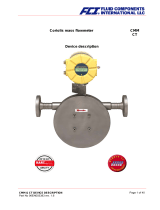
Coriolis mass flowmeter
CMB
CT
Device description
CMB & CT DEVICE DESCRIPTION
Part No 06EN003385 rev. 1.6 Page 1 of 38

1. IDENTIFICATION .................................................................................................. 5
2. THE CMB SENSOR............................................................................................... 6
2.1 Application domain of the CMB sensor ............................................................................................. 6
2.2 Mode of operation.............................................................................................................................. 6
2.2.1 Measuring principle .................................................................................................................... 6
2.2.2 System configuration .................................................................................................................. 6
2.2.3 Input............................................................................................................................................ 6
2.3 Custody transfer operations .............................................................................................................. 6
2.4 Performance characteristics of the CMB sensor ............................................................................... 7
2.4.1 Reference conditions.................................................................................................................. 7
2.4.2 CMB flow ranges ........................................................................................................................ 7
2.4.3 Density measurement................................................................................................................. 8
2.4.4 Accuracy ..................................................................................................................................... 8
2.4.5 Pressure loss CMB..................................................................................................................... 9
2.4.6 Ambient temperature .................................................................................................................. 9
2.4.7 Ambient temperature range........................................................................................................ 9
2.4.8 Storage temperature................................................................................................................... 9
2.4.9 Climatic category ........................................................................................................................ 9
2.4.10 Ingress protection ....................................................................................................................... 9
2.5 Operating conditions........................................................................................................................ 10
2.5.1 Installation................................................................................................................................. 10
2.5.2 Installation positions ................................................................................................................. 11
2.5.3 Assessment of installation position .......................................................................................... 12
2.5.4 Pressure surges ....................................................................................................................... 13
2.5.5 Using the device with hazardous fluids .................................................................................... 13
2.5.6 Vibration stability ...................................................................................................................... 13
2.6 Process conditions........................................................................................................................... 15
2.6.1 Process temperature ................................................................................................................ 15
2.6.2 Physical state ........................................................................................................................... 15
2.6.3 Viscosity.................................................................................................................................... 15
2.6.4 Gas content .............................................................................................................................. 15
2.6.5 Process temperature range...................................................................................................... 15
2.6.6 Process pressure range ........................................................................................................... 15
2.6.7 Outlet pressure ......................................................................................................................... 15
2.7 Connection to the transmitter .......................................................................................................... 15
2.7.1 Integral mount configuration..................................................................................................... 15
2.7.2 Remote mount configuration .................................................................................................... 15
2.8 Construction details ......................................................................................................................... 16
2.8.1 Dimensions and weight ............................................................................................................ 16
2.8.2 Dimension drawing for the types CMB-B to CMB-K................................................................. 17
2.8.2.1 Standard version dimension drawing................................................................................ 17
2.8.2.2 Integral mount version up to 150 °C (302 °F) ................................................................... 17
2.8.2.3 Remote mount version dimension drawing....................................................................... 18
2.8.2.4 Remote mount version dimension drawing up to 180 °C (356 °F) ................................... 18
Page 2 of 38 CMB & CT DEVICE DESCRIPTION

2.8.3 Heater dimension drawings for CMB-B up to CMB-K .............................................................. 19
2.8.3.1 Standard Heater for integral mount version CMB-B to CMB-K ........................................ 19
2.8.3.2 Heater for remote mount version CMB-B to CMB-K......................................................... 19
2.8.3.3 Heater for remote mount version up to 180 °C (356 °F)................................................... 20
2.8.4 Material..................................................................................................................................... 20
2.9 Sensor CMB approvals.................................................................................................................... 21
2.9.1 Explosion protection ................................................................................................................. 21
2.9.2 CE marking............................................................................................................................... 21
2.9.3 Custody transfer operations .....................................................................................................21
3. APPLICATION DOMAIN OF THE CT TRANSMITTER ........................................22
4. CT TRANSMITTER: MODE OF OPERATION AND CONFIGURATION ..............22
4.1 Measuring principle ......................................................................................................................... 22
4.2 System configuration ....................................................................................................................... 23
4.2.1 DSB data memory module ....................................................................................................... 23
5. INPUT...................................................................................................................24
5.1 Measured variable ........................................................................................................................... 24
5.2 Measuring range.............................................................................................................................. 24
6. OUTPUT...............................................................................................................25
6.1 Output signal.................................................................................................................................... 25
6.2 Failure signal ................................................................................................................................... 25
6.3 Load................................................................................................................................................. 26
6.4 Damping .......................................................................................................................................... 26
6.5 Low flow cutoff ................................................................................................................................. 26
7. CT PERFORMANCE CHARACTERISTICS .........................................................26
7.1 Reference conditions....................................................................................................................... 26
7.2 Measured error ................................................................................................................................ 26
7.3 Repeatability error ........................................................................................................................... 26
7.4 Influence of ambient temperature.................................................................................................... 26
8. CT OPERATING CONDITIONS ...........................................................................27
8.1 Installation conditions and cable glands.......................................................................................... 27
CMB & CT DEVICE DESCRIPTION
Part No 06EN003385 rev. 1.6 Page 3 of 38

8.2 Environmental conditions................................................................................................................. 27
8.2.1 Ambient temperature ................................................................................................................ 27
8.2.2 Ambient temperature range...................................................................................................... 27
8.2.3 Storage temperature................................................................................................................. 27
8.2.4 Ingress protection ..................................................................................................................... 27
8.3 Process conditions........................................................................................................................... 28
8.3.1 Fluid temperature ..................................................................................................................... 28
8.3.2 Physical state ........................................................................................................................... 28
8.3.3 Viscosity.................................................................................................................................... 28
8.3.4 Fluid temperature limit .............................................................................................................. 28
8.3.5 Flow rate limit ........................................................................................................................... 28
8.3.6 Pressure loss............................................................................................................................ 28
9. CONSTRUCTION DETAILS ................................................................................ 29
9.1 Type of construction/dimensions ..................................................................................................... 29
9.2 Weight.............................................................................................................................................. 30
9.3 Material ............................................................................................................................................ 30
9.4 End connection ................................................................................................................................ 30
9.5 Electrical connection........................................................................................................................ 31
9.5.1 CT connections......................................................................................................................... 31
9.5.2 Wiring diagram ......................................................................................................................... 33
9.5.2.1 Wiring diagram for the integral mount configuration of sensor and CT ............................ 33
9.5.2.2 Wiring diagram for the remote mount configuration of sensor and CT............................. 34
9.5.3 HART®...................................................................................................................................... 35
9.5.4 Communication via SensorPort................................................................................................ 35
10. CONTROL UNIT BE2 .......................................................................................... 36
10.1 Introduction .................................................................................................................................. 36
10.2 Display.......................................................................................................................................... 36
11. CERTIFICATES AND APPROVALS.................................................................... 37
12. STANDARDS AND AUTHORIZATIONS.............................................................. 37
12.1 General standards and directives ................................................................................................37
12.2 Electromagnetic compatibility ...................................................................................................... 37
12.3 Ex-Approval transmitter................................................................................................................ 37
Page 4 of 38 CMB & CT DEVICE DESCRIPTION

1. Identification
Manufacturer FCI Fluid Components International LLC
1755 La Costa Meadows Drive
San Marcos, CA 92078
Phone: 760 – 744 – 6950
Fax: 760 – 736 – 6250
Internet: http://www.fluidcomponents.com
E-mail: mailto:[email protected]
European Office:
Persephonestraat 3-01
5047 TT Tilburg
Netherlands
Phone: +31 – 13 – 515 9989
Fax: +31 – 13 – 579 9036
Product type Mass flowmeter for liquid and gaseous products
Product name Sensor type CMB
Transmitter type CT, suitable for CMM, CMB and CMU Coriolis mass flow-
meters
Version no. 1.6, dated April 10, 2006
CMB & CT DEVICE DESCRIPTION
Part No 06EN003385 rev. 1.6 Page 5 of 38

2. The CMB sensor
2.1 Application domain of the CMB sensor
The sensor is intended for use solely for direct and continuous mass flow measurement of liquids and
gases, irrespective of their conductivity, density, temperature, pressure, or viscosity. The sensor is also
intended for use for the direct and continuous mass flow measurement of chemical fluids, suspensions,
molasses, paint, varnish, lacquer, pastes and similar materials.
[
]
vmFC
×
⋅
⋅
=
ω
2
2.2 Mode of operation
2.2.1 Measuring principle
The Coriolis mass flowmeter is based on the
principle whereby in a rotating system a force
(known as the Coriolis force) is exerted on a
mass at a rotation point that is moving towards
or away from this point.
2.2.2 System configuration
The flowmeter consists of a sensor that is mounted in a pipe, and a transmitter (see Section 3
Application domain of the CT on pp. 22), that can be directly mounted on the sensor or installed sepa-
rately (e.g. on a wall).
The transmitter oscillates the flow tubes in the sensor over an excitation coil and picks up, via the sensor
coil, the measuring signal which is proportional to the mass flow. After being temperature compensated,
the measuring signal is converted into an analog output signal that is consistent with the measuring range
setting.
2.2.3 Input
Measured variables: mass flow, density, temperature; volume flow is calculated
2.3 Custody transfer operations
Units designated for custody transfer operation may be certified in accordance to the local or national
ordinance. Transmitters ordered for custody transfer applications incorporate special tamper-proof soft-
ware, sealed and certified, that prevents the reset of the internal totalizer.
Page 6 of 38 CMB & CT DEVICE DESCRIPTION

2.4 Performance characteristics of the CMB sensor
2.4.1 Reference conditions
• Established flow profile
• Inlet section has to correspond to mounting length
• Operation is to be realized in the presence of downstream control valves
• Measurement is to be realized in the absence of any gas bubbles
• Flow tubes are to be kept clean at all times
• Process temperature is to be regulated as specified in Section 2.6.1 Process temperature on
page 15
• Process pressure is to be regulated as specified in Section 2.6.6 Process pressure range on
page 15
• Ambient temperature is to range from + 10 °C to + 30 °C (50 °F to 86 °F)
• Warm-up period: 15 minutes
• Standard calibration is to be realized at 20 %, 50 % and 100 % (three times each)
• High-frequency interference is to be regulated as specified in Section 12.2 Electromagnetic
compatibility on page 37
2.4.2 CMB flow ranges
Model kg/h [lbs/min] kg/h [lbs/min] kg/h [lbs/min] kg/h [lbs/min]
CMB-B 20 [0.7] 200 [7.3] 96 [3.5] 0.02 [0.001]
CMB-C 35 [1.3] 350 [12.9] 282 [10.4] 0.035 [0.00]
CMB-D 120 [4.4] 1,200 [44.1] 1,030 [37.8] 0.12 [0.00]
CMB-E 300 [11.0] 3,000 [110.2] 3,000 [110.2] 0.3 [0.0]
CMB-F 600 [22.0] 6,000 [220.5] 5,750 [211.3] 0.6 [0.0]
CMB-G 2,000 [73.5] 20,000 [734.9] 13,000 [477.7] 2 [0.1]
CMB-J 4,000 [147.0] 40,000 [1,469.7] 34,000 [1,249.3] 4 [0.1]
CMB-K 6,000 [220.5] 60,000 [2,204.6] 57,000 [2,094.4] 6 [0.2]
Zero point stability
(of range)
Max.
measuring range
Nominal
(p=1bar)
Min.
measuring range
Reference conditions: in conformity with IEC 770:
Temperature: 20 °C, relative humidity: 65 %, air pressure: 101.3 kPa
Fluid: water
CMB & CT DEVICE DESCRIPTION
Part No 06EN003385 rev. 1.6 Page 7 of 38

2.4.3 Density measurement
The attainable accuracy depends on the selected calibration type.
Without calibration no density measurement is possible and the empty pipe recognition
is not available!
Model without 3-Point 5-Point
CMB-B
CMB-C
CMB-D 5 g/l 3 g/l
CMB-E 5 g/l 3 g/l
CMB-F 5 g/l 3 g/l
CMB-G 5 g/l 3 g/l
CMB-J 5 g/l 3 g/l
CMB-K 5 g/l 3 g/l
Density accuracy
not available
no measurement of density
2.4.4 Accuracy
Mass flow
Accuracy CMB-B to CMB-K ± 0.15% of actual flow + zero point stability (see Section 2.4.2 CMB
flow ranges)
Repeatability error ± 0.05% of actual flow (sensor with transmitter)
Additional measured values
Volume flow ± 0.2 % of actual value + zero point stability
Temperature ± 0.5 °C
Hysteresis n/a
Settling time 1 to 15 seconds
Startup drift 15 minutes
Long-term drift ± 0.02 % of upper-range value per year
Influence of ambient temperature ± 0.005 % per K
Influence of fluid temperature Compensated
Influence of fluid pressure For fluids: too small to be relevant
Page 8 of 38 CMB & CT DEVICE DESCRIPTION

2.4.5 Pressure loss CMB
Model Min.
measuring range Max.
measuring range
20 kg/h 50 kg/h 100 kg/h 150 kg/h 200 kg/h
0.06 bar 0.32 bar 1.08 bar 2.20 bar 3.64 bar
35 kg/h 113.75 kg/h 192.5 kg/h 271.25 kg/h 350 kg/h
0.03 bar 0.21 bar 0.52 bar 0.94 bar 1.47 bar
120 kg/h 390 kg/h 660 kg/h 930 kg/h 1200 kg/h
0.02 bar 0.19 bar 0.47 bar 0.85 bar 1.34 bar
300 kg/h 975 kg/h 1650 kg/h 2325 kg/h 3000 kg/h
0.01 bar 0.08 bar 0.19 bar 0.35 bar 0.55 bar
600 kg/h 1950 kg/h 3300 kg/h 4650 kg/h 6000 kg/h
0.02 bar 0.15 bar 0.38 bar 0.69 bar 1.08 bar
2000 kg/h 6500 kg/h 11000 kg/h 15500 kg/h 20000 kg/h
0.04 bar 0.30 bar 0.76 bar 1.38 bar 2.16 bar
4000 kg/h 13000 kg/h 22000 kg/h 31000 kg/h 40000 kg/h
0.02 bar 0.19 bar 0.46 bar 0.85 bar 1.32 bar
6000 kg/h 19500 kg/h 33000 kg/h 46500 kg/h 60000 kg/h
0.02 bar 0.15 bar 0.38 bar 0.70 bar 1.09 bar
Model Min.
measuring range Max.
measuring range
0.73 lbs/min 1.84 lbs/min 3.67 lbs/min 5.51 lbs/min 7.3 lbs/min
0.94 psi 4.66 psi 15.69 psi 31.90 psi 52.77 psi
1.29 lbs/min 4.18 lbs/min 7.07 lbs/min 9.97 lbs/min 12.9 lbs/min
0.38 psi 2.99 psi 7.51 psi 13.68 psi 21.37 psi
4.4 lbs/min 14.3 lbs/min 24.3 lbs/min 34.2 lbs/min 44.1 lbs/min
0.34 psi 2.71 psi 6.80 psi 12.40 psi 19.37 psi
11.0 lbs/min 35.8 lbs/min 60.6 lbs/min 85.4 lbs/min 110.2 lbs/min
0.14 psi 1.12 psi 2.81 psi 5.13 psi 8.01 psi
22.0 lbs/min 71.6 lbs/min 121.3 lbs/min 170.9 lbs/min 220.5 lbs/min
0.28 psi 2.19 psi 5.50 psi 10.02 psi 15.65 psi
73.5 lbs/min 238.8 lbs/min 404.2 lbs/min 569.5 lbs/min 734.9 lbs/min
0.56 psi 4.37 psi 10.98 psi 20.01 psi 31.26 psi
147.0 lbs/min 477.7 lbs/min 808.3 lbs/min 1139.0 lbs/min 1469.7 lbs/min
0.34 psi 2.69 psi 6.74 psi 12.29 psi 19.20 psi
220.5 lbs/min 716.5 lbs/min 1212.5 lbs/min 1708.6 lbs/min 2204.6 lbs/min
0.28 psi 2.21 psi 5.55 psi 10.11 psi 15.79 psi
220.5 lbs/min
CMB-J 147.0 lbs/min 1,469.7 lbs/min
734.9 lbs/minCMB-G 73.5 lbs/min
CMB-F 22.0 lbs/min
CMB-B 0.73 lbs/min
CMB-C 1.29 lbs/min
CMB-E 11.0 lbs/min
Pressure loss [water (20°C), 1 mPas]
Pressure loss [water (20°C), 1 mPas]
7.3 lbs/min
12.9 lbs/min
40000 kg/h
6000 kg/h
20000 kg/h
CMB-J 4000 kg/h
CMB-F 600 kg/h
CMB-G 2000 kg/h
3000 kg/hCMB-E 300 kg/h
1200 kg/hCMB-D 120 kg/h
CMB-B 20 kg/h 200 kg/h
350 kg/hCMB-C 35 kg/h
CMB-K 6000 kg/h 60000 kg/h
CMB-K 220.5 lbs/min 2,204.6 lbs/min
44.1 lbs/minCMB-D 4.4 lbs/min
110.2 lbs/min
2.4.6 Ambient temperature
− 40 °C to + 60 °C (-40 °F to 140 °F)
2.4.7 Ambient temperature range
− 40 °C to + 60 °C (-40 °F to 140 °F); a special cable is required for temperatures below − 20 °C (-4 °F)
2.4.8 Storage temperature
− 25 °C to + 60 °C (-13 °F to 140 °F), − 40 °C (-40°F) available as special version
2.4.9 Climatic category
In conformity with IEC 654-1. Unsheltered class D locations with direct open-air climate.
2.4.10 Ingress protection
Standard version: IP 66 (NEMA 6); special version IP 68 (NEMA 6P) DIN EN 60529, if suitable and tightly
screwed down cable glands are used.
CMB & CT DEVICE DESCRIPTION
Part No 06EN003385 rev. 1.6 Page 9 of 38

2.5 Operating conditions
2.5.1 Installation
The sensor is to be protected, wherever possible, against valves, manifolds and similar fittings that gen-
erate turbulence. The sensor is to be installed in accordance with the following instructions.
Diagram showing flowmeter installation
A
BC C C
C
Flowmeter installation: A = sensor, B = valve, C = pipe clamps and supports
Under no circumstances is the
sensor to be used to support a
pipe.
Do not install the sensor in sus-
pended pipes.
Do not adjust the position of a
pipe by pulling or grasping the
sensor.
Page 10 of 38 CMB & CT DEVICE DESCRIPTION

2.5.2 Installation positions
Standard installation position
Installation position A
Installation position B
Installation position C
CMB & CT DEVICE DESCRIPTION
Part No 06EN003385 rev. 1.6 Page 11 of 38

2.5.3 Assessment of installation position
Type of fluid Position Assessment
Pure liquids Standard installation
position
Self-draining flow tubes
Position A or B OK
Position C Liquid residue remains in pipe
Liquids with gas bub-
bles
Standard installation
position
Self-draining flow tubes, gas bubbles do not accumulate
in flowmeter
Position A Not recommended owing to gas bubble accumulation in
flowmeter
Position B Gas bubbles may accumulate in the presence of low flow
velocities
Position C No gas bubble accumulation in flowmeter, liquid residues
may remain in device after discharge
Liquids containing
substances that could
form deposits
Standard installation
position
Self-draining flow tubes, no deposit formation
Position A OK
Position B Substances in the liquid could form deposits at low flow
velocities
Position C Not recommended owing to presence in flowmeter of
substances that could form deposits
Liquids containing
gas bubbles, as well
as gas bubbles con-
taining substances
that could form de-
posits
Standard installation
position
Self-draining flow tubes, no accumulation of gases or
substances that could form deposits
Position A Not recommended owing to gas bubble accumulation in
flowmeter
Position B Gas bubbles or substances that could form deposits at
low flow velocities
Position C Not recommended owing to presence in flowmeter of
substances that could form deposits
Gases that do not
form a condensate
Standard installation
position,
Position A, B or C
Any of these installations positions can be used
Gas, condensate-
forming gas/liquid,
moisture
Standard installation
position
Flow direction should be from top to bottom so that any
condensate that forms can flow out efficiently
Position A OK
Position B Condensate might form in flowmeter
Position C Not recommended owing to condensate accumulation in
flowmeter
Page 12 of 38 CMB & CT DEVICE DESCRIPTION

Type of fluid Position Assessment
Slurries Standard installation
position
Optimal installation position
Position A High density substances could accumulate in the flow-
meter
Position B Gas bubbles could accumulate
Position C Gas bubbles or high density substances could accumu-
late in the flowmeter
2.5.4 Pressure surges
Pressure surges in a pipe could be provoked by a sudden decrease in flow caused by rapid closing of a
valve or similar factors. This change in pressure can lead to underpressure downstream from a valve that
has been closed rapidly, and to outgasing. If the valve is mounted directly on the inlet section of the
flowmeter, a gas bubble can form in the flow tube that can cause a measuring signal disturbance that
would shift the zero point of the output signal. In extreme cases, a pressure surge could cause mechani-
cal damage to the sensors and/or flow tube.
Whenever possible, quick-closing valves should be mounted downstream from the sensor. If this is not
feasible, such valves are to be mounted a minimum of 10 x DIA (Φ) from the nearest sensor. Alterna-
tively, valve closing speed can be reduced.
2.5.5 Using the device with hazardous fluids
The sealing technology used in the standard mass flowmeter renders the device unsuitable for use with
hazardous fluids. Only sensors that meet the standards for safety instruments are suitable for use with
hazardous fluids.
The pathway between the sensor and transmitter must be pressure-tight so as to prevent fluid from leak-
ing out of a sensor in the event a sensor develops a defect.
In the case of welded components, a colored liquid penetration test should be performed on the welds, or
one joint (only the first one) should be x-rayed. Alternatively, an internal pressure monitoring device can
be used to detect any defect.
2.5.6 Vibration stability
The sensors are insensitive to vibration; vibration stability has been validated in accordance with
DIN IEC 68-2-6, for up to 1 g at 10 to 150 Hz.
If pipe vibration is greater than 1 g in the 10-150 Hz range, an additional fastening is to be mounted as
shown in the following drawings. This fastening will prevent vibration from affecting the device’s mechani-
cal configuration and/or measurement readings. The following drawings are valid for a sensor with a
nominal size of approximately 2 inches [DN 040]. Installation is to be realized as shown in this drawing.
CMB & CT DEVICE DESCRIPTION
Part No 06EN003385 rev. 1.6 Page 13 of 38

Installation using wall supports
Foot-mounted installation
Page 14 of 38 CMB & CT DEVICE DESCRIPTION

2.6 Process conditions
2.6.1 Process temperature
− 40 °C to + 180 °C (-40 °F to 356 °F); rating plate range must be observed
2.6.2 Physical state
Liquid product (maximum density 2 kg/l)
Gaseous product (minimum density 0.002 kg/l in operating state)
2.6.3 Viscosity
0.3 up to 50,000 mPas (0.3 to 50,000 cP)
2.6.4 Gas content
The use of products containing gas is not allowed for custody transfer operations. In other applications,
the presence of gas will increase false readings. In order for the readings of products containing gas to
be valid, small gas bubbles must be homogeneously distributed in the fluid. Large gas bubbles will auto-
matically provoke extremely false readings and will shift the zero point. Thus, the extent to which readings
are false is determined by the process conditions. A rule of thumb in this regard is as follows: A 1 % gas
component will increase false readings by 1 %. The gas component is not to exceed 5 %.
2.6.5 Process temperature range
+ 180 °C (356 °F)
2.6.6 Process pressure range
According to PN16 pressure rating: 232 psig [16 bar] and PN40: 580 psig [40 bar]
2.6.7 Outlet pressure
Outlet pressure must be greater than the vapor pressure Ps (static pressure) of the measured product.
2.7 Connection to the transmitter
2.7.1 Integral mount configuration
When the transmitter is mounted directly on the sensor, no cable connection between the two compo-
nents is needed. This connection is integrated at the factory.
2.7.2 Remote mount configuration
If the transmitter is not mounted directly on the sensor, installation regulations and applicable legal stan-
dards are to be adhered to. The maximum cable length is 300 m (1000ft). See Section 9.5.2 Wiring dia-
gram on page 33 for information regarding the connection and cable specifications.
CMB & CT DEVICE DESCRIPTION
Part No 06EN003385 rev. 1.6 Page 15 of 38

2.8 Construction details
2.8.1 Dimensions and weight
Standard versions:
Model Endconnection inch [mm] inch [mm] inch [mm] inch [mm] inch [mm] inch [mm]
CMB-B DN10 PN40, ANSI ½" 150/300lb 11.8 [300] 14.3 [363] 18.3 [465] 10.4 [265] 14.4 [367] 4.4 [113]
CMB-C DN10 PN40, ANSI ½" 150/300lb 11.8 [300] 14.3 [363] 18.3 [465] 10.4 [265] 14.4 [367] 4.4 [113]
CMB-D DN15 PN40, ANSI ¾" 150/300lb 11.8 [300] 14.3 [363] 18.3 [465] 10.4 [265] 14.4 [367] 4.4 [113]
CMB-E DN25 PN40, ANSI 1" 150/300lb 15.7 [400] 16.9 [430] 20.9 [532] 13.1 [332] 17.1 [434] 6.8 [173]
CMB-F DN25 PN40, ANSI 1" 150/300lb 15.7 [400] 16.9 [430] 20.9 [532] 13.1 [332] 17.1 [434] 6.8 [173]
CMB-G DN50 PN40, ANSI 2" 150/300lb 19.7 [500] 18.5 [471] 22.6 [573] 14.7 [373] 18.7 [475] 8.1 [206]
CMB-J DN80 PN40, ANSI 3" 150/300lb 23.6 [600] 21.9 [557] 25.9 [659] 18.1 [459] 22.1 [561] 11.4 [290]
CMB-K DN80 PN40, ANSI 3" 150/300lb 23.6 [600] 21.9 [557] 25.9 [659] 18.1 [459] 22.1 [561] 11.4 [290]
A
Integral Mount Transmitter Remote Mount Transmitter
B
-40°C - 100°C
(-40°F to 212°F)
-40°C - 150°C
(-40°F to 302°F)
-40°C - 100°C
(-40°F to 212°F)
-40°C - 180°C
(-40°F to 356°F)
C
Weight:
Model DN kg [lbs] kg [lbs]
CMB-B 10 13 [28.7]
CMB-C 10 13 [28.7]
CMB-D 15 13 [28.7]
CMB-E 25 20 [44.1] 4.5 [9.9]
CMB-F 25 20 [44.1]
CMB-G 50 27 [59.5]
CMB-J 80 50 [110.2]
CMB-K 80 50 [110.2]
Sensor Transmitter
Weight
Heated versions:
Model inch [mm] inch [mm] inch [mm]
CMB-B 5.4 [138] 8.5 [215] 0.8 [20]
CMB-C 5.4 [138] 8.5 [215] 0.8 [20]
CMB-D 5.4 [138] 8.5 [215] 0.8 [20]
CMB-E 5.4 [138] 11.0 [280] 1.2 [30.5]
CMB-F 5.4 [138] 11.0 [280] 1.2 [30.5]
CMB-G 8.5 [216] 12.0 [306] 1.2 [30.5]
CMB-J 8.5 [216] 15.9 [403] 1.7 [43]
CMB-K 8.5 [216] 15.9 [403] 1.7 [43]
KLM
Page 16 of 38 CMB & CT DEVICE DESCRIPTION

2.8.2 Dimension drawing for the types CMB-B to CMB-K
2.8.2.1 Standard version dimension drawing
Integral mount configuration that is suitable for process temperatures up to 100 °C (212°F):
For all the dimensions and weight, see Section 2.8.1 Dimensions and weight on page 16.
2.8.2.2 Integral mount version up to 150 °C (302 °F)
Integral mount configuration that is suitable for process temperatures up to 150 °C (302°F):
For all the dimensions and weights, see Section 2.8.1 Dimensions and weight on page 16.
CMB & CT DEVICE DESCRIPTION
Part No 06EN003385 rev. 1.6 Page 17 of 38

2.8.2.3 Remote mount version dimension drawing
Remote mount configuration with junction box that is suitable for process temperatures up to 100 °C
(212 °F):
For all the dimensions and weights, see Section 2.8.1 Dimensions and weight on page 16.
2.8.2.4 Remote mount version dimension drawing up to 180 °C (356 °F)
Remote mount configuration with junction box that is suitable for process temperatures up to 180 °C
(356 °F):
For all the dimensions and weights, see Section 2.8.1 Dimensions and weight on page 16.
Page 18 of 38 CMB & CT DEVICE DESCRIPTION

2.8.3 Heater dimension drawings for CMB-B up to CMB-K
2.8.3.1 Standard Heater for integral mount version CMB-B to CMB-K
Integral mount configuration that is suitable for process temperatures up to 100 °C (212 °F):
For all the dimensions and weights, see Section 2.8.1 Dimensions and weight on page 16.
2.8.3.2 Heater for remote mount version CMB-B to CMB-K
Remote mount configuration (with junction box) that is suitable for process temperatures up to 100 °C
(212 °F):
CMB & CT DEVICE DESCRIPTION
Part No 06EN003385 rev. 1.6 Page 19 of 38

For the dimensions and weights, see Section 2.8.1 Dimensions and weight on page 16.
2.8.3.3 Heater for remote mount version up to 180 °C (356 °F)
Remote mount configuration (with junction box) that is suitable for process temperatures up to 180 °C
(356 °F):
For the dimensions and weights, see Section 2.8.1 Dimensions and weight on page 16.
2.8.4 Material
Sensor housing
CMB up to 3 inch [DN080]: GGG 40.3 with stainless steel 1.4301 (304L) cover plate and
plastic cover (max. 100 °C / 212 °F environment temperature)
Flow tubes:
Splitter:
Sealing strip
Flange:
1.4404 (316L)
1.4571 (316Ti)
1.4404 (316L)
GGG 40.3
Page 20 of 38 CMB & CT DEVICE DESCRIPTION
/