Page is loading ...

EXPRESSBOX 3400
User Manual
PCIe to PCIe Expansion
Model
EB3400

Magma
ExpressBox 3400 |
2
Table of Contents
Preface ..................................................................................................................................4
Advisories ............................................................................................................................ 4
Safety Instructions ................................................................................................................ 5
Chapter 1 ExpressBox 3400 Expansion ..............................................................................7
ExpressBox 3400 PCI Express Specifications ......................................................................... 8
Pre-Installation Information .................................................................................................... 9
ExpressBox 3400 (7 Slot Expansion – Gen3) ............................................................................ 9
Components of ExpressBox 3400 .......................................................................................... 10
Tools Required for Installation .............................................................................................. 12
Chapter 2 Hardware Installation .....................................................................................12
Installation-Procedures Overview .......................................................................................... 13
Open Enclosure (STEP 1) .................................................................................................... 13
Install Expansion Interface card (STEP 2) ............................................................................... 14
Install Host Interface card (STEP 3) ....................................................................................... 15
Install PCIe Cards (STEP 4) .................................................................................................. 16
Aux Power Connectors ...................................................................................................... 17
High Power PCIe card installation ....................................................................................... 17
Connect PCIe Cable (STEP 5) ................................................................................................ 19
To Disconnect Cable ......................................................................................................... 19
Cable Configuration .......................................................................................................... 20
Attach Power Cord (STEP 6) ................................................................................................. 20
Connect to Electrical Outlet (STEP 7) .................................................................................... 21
Turn ON Expansion Unit (STEP 8) .......................................................................................... 21
Power ON the Computer (STEP 9) ........................................................................................ 22
Hardware Check (STEP 10)................................................................................................... 22
Check and verify Backplane LEDs ....................................................................................... 22
Check and verify Expansion Card LEDs ............................................................................... 22
Check and verify Host Card LEDs ....................................................................................... 23
Chapter 3 Software Installation ......................................................................................24
Software Check - Verify Installation (STEP 11) ........................................................................ 24
Check Magma Device - Windows 7 and 8 ............................................................................ 24
To check the Magma Device ID .......................................................................................... 24
Check Magma device - Mac OS X ....................................................................................... 25
Check Magma device – Linux ............................................................................................ 26
How To Check PCIe cards - Mac OS X .................................................................................... 26

Magma
ExpressBox 3400 |
3
How To Check PCIe cards - Windows 7 and 8 ......................................................................... 27
Chapter 4 Advanced Technical Information .....................................................................28
Interface Card LEDs ............................................................................................................ 28
LINKUP & SLOT LEDs ........................................................................................................... 30
Activity LEDs ...................................................................................................................... 31
Backplane LEDs ................................................................................................................. 31
Internal Front Fan (Control Settings) ..................................................................................... 32
Front Fan Removal / Installation ........................................................................................... 33
Chapter 5 Troubleshooting ................................................................................................34
Chapter 6 How to Get More Help ........................................................................................36
Contacting Technical Support ............................................................................................... 36
Returning Merchandise to MAGMA ......................................................................................... 36

Magma
ExpressBox 3400 | Preface
4
Preface
Advisories
Five types of advisories are used throughout this manual to provide helpful information, or to alert you to
the potential for hardware damage or personal injury.
NOTE
Used to amplify or explain a comment related to procedural steps or text.
IMPORTANT
Used to indicate an important piece of information or special “tip” to help you
CAUTION
Used to indicate and prevent the following procedure or step from causing damage to the
equipment.
WARNING
Used to indicate and prevent the following step from causing injury.
DANGER or STOP
Used to indicate and prevent the following step from causing serious injury or significant
data loss
Disclaimer: We have attempted to identify most situations that may pose a danger, warning, or caution
condition in this manual. However, Magma does not claim to have covered all situations that might require
the use of a Caution, Warning, or Danger indicator.

Magma
ExpressBox 3400 | Preface
5
Safety Instructions
Always use caution when servicing any electrical component. Before handling the Magma Expansion
chassis, read the following instructions and safety guidelines to prevent damage to the product and to
ensure your own personal safety. Refer to the “Advisories” section for advisory conventions used in this
manual, including the distinction between Danger, Warning, Caution, Important, and Note.
§ Always use caution when handling/operating the computer. Only qualified, experienced,
authorized electronics personnel should access the interior of the computer and expansion
chassis.
WARNING
Never modify or remove the radio frequency interference shielding from your workstation or
expansion unit. To do so may cause your installation to produce emissions that could
interfere with other electronic equipment in the area of your system.
When Working Inside a Computer
1. Before taking covers off a computer, perform the following steps:
2. Turn off the computer and any peripheral devices.
3. Disconnect the computer and peripheral power cords from their AC outlets or inlets in order to
prevent electric shock or system board damage.
In addition, take note of these safety guidelines when appropriate:
§ To help avoid possible damage to systems boards, wait five seconds after turning off the computer
before removing a component, removing a system board, or disconnecting a peripheral device
from the computer.
§ When you disconnect a cable, pull on its connector or on its strain-relief loop, not on the cable
itself. Some cables have a connector with locking tabs. If you are disconnecting this type of cable,
press in on the locking tabs before disconnecting the cable. As you pull connectors apart, keep
them evenly aligned to avoid bending any connector pins. Also, before connecting a cable,
make sure both connectors are correctly oriented and aligned.
CAUTION
Do not attempt to service the system yourself except as explained in this manual. Follow
installation instructions closely.

Magma
ExpressBox 3400 | Preface
6
Protecting Against Electrostatic Discharge
Electrostatic Discharge (ESD) Warning
Electrostatic Discharge (ESD) is the enemy of semiconductor devices. You should always
take precautions to eliminate any electrostatic charge from your body and clothing before
touching any semiconductor device or card by using an electrostatic wrist strap and/or
rubber mat.
Static electricity can harm system boards. Perform service at an ESD workstation and follow proper ESD
procedures to reduce the risk of damage to components. Magma strongly encourages you to follow
proper ESD procedures, which can include wrist straps and smocks, when servicing equipment.
You can also take the following steps to prevent damage from electrostatic discharge (ESD):
• When unpacking a static-sensitive component from its shipping carton, do not remove the
component’s anti-static packaging material until you are ready to install the component in a
computer. Just before unwrapping the anti-static packaging, be sure you are at an ESD
workstation or are grounded.
• When transporting a sensitive component, first place it in an anti-static container or packaging.
• Handle all sensitive components at an ESD workstation. If possible, use anti-static floor pads and
workbench pads.
• Handle components and boards with care. Don’t touch the components or contacts on a board.
Hold a board by its edges or by its metal mounting bracket.

Magma
ExpressBox 3400 | Chapter 1 ExpressBox 3400 Expansion
7
Chapter 1 ExpressBox 3400 Expansion
Precision engineered to Magma’s mission critical standards for performance and reliability, ExpressBox
3400 features seven (7) full-length, full-height PCIe slots and PCIe Gen 3 expansion board. Designed with
your work station in mind, the EB3400 has a 540-watt power supply, auxiliary power, and features Magma’s
exclusive quiet cooling control.
The ExpressBox 3400 Expansion is compatible with a series of operating systems including MacOS, Windows,
Linux, and Solaris.
• Seven (7) available full length/full height PCIe expansion slots
• Tool-less cover removal
• White power-on indicator front panel light
• Two 92 x 92 x 25 mm Fans
• Adjustable fan control option (or full speed)
• Speeds up to 8 GT/s (PCIe x8 Gen 3)
• Connect PCI Express Host to Expansion over cable
• Use same PCIe interface card for both sides of the connection
• High Speed IO cable
EXPRESSBOX 3400 PCI Express
Product Name Description
ExpressBox 3400 7 Slot – Expansion Gen 3
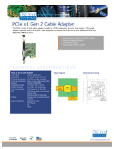
Use Magma’s PCI Express Expansion to create a super-fast PCIe connection outside the computer
The ExpressBox 3400 is the perfect solution for creating a super-fast local PCIe connection from a host
computer to a target PCI Express device. The Magma 01-08003-00 interface card installs into any x8 or x16
PCIe slot in the host computer motherboard and the other Magma 01-08003-00 interface card is inserted
into a designated upstream PCIe slot. A high-speed IO cable allows data transfers to and from the host
computer at 64 Gbps (8 Gb/s per lane multiply by 8 lanes).
Features:
• High-speed x8 PCI Express connection
• Easy Plug and Play installation
• Low profile bracket provides for easy installation in low profile computers
• Easily visible LEDs that indicate correct installation and PCIe link width
• Low power consumption - less than 4 Watts
• LEDs show status of connection for quick debug- reset indicator, clock indicator, link width
indicator
• Supports Spread Spectrum Clocking, LOS (Loss of Signal), LOL (Loss of Lock Indicator)
• Low Latency and Low Jitter
• 540 Watt Power Supply
• Auxiliary Power Cable

Magma
ExpressBox 3400 | Chapter 1 ExpressBox 3400 Expansion
8
Benefits:
• Attach PCIe Cards to any Computers
• Transparent extension of PCI Express signals outside the computer
• No software required - connection is automatically recognized and configured by system BIOS
• Attach large power hungry PCI Express cards to computer with limited card space
• Low latency PCIe connection between host and target without using bridges or switches
• Same PCIe card used for both the host and expansion device
• Interface Card can be used with any PCIe compliant expansion chassis - Magma
• Automated x1, x4 and x8 link negotiation for PCI Express Gen1, Gen2 and Gen 3
• Ability to override automatic PCIe link training through dip-switch settings
ExpressBox 3400 PCI Express Specifications
Item Description
Technology PCI Express Bus Specification Revision 2.0
PCI Local Bus Specification Revision 2.3
PCI Bridge Architecture Revision 1.2
Backplane 7 available full length/full height expansion slots, X8 PCIe Gen 3.0
Electrical - x8 PCIe
Physical – x16 PCIe
PCIe Link Cards Form Factor: X8 PCIE, low Profile, half length
LED Indicators: PCIe Link width, reset clock
Interconnect Bandwidth PCIe Gen 3 | 8 GT/s to all peripherals and host link
Physical Characteristics Length 7 inches
Width 0.5 inches
Height 2.75 inches
Cable 1 meter or 2 meter Magma (Samtec) Cable
Enclosure 6U Steel & Aluminum | Powder Coat
14.25” Wide x 3.48” High x 17” Deep (363mm x 88.4mm x 432mm)
Weight: 10.60 lbs
Tool-less cover removal
White power-on indicator front panel light
System Cooling Two 92 x 92 x 25 mm | CFM:15.7-54.8
Speed: Wide PWM fan speed range between 800-2800 RPM
Noise: 17-35 dBA
Adjustable Fan control
Power Supply Options 540 W 100-240V, 50-60Hz Power Input
Four 4-pin Molex Connector
Two 6-pin + PCIe connector
Input Frequency: 50-60Hz
DC Output: 540 Watts Max
+12V 45A
-12V .5A
+5V 24A
+3.3V 24A
+5Vsb 3.0A
Combined O/P of +3.3V and 5V is 150W
Environmental Ambient Temperature 0° to 50° C
Storage Temperature -40° to 125° C
Relative Humidity 5% to 85% non-condensing
MTBF 35k hours
Regulatory Compliance FCC Class A Verified
CE
RoHS Compliant
Supported Operating Systems MacOS 10.6.8 or higher, Windows 7 and Windows 8, Linux and Solaris
Warranty 30 day money back guarantee. 1 Year Return to factory

Magma
ExpressBox 3400 | Chapter 1 ExpressBox 3400 Expansion
9
Pre-Installation Information
Before using the Magma Expansion chassis you should perform the following steps:
• Inventory the shipping carton contents for all of the required parts
• Gather all of the necessary tools required for installation
• Read this manual
Part List
ITEM#
DESCRIPTION QTY
1
Host Interface card
1
2
1meter or 2meter IO cable
1
3
Power Cord
1
4
Expansion Interface Card (Installed)
1
4
QSG (Quick Start Guide)
1
ExpressBox 3400 (7 Slot Expansion – Gen3)
This model cannot be connected to a laptop. It uses a high speed PCIe cable that plugs into a Host
Interface card which is installed in a PCIe slot of a motherboard Host Computer (Desktop, PC, Workstation,
Sever, and similar form factors).

Magma
ExpressBox 3400 | Chapter 1 ExpressBox 3400 Expansion
10
Components of ExpressBox 3400
Once you’ve completed your inventory, your next step is to get familiarized with components of the
Magma ExpressBox 3400 expansion unit.
The expansion unit is composed of the following integral components
1. Expansion Backplane
a. 7 PCIe slots (x8 electrical and x16 mechanical)
b. One designated Link-Up slot for Interface card
c. Slot LEDs, Link and Activity LEDs
2. Interface card
a. Expansion and Host mode DIP switch
b. Speed Toggle switches
c. One Cable port (x8)
3. Power Supply
a. Power cord socket
b. On/Off Switch
c. PCIe Aux power cable connectors
4. Fan
a. 92 x 92 x 25 mm
b. 15.7 min to 54.8 max CFM
c. Locking Thumb screw
d. Air Flow: outside to inside
Front panel:
1. Front Panel Status LED
2. Front Air Ventilation cover
3. Two front Handles
Rear Panel,
1. PCI Express card slot opening
2. Interface card cable ports
3. Power Supply (Power Cord & On/Off Switch)
4. Top cover Thumb Screws
5. IO Cable Port
6. Serial number

Magma
ExpressBox 3400 | Chapter 1 ExpressBox 3400 Expansion
11

Magma
ExpressBox 3400 | Chapter 2 Hardware Installation
12
Tools Required for Installation
To complete the installation of the Magma product you will need a Phillips-head screwdriver and ESD wrist
strap to prevent electrostatic discharge.
Chapter 2 Hardware Installation
The following steps will guide you through the installation of your Magma Expansion System.
CAUTION
Hardware installation shall be performed only by qualified service personnel.
Electrostatic Discharge (ESD) Warning
All add-in cards are susceptible to electrostatic discharge. When moving cards, it is best to
carry the cards in anti-static packaging. If you need to set a circuit card down, be sure to
place it inside or on top of an anti-static surface. For more information, see “Protecting
Against Electrostatic Discharge” in the Preface.
WARNING
High voltages are present inside the expansion chassis when the unit’s power cord is
plugged into an electrical outlet. Disconnect the power cord from the AC outlet before
removing the enclosure cover. Turning the system power off at the power on/off switch
does not remove power to components. High voltage is still present.
CAUTION
Before touching anything inside the enclosure, move to an ESD station and follow proper
ESD procedures. Failure to do so may result in electrostatic discharge, damaging the
computer or its components. For more information, see “Protecting Against Electrostatic
Discharge” in the Preface.

Magma
ExpressBox 3400 | Chapter 2 Hardware Installation
13
Installation-Procedures Overview
Below is the concise version on how to set up the ExpressBox 3400.
1. Open Enclosure
2. Install Expansion Interface card(s) (If not installed)
3. Install Host Interface card(s) into host computer
4. Connect Cable
5. Install PCIe cards (see notes below)
6. Attach Power Cord
7. Connect to Electrical Outlet
8. Power on Computer
9. Hardware Check
10. Verify Installation (via Operating System)
NOTE
It is highly recommended to install any 3
rd
party PCI-E cards / High Power PCIe cards after
you have verified and tested that the Magma expansion chassis is functional.
When installing 3
rd
Party PCIe cards, start with one card first just to see if there are any software and / or
hardware issues or incompatibility problems that may occur. This way you can troubleshoot the problem
more easily and efficiently. If everything works well and there are no configuration issues, you can proceed
with the installation of the remaining 3
rd
party PCIe cards.
Always refer to or read “3
rd
party manufacturer installation guide” for further instructions.
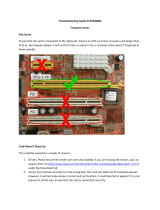
Open Enclosure (STEP 1)
Loosen the thumbscrews that retain the top cover of the chassis and slide the lid towards you as shown
from the pictures below:

ExpressBox 3400
Install Expansion Interface card
By default the Expansion Inte
need to install the Expansion Interface card.
If you need to replace the Expansion
Interface card or install a new
steps below:
1.
Turn off the Expansion chassis first.
2.
Unscrew the Expansion Interface
card.
3.
Install the
new Expansion Interface card
4.
Plug-in the Expansion Interface
card in
card. Installing the Interface card in
NOTE
Host Interface card (HIF), is the same exact card as th
SW4 switch on the
Expansion Interface card
NOT function if SW4 is set
to OFF=HOST. See picture below
Make sure to check that
the dip switch (SW4) is set to proper configuration. The toggle switch should be
to “ON=EXP” position, see picture
below.
ExpressBox 3400
|
Chapter 2 Hardware Installation
Interface card
(STEP 2)
By default the Expansion Inte
rface ca
rd is already installed.
need to install the Expansion Interface card.
Interface card or install a new
Expansion
Interface card follow these
Turn off the Expansion chassis first.
Disconnect the power cord.
card.
new Expansion Interface card
.
card in
to PCIe slot#0. This is the designated slot for the I
nterface
card. Installing the Interface card in
to a non-designated slot can cause the system to
malfunction.
Host Interface card (HIF), is the same exact card as th
e Expansion Interface card (
Expansion Interface card
is set to “ON=EXP.” The expansion
system will
to OFF=HOST. See picture below
for SW4
dip switch setting.
the dip switch (SW4) is set to proper configuration. The toggle switch should be
below.
Magma
Chapter 2 Hardware Installation
14
rd is already installed.
No
Interface card follow these
nterface
malfunction.
e Expansion Interface card (
EIF). The
system will
dip switch setting.
the dip switch (SW4) is set to proper configuration. The toggle switch should be
set

ExpressBox 3400
Install Host Interface card
(STEP 3)
Begin the installation of your
computer.
The
Host Interface card
a “full-
height” bracket.
For low profile case applications, you may need to change t
bracket to the low profile bracket that shipped with your system
below.
This is done by removing the screws that hold the card to the
bracket.
Be sure
action.
WARNING
You must only install the Host Interface card
Only use Interface card WITH bracket.
inserted into a PCIe slot.
Although
conventional PCI slots, you run the risk of damaging the PCI Express host card if you insert it
into a PCI slot.
1.
Once the host computer is
turned OFF
remove the cover.
2.
Check the red DIP switch (SW4
) on the
ExpressBox 3400
|
Chapter 2 Hardware Installation
(STEP 3)
Begin the installation of your
Host Interface
card by first powering down your
Host Interface card
is a “half-height,” x8-
capable PCIe card mou
height” bracket.
For low profile case applications, you may need to change t
he mounting
bracket to the low profile bracket that shipped with your system
, see
This is done by removing the screws that hold the card to the
Be sure
you are using proper ESD procedures when completing this
You must only install the Host Interface card
into a
PCI EXPRESS SLOT
.
Only use Interface card WITH bracket.
This will ensure that your PCIe host card can only be
Although
a Host Interface card
without brackets may fit into
conventional PCI slots, you run the risk of damaging the PCI Express host card if you insert it
turned OFF
and all power cords are disconnected from the AC outlet,
) on the
Interface card, make sure it is set to “OFF= HOST
”
Magma
Chapter 2 Hardware Installation
15
card by first powering down your
capable PCIe card mou
nted to
he mounting
, see
picture
This is done by removing the screws that hold the card to the
you are using proper ESD procedures when completing this
This will ensure that your PCIe host card can only be
without brackets may fit into
conventional PCI slots, you run the risk of damaging the PCI Express host card if you insert it
and all power cords are disconnected from the AC outlet,
”
.

Magma
ExpressBox 3400 | Chapter 2 Hardware Installation
16
3. Insert the Host Interface card into a vacant x8 (or x16) PCIe slot by gently pushing the card until it is
firmly seated. Then secure the card into the slot with a mounting screw.
It is important to know how many lanes the host computer slot can support. The Host Interface card does
not need to be configured for the same number of lanes as the host computer slot. The Host Interface
Card will train down to whatever the PCIe slot speed is that it detects.
For example, if the Host Interface Card is installed in a X4 lane card slot; leave the Host Interface Card
setting as is. The host computer dictates what link width and speed the expansion system will operate in.
Install PCIe Cards (STEP 4)
Remove slot covers and install PCIe cards.
Make sure that all cards are fully seated in their PCIe card slots. When correctly seated, there will be a firm
resistance when you pull up gently on the card. To keep the cards in place, secure them in the enclosure
with their retaining screws. After securing the cards verify that they do not touch each other.
Some card manufacturers recommend that you install their software driver prior to installing the card. If this
is the case, be sure to install the card driver before connecting EXPRESSBOX 3400 to the computer.

ExpressBox 3400
•
Slot 7
accepts all types of PCIe cards x1, x2, x4, x8 or x16
•
Slot 6
accepts all types of PCIe cards x1, x2, x4, x8 or x16
•
Slot 5
accepts all types of PCIe cards x1, x2, x4, x8
•
Slot 4
accepts all types of PCIe cards x1, x2, x4, x8 or x16
•
Slot 3
accepts all types of PCIe cards x1, x2, x4, x8 or x16
•
Slot 2 accepts all types of PCIe cards x1, x2, x4, x8 or x16
•
Slot 1 accepts all types of PC
Ie cards x1, x2, x4, x8
Aux Power Connectors
Some PCIe cards require extra power.
The ExpressBox
connectors / adapters (see pictures below). There are three
be used for providin
g extra power to cards.
High Power PCIe card installation
ExpressBox 3400
|
Chapter 2 Hardware Installation
accepts all types of PCIe cards x1, x2, x4, x8 or x16
.
accepts all types of PCIe cards x1, x2, x4, x8 or x16
.
accepts all types of PCIe cards x1, x2, x4, x8
or x16.
accepts all types of PCIe cards x1, x2, x4, x8 or x16
.
accepts all types of PCIe cards x1, x2, x4, x8 or x16
.
Slot 2 accepts all types of PCIe cards x1, x2, x4, x8 or x16
.
Ie cards x1, x2, x4, x8
or x16.
The ExpressBox
3400
power supply provides the following power
connectors / adapters (see pictures below). There are three
4-
pin Molex AUX power connectors that can
g extra power to cards.
And two (6+2 pin) PCIe connectors for GPUs.
Magma
Chapter 2 Hardware Installation
17
power supply provides the following power
pin Molex AUX power connectors that can

Magma
ExpressBox 3400 | Chapter 2 Hardware Installation
18
High Power PCIe cards, also known as High End PCIe cards, such as GPUs and other similar type of card
requires additional power (or AUX Power) to operate. High power PCIe cards or GPUs that requires auxiliary
power should come with power adapter cables.
There are three 4-pin Molex AUX power connectors and two (6+2 pin) PCIe connectors from the power
supply that can be used to provide power to your GPUs or High Power PCIe cards.
Other High Power PCIe cards may use different Aux power adapter connectors. Use the correct power
adapter for your PCIe cards.

ExpressBox 3400
Connect PCIe Cable (STEP 5)
Connect one end of the PCIe cable to
the back of
port of the Expansion Interface card
, see pictures below.
Connect the other end of the
PCIe cable to host computer (x8 port), see pictures below.
Electrostatic Discharge (ESD) Warning
The PCIe cables
are sensitive to electrostatic discharge (ESD).
precautions and packaging when handling the cables or when performing
installation and/or maintenance
To Disconnect Cable
ExpressBox 3400
|
Chapter 2 Hardware Installation
the back of
the Magma expansion unit, make sure to use the x8
, see pictures below.
PCIe cable to host computer (x8 port), see pictures below.
Electrostatic Discharge (ESD) Warning
The PCIe cables
are high performance communication cables and as such
are sensitive to electrostatic discharge (ESD).
Use appropriate anti
precautions and packaging when handling the cables or when performing
installation and/or maintenance
1.
Pull the orange tab while slowly pulling out the
cable from
the interface card.
2.
Failure to pull the orange tab while disconne
cting the
can break the connector inside the
Interface card.
Magma
Chapter 2 Hardware Installation
19
the Magma expansion unit, make sure to use the x8
are high performance communication cables and as such
Use appropriate anti
-static
precautions and packaging when handling the cables or when performing
cable from
cting the
cable
Interface card.

ExpressBox 3400
Cable Configuration
Attach Power Cord (STEP 6)
NOTE
If at all possible, plug
the power cord
computer into a shared power strip, preferably one that has surge and noise
suppression circuitry built into it.
1.
Make sure
the Power Switch is turned OFF
3400.
2.
Turn pow
er supply switch to ON position.
ExpressBox 3400
|
Chapter 2 Hardware Installation
You can only connect the PCIe
cable to
of the Interface card.
Note: D
o not plug in the PCIe cable to x16 port, the
expansion unit will not operate.
the power cord
from the expansi
on chassis and your host
computer into a shared power strip, preferably one that has surge and noise
suppression circuitry built into it.
the Power Switch is turned OFF
first before connecting the power cord to
ExpressBox
er supply switch to ON position.
Magma
Chapter 2 Hardware Installation
20
cable to
the x8 port
o not plug in the PCIe cable to x16 port, the
on chassis and your host
ExpressBox
/